Marine fuel gauge wiring diagram information
Home » Trend » Marine fuel gauge wiring diagram information
Your Marine fuel gauge wiring diagram images are available. Marine fuel gauge wiring diagram are a topic that is being searched for and liked by netizens now. You can Get the Marine fuel gauge wiring diagram files here. Download all free photos.
If you’re searching for marine fuel gauge wiring diagram pictures information linked to the marine fuel gauge wiring diagram keyword, you have visit the right blog. Our site always provides you with suggestions for refferencing the maximum quality video and picture content, please kindly surf and find more informative video articles and images that fit your interests.
Marine Fuel Gauge Wiring Diagram. Run wires from the adjustable fuel gauge. Wiring diagram for yamaha fuel gauge. Yamaha outboard digital multifunction gauge wiring diagram. Wiring diagram will come with several easy to follow wiring.
 Marine Fuel Gauge Wiring Diagram / Diagram Ezgo Fuel Gauge From karmilamucic.blogspot.com
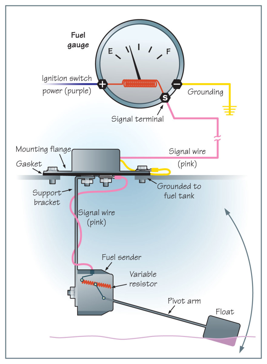
If your tank has an electric sender, it probably has a ground wire going back to the same place, or is attached to the tank ground lug and thus completes the ground side of the circuit. That black wire is the grounding wire from the metal deck fitting to (usually) a little welded tab on the fuel tank. Key on engine instrument made easy boats com 1963 1967 corvette schematic will inc corvetteforum chevrolet discussion marine level sender kus usa cell honda tech gas tank wires. Read the fuel level tank sender instructions and install the sender. Boat fuel gauge wiring diagram. Connect a wire to the gauge stud marked “ s” (signal) and secure with nut and lock washer.
800 x 600 px source.
A white wire and a black wire from the gauge are connected to a pink (usually) wire and a black wire respectively at the fuel quantity sender. Yamaha outboard digital multifunction gauge wiring diagram. Variety of marine fuel gauge wiring diagram. Most vendors will use one tachometer head to cover a variety of engines. Here is a diagram of what we have. 1 here shows the back of a typical gauge.
 Source: wholefoodsonabudget.com
Wiring a fuel gauge is much the same as wiring any other gauge on your boat. Run wires from the adjustable fuel gauge. 1 here shows the back of a typical gauge. The gauge with the backclamp supplied. The.frequently asked questions | moeller marinetesting a marine fuel sending unit.

Make sure this switch is set to. (see diagram on the next page for connections) standard case 3. A white wire and a black wire from the gauge are connected to a pink (usually) wire and a black wire respectively at the fuel quantity sender. At the top left of the diagram, we see the cylinder selector switch. Wiring diagram line we are make source the schematics, wiring diagrams and technical photos.
 Source: worldvisionsummerfest.com
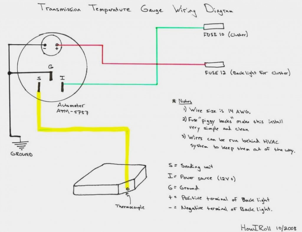
“s” for the sender, “g” or “—” for the ground, and “i” for the ignition. At the top left of the diagram, we see the cylinder selector switch. Viewline 52mm wiring diagram (2014) viewline standard resistive gauges 52mm installation sheet (2014) viewline temperature gauges 12/24 volt (2011) viewline temperature gauges 52mm (2008) To test senders the resistance values are shown at minimum and full gauge scales. Connect a wire to the gauge stud marked “ s” (signal) and secure with nut and lock washer.
Source: joodi123.blogspot.com
Key on engine instrument made easy boats com 1963 1967 corvette schematic will inc corvetteforum chevrolet discussion marine level sender kus usa cell honda tech gas tank wires. The gauge with the backclamp supplied. This adjustable fuel gauge must be calibrated part of the tank, as shown in diagram d. We can switch between senders, but even with the tanks 1/4 full we always get a full reading on the gauge for both tanks and an empty reading in the neutral position. After wiring gauge/sender, calibrate them (diagram e).
 Source: wiringschemas.blogspot.com
The.frequently asked questions | moeller marinetesting a marine fuel sending unit. Install the new gauge reconnect the wiring and turn on the power. Make sure this switch is set to. A white wire and a black wire from the gauge are connected to a pink (usually) wire and a black wire respectively at the fuel quantity sender. Connect a wire to the gauge stud marked “s” (signal) and secure with nut and lock washer.
 Source: karmilamucic.blogspot.com
It shows the components of the circuit as simplified shapes, and the power and signal links surrounded by the devices. “s” for the sender, “g” or “—” for the ground, and “i” for the ignition. Install the new gauge reconnect the wiring and turn on the power. Boat fuel gauge wiring diagram. Connect a wire to the gauge stud marked “ s” (signal) and secure with nut and lock washer.
 Source: worldvisionsummerfest.com
You are able to usually rely on wiring diagram being an crucial reference that may assist you to save money and time. How to install a moeller fuel gauge. Onnect the other end of the wire to the connection post on the back of the gauge marked “s”. (see diagram on the next page for connections) standard case 3. The fuel gauge should now show the correct fuel level in.
 Source: afiqahstory88.blogspot.com
If your tank has an electric sender, it probably has a ground wire going back to the same place, or is attached to the tank ground lug and thus completes the ground side of the circuit. These instructions concern only fuel gauge installations. Viewline 52mm wiring diagram (2014) viewline standard resistive gauges 52mm installation sheet (2014) viewline temperature gauges 12/24 volt (2011) viewline temperature gauges 52mm (2008) 1 here shows the back of a typical gauge. For the fuel gauge its best to remove it from the tank and manually work the float mechanism to see if the gauge then moves.
 Source: wholefoodsonabudget.com
“s” for the sender, “g” or “—” for the ground, and “i” for the ignition. Wiring diagram for yamaha fuel gauge. Wiring diagram boat fuel gauge wiring diagram line wiring diagram. For technical assistance, contact faria® marine instruments customer service between am and. Which some will say should be called a rheostat.
 Source: easywiring.info
Read the fuel level tank sender instructions and install the sender. If your tank has an electric sender, it probably has a ground wire going back to the same place, or is attached to the tank ground lug and thus completes the ground side of the circuit. Read the fuel level tank sender instructions and install the sender. Pull the wire from the fuel sender up through your boat�s dash. Install the new gauge, reconnect the wiring and turn on the power.
 Source: wholefoodsonabudget.com
At the top left of the diagram, we see the cylinder selector switch. After wiring gauge/sender, calibrate them (diagram e). (see diagram on the next page for connections) standard case 3. Wiring a fuel gauge is much the same as wiring any other gauge on your boat. Veratron flex gauge 52mm nmea2000 12/24v.
 Source: karmilamucic.blogspot.com
Install the new gauge reconnect the wiring and turn on the power. Wiring a fuel gauge is much the same as wiring any other gauge on your boat: Fuel systems (marine) connect two test meter wires to two sender terminals (or center terminal & flange if. Connect a wire to the gauge stud marked “s” (signal) and secure with nut and lock washer. The gauge with the backclamp supplied.
Source: bodole.blogspot.com
Connect the wire to the sender. 800 x 600 px source. Boat fuel gauge wiring diagram. Connect a wire to the gauge stud marked “ s” (signal) and secure with nut and lock washer. Beginning with the tachometer, fig.
 Source: strategiccontentmarketing.co
Install the new gauge reconnect the wiring and turn on the power. For technical assistance, contact faria® marine instruments customer service between am and. (see diagram on the next page for connections) standard case 3. Wiring diagram for boat fuel sending unit wiring diagram line wiring diagram. If your tank has an electric sender, it probably has a ground wire going back to the same place, or is attached to the tank ground lug and thus completes the ground side of the circuit.
 Source: rajuyolo07.blogspot.com
How to install a moeller fuel gauge. Connect opposite end to the fuel level sender’s signal wire or terminal. Wiring diagram line we are make source the schematics, wiring diagrams and technical photos. At the top left of the diagram, we see the cylinder selector switch. Includes hardware and adapters for basic installation on gm cars.
 Source: easywiring.info
Special caution should be taken when working on or near tanks that have, or have had, fuel in them. To test senders the resistance values are shown at minimum and full gauge scales. The fuel gauge should now show the correct fuel level in the tank. Onnect the other end of the wire to the connection post on the back of the gauge marked “s”. Yamaha outboard digital multifunction gauge wiring diagram.
Source: thehulltruth.com
How to test and replace your fuel gauge sending unit sail magazine sender wiring question the hull truth boating fishing forum troubleshoot boat s mag dual units one marine level kus usa wire up a corvetteforum chevrolet corvette discussion again ribnet forums. 800 x 600 px source. It is recommended that insulated wire terminals, preferably ring type, be used on all We weeded out alot of useless crap and came up with this. Make sure this switch is set to.
 Source: afiqahstory88.blogspot.com
Connect a wire to the gauge stud marked “ s” (signal) and secure with nut and lock washer. Includes hardware and adapters for basic installation on gm cars. Fuel systems marine voltage i to g terminal 10 to 16 volts. Wiring diagram boat fuel gauge wiring diagram line wiring diagram. Slip the female blade connector on the wire from the fuel sender onto the s.
This site is an open community for users to submit their favorite wallpapers on the internet, all images or pictures in this website are for personal wallpaper use only, it is stricly prohibited to use this wallpaper for commercial purposes, if you are the author and find this image is shared without your permission, please kindly raise a DMCA report to Us.
If you find this site good, please support us by sharing this posts to your favorite social media accounts like Facebook, Instagram and so on or you can also save this blog page with the title marine fuel gauge wiring diagram by using Ctrl + D for devices a laptop with a Windows operating system or Command + D for laptops with an Apple operating system. If you use a smartphone, you can also use the drawer menu of the browser you are using. Whether it’s a Windows, Mac, iOS or Android operating system, you will still be able to bookmark this website.
Category
Related By Category
- Predator 670 engine wiring diagram Idea
- Frsky x8r wiring diagram information
- Pioneer ts wx130da wiring diagram Idea
- Johnson 50 hp wiring diagram Idea
- Kohler voltage regulator wiring diagram Idea
- Johnson 50 hp outboard wiring diagram information
- Kti hydraulic remote wiring diagram Idea
- Pyle plpw12d wiring diagram information
- Tx9600ts wiring diagram information
- Lifan 50cc wiring diagram information