Lutron ecosystem ballast wiring diagram information
Home » Trending » Lutron ecosystem ballast wiring diagram information
Your Lutron ecosystem ballast wiring diagram images are ready. Lutron ecosystem ballast wiring diagram are a topic that is being searched for and liked by netizens now. You can Get the Lutron ecosystem ballast wiring diagram files here. Download all free photos and vectors.
If you’re looking for lutron ecosystem ballast wiring diagram images information related to the lutron ecosystem ballast wiring diagram keyword, you have pay a visit to the right blog. Our site always gives you hints for seeing the highest quality video and picture content, please kindly surf and find more enlightening video content and graphics that match your interests.
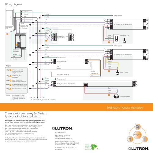
Lutron Ecosystem Ballast Wiring Diagram. All models listed here are ul and csa certified, unless otherwise noted. Consult the factory for other wiring diagrams. Dimmable electronic power supply wiring diagram. Search the lutron archive of wiring diagrams.

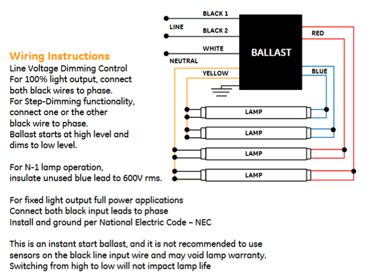
All wiring should match the wiring diagram on the ballast case. Lutron offers several different ways to install and control our dimming ballasts. Lutron dimming ballast wiring diagram. Lutron dimming ballast wiring diagram 3 lutron ecosystem dimming. Integral sensor connection provides power for and responds to one occupancy sensor, one photo sensor and one personal control input (ir or wall station) A wiring summary is shown below:
Lamp compatibility table type of lamps that can be used with this ballast ballast wiring diagram shows how the ballast is wired to the lamps fluorescent tube diameters.
Lutron ® ecosystem protocol 1.1 lutron ® ecosystem protocol specifications ecosystem technology is a control method for leds that provides addressing of individual fixtures and status feedback. See the wiring diagrams in the. You can also call us at +44 (0)207.702.0657. Product data sheets in pdf format: 1 +20v daylight occ ir common class 2 (#22 awg solid) e2 e1. Consult the factory for other wiring diagrams.
 Source: schematron.org
Ecosystem ® power wiring diagrams 1 ballast is grounded via the case or terminal. 2 wire colors shown are for lutron® controls and ballasts only. Verify that the voltage requirements of the desired ballast matches that of your region. Lutron offers several different ways to install and control our dimming ballasts. All models listed here are ul and csa certified, unless otherwise noted.
 Source: yumpu.com
Lutron�s ecosystem lighting network starts with one simple but essential building block— the ecosystem. Ecosystem ® power wiring diagrams 1 ballast is grounded via the case or terminal. Use this guide for ballast wiring details. You can also call us at +1.888.lutron1 (588.7661). A wiring diagram is a streamlined conventional pictorial depiction of an electric circuit.

View all technical documentation for this item. Each feature is designed around what is most important to you how well your building is working. A wiring diagram is a streamlined conventional pictorial depiction of an electric circuit. A wiring summary is shown below: Dimming control wires may not match ballast wire colors.
 Source: galvinconanstuart.blogspot.com
You can also call us at +1.888.lutron1 (588.7661). Lutron offers several different ways to install and control our dimming ballasts. All wiring should match the wiring diagram on. In a 3 way switch there is a master dimmer and a remote dimmer. Along with hot and neutral, the dimming signal is communicated via a third wire called dimmed hot.
 Source: wiringall.com
Lutron diva 3 way dimmer wiring diagram gallery. All wiring should match the wiring diagram on. 3 the constant hot must not be wired to a switching device. Digitally dimmable ballasts for fluorescent lamps, e.g. Lutron ® ecosystem protocol 1.1 lutron ® ecosystem protocol specifications ecosystem technology is a control method for leds that provides addressing of individual fixtures and status feedback.
 Source: wiringschemas.blogspot.com
Lutron dimming ballast wiring diagram. Lutron ecosystem ec5t832gunv3l dimming ballast; Lutron offers several different ways to install and control our dimming ballasts. This lutron dimming system allows for individual control of fixtures similar to dali, and utilizes a hot dimming wire and is. All models listed here are ul and csa certified, unless otherwise noted.
 Source: schematron.org
Please note that not all listed models can be used in all regions. It is therefore important that these two pins are not shorted together in the socket. Search the lutron archive of wiring diagrams. Installing and wiring an ecosystem dimming ballast. All wiring should match the wiring diagram on the ballast case.
 Source: wiring121.blogspot.com
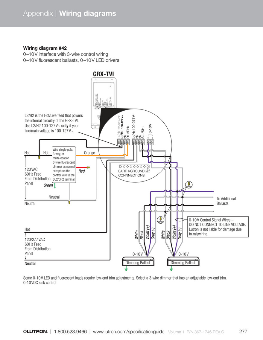
Advance mark vii v electronic dimming ballasts lutron® eco® 10 volt option wire controls according to the appropriate wiring diagram shown in. Search the lutron archive of wiring diagrams. Pca excel one4all, pca eco, pca basic. Each feature is designed around what is most important to you how well your building is working. A wiring diagram is a simplified traditional photographic representation of an electric circuit.
 Source: wiring01.blogspot.com
Source: wiring01.blogspot.com
Lamp compatibility table type of lamps that can be used with this ballast ballast wiring diagram shows how the ballast is wired to the lamps fluorescent tube diameters. Cfl ballast 9w working of fuse tube light by 4 diode schematic diagram of energy saving lamps diac advantage 9 watt cfl circuit diagram electronic. Diagrams for specific situations can be located within this pdf file by using the following methods. This makes it easy to digitally assign one or many fixtures without complicated wiring. Along with hot and neutral, the dimming signal is communicated via a third wire called dimmed hot.
 Source: wiringschemas.blogspot.com
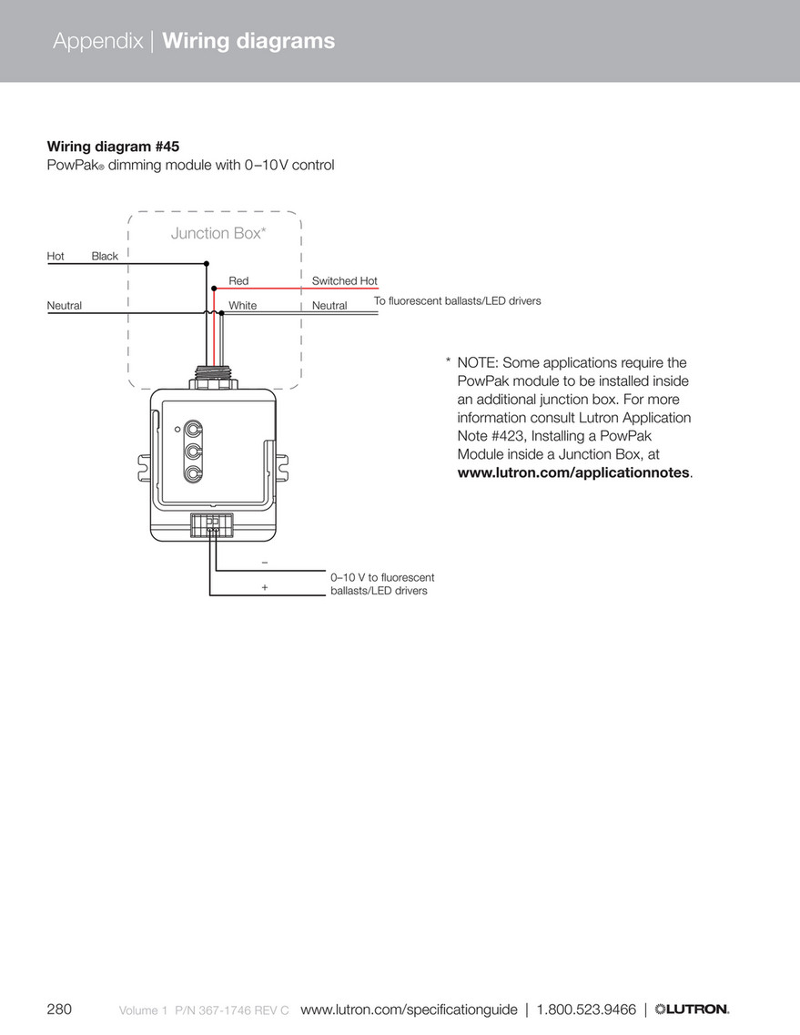
Use this guide for ballast wiring details. 2 wire colors shown are for lutron® controls and ballasts only. A wiring diagram is a simplified conventional pictorial representation of an electrical circuit. Consult the factory for other wiring diagrams. Lutron ecosystem ec5t832gunv3l dimming ballast;
 Source: skippingtheinbetween.blogspot.com
Lutron dimming ballast wiring diagram 3 lutron ecosystem dimming. Lutron�s ecosystem lighting network starts with one simple but essential building block— the ecosystem. Lutron dimming ballast wiring diagram 3 lutron ecosystem dimming. A wiring diagram is a streamlined conventional pictorial depiction of an electric circuit. Dimming control wires may not match ballast wire colors.
 Source: schematron.org
Lutron�s ecosystem lighting network starts with one simple but essential building block— the ecosystem. 277v ballast wiring lutron ecosystem ballast wiring diagram free download, t8 led bulb replacement wiring instructions specs from, emergency ballast wiring guide lightalarms, how to wire a replacement ballast with different wiring, eesb electronic fluorescent sign ballasts frontier lighting, hatch hr1300 277 legacy 13w cfl ballast 277v side leads Lutron offers several different ways to install and control our dimming ballasts. 3 the constant hot must not be wired to a switching device. With such an illustrative manual, you will have the ability to troubleshoot, avoid, and full your tasks without difficulty.
 Source: wiringforums.com
Cfl ballast 9w working of fuse tube light by 4 diode schematic diagram of energy saving lamps diac advantage 9 watt cfl circuit diagram electronic. 3 the constant hot must not be wired to a switching device. Lutron offers several different ways to install and control our dimming ballasts. Emergency lighting ballast wiring diagram. Lutron diva 3 way dimmer wiring diagram gallery.
 Source: ballastshop.com
1 +20v daylight occ ir common class 2 (#22 awg solid) e2 e1. 3 the constant hot must not be wired to a switching device. Digitally dimmable ballasts for fluorescent lamps, e.g. Please note that not all listed models can be used in all regions. Advance mark vii v electronic dimming ballasts lutron® eco® 10 volt option wire controls according to the appropriate wiring diagram shown in.

You can also call us at +44 (0)207.702.0657. A wiring summary is shown below: Lutron�s ecosystem lighting network starts with one simple but essential building block— the ecosystem. Ecosystem ® power wiring diagrams 1 ballast is grounded via the case or terminal. View all technical documentation for this item.
 Source: tops-stars.com
Each feature is designed around what is most important to you how well your building is working. Lutron�s ecosystem lighting network starts with one simple but essential building block— the ecosystem. Product data sheets in pdf format: This lutron dimming system allows for individual control of fixtures similar to dali, and utilizes a hot dimming wire and is. Digitally dimmable ballasts for fluorescent lamps, e.g.

All models listed here are ul and csa certified, unless otherwise noted. Please note that not all listed models can be used in all regions. Emergency lighting ballast wiring diagram. Lutron dimming ballast wiring diagram. All wiring should match the wiring diagram on the ballast case.
 Source: schematron.org
A wiring diagram is a simplified traditional photographic representation of an electric circuit. A wiring summary is shown below: Advance mark vii v electronic dimming ballasts lutron® eco® 10 volt option wire controls according to the appropriate wiring diagram shown in. Each feature is designed around what is most important to you how well your building is working. Lutron ecosystem is based on the dali communication standard but uses a proprietary dimming protocol which ensures that lutron dimming drivers will pair well with lutron dimmers and control systems.
This site is an open community for users to do submittion their favorite wallpapers on the internet, all images or pictures in this website are for personal wallpaper use only, it is stricly prohibited to use this wallpaper for commercial purposes, if you are the author and find this image is shared without your permission, please kindly raise a DMCA report to Us.
If you find this site adventageous, please support us by sharing this posts to your own social media accounts like Facebook, Instagram and so on or you can also bookmark this blog page with the title lutron ecosystem ballast wiring diagram by using Ctrl + D for devices a laptop with a Windows operating system or Command + D for laptops with an Apple operating system. If you use a smartphone, you can also use the drawer menu of the browser you are using. Whether it’s a Windows, Mac, iOS or Android operating system, you will still be able to bookmark this website.
Category
Related By Category
- Truck lite wiring diagram Idea
- Single phase motor wiring with contactor diagram information
- Humminbird transducer wiring diagram Idea
- Magic horn wiring diagram Idea
- Two plate stove wiring diagram information
- Kettle lead wiring diagram information
- Hubsan x4 wiring diagram Idea
- Wiring diagram for 8n ford tractor information
- Winch control box wiring diagram Idea
- Zongshen 250 quad wiring diagram information