Low voltage motor wiring diagram Idea
Home » Trending » Low voltage motor wiring diagram Idea
Your Low voltage motor wiring diagram images are ready in this website. Low voltage motor wiring diagram are a topic that is being searched for and liked by netizens now. You can Download the Low voltage motor wiring diagram files here. Get all royalty-free photos.
If you’re looking for low voltage motor wiring diagram pictures information related to the low voltage motor wiring diagram topic, you have pay a visit to the ideal blog. Our website always gives you hints for downloading the maximum quality video and image content, please kindly surf and locate more enlightening video articles and graphics that fit your interests.
Low Voltage Motor Wiring Diagram. Wiring a motor for 230 volts is the same as wiring for 220 or 240 volts. Residential power is usually in the form of 110 to 120 volts or 220 to 240 volts. In such case, each cable will. Of a low voltage wire comes in contact with 120v the higher voltage can damage what ever is at the end of the low voltage wire.
 3 Phase Low Voltage Motor Wiring Wiring Diagram From facybulka.me
Be sure to identify the proper wiring diagram for the motor you are installing. In both cases, the supply voltage is connected to u1 (t1), v1 (t2) and w1 (t3). There are also other components like ground, switch, motor, and inductor. 12 volt 20 watt light bulb circuit. Determining the location of the wiring problem can. Low voltage motor wiring diagram.
Since the motor is a 230460 and you have a 208v supply you would wire it low voltage.
There are also other components like ground, switch, motor, and inductor. That s it for low voltage wiring. Each lead may have one or more cables comprising that lead. If you have difficulty determining the proper wiring diagram for your motor, please contact techtop for assistance. Low voltage 3 phase wiring diagram wiring diagram document guide. If this motor is installed as part of a motor control drive
 Source: practicalmachinist.com
I am probably going to use it wired for low voltage. 4&7, 5&8, 6&9, 10&11&12 : You would wire it high voltage if you were supplying 460v. 3 phase low voltage motor wiring diagram i asked what the voltage was a high limit control a low water cutoff as a safety device and a thermostat setting the comfort level. Three phase induction motor blow up diagram of construction parts nursing student tips motor works education information.
 Source: wholefoodsonabudget.com
That being said, there is a wide range of different motors and what you have on hand can be completely different. Three phase induction motor blow up diagram of construction parts nursing student tips motor works education information. Make sure that the voltage you will be. From high to low voltage. How to wire an electric motor to run on both 110 and 220 low voltage motor control centers.
 Source: 2020cadillac.com
That s it for low voltage wiring. Of a low voltage wire comes in contact with 120v the higher voltage can damage what ever is at the end of the low voltage wire. In such case, each cable will. Residential power is usually in the form of 110 to 120 volts or 220 to 240 volts. In the right diagram below a 20 w bulb with a 12v source draws 1 6 amps 10 times more current than a 120v source.
 Source: facybulka.me
Make sure that the voltage you will be. The first step is to figure out the voltage of your phases. Low voltage 3 phase wiring diagram wiring diagram document guide. Since the motor is a 230/460, and you have a 208v supply, you would wire it low voltage. That being said, there is a wide range of different motors and what you have on hand can be completely different.
 Source: facybulka.me
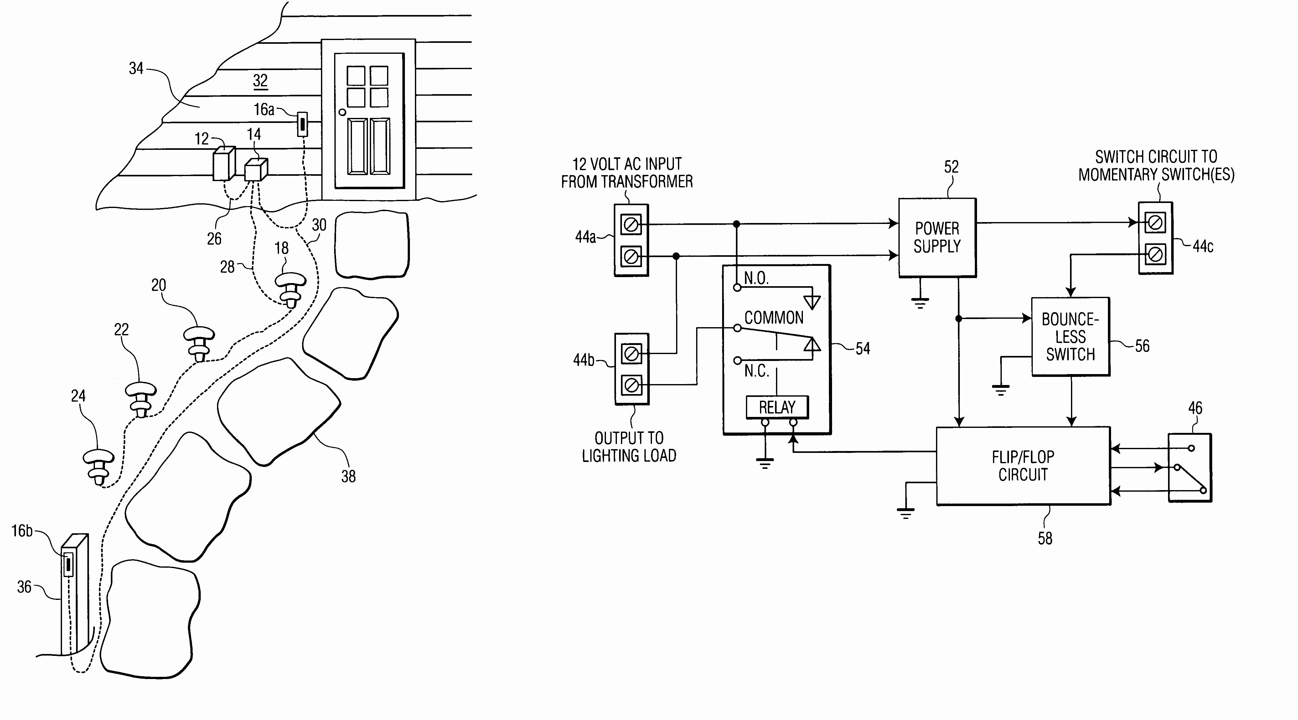
How to install low voltage lighting. 8100 0300 01 low voltage outdoor 300 watt digital transformer. In the left diagram below a 20 watt w bulb with a 120v source draws 16 amp. 120 volt electric motor wiring diagram single phase. The higher voltage in these applications is usually 440 or 480 volts while the low voltage is usually 208 or 220 volts.
 Source: facybulka.me
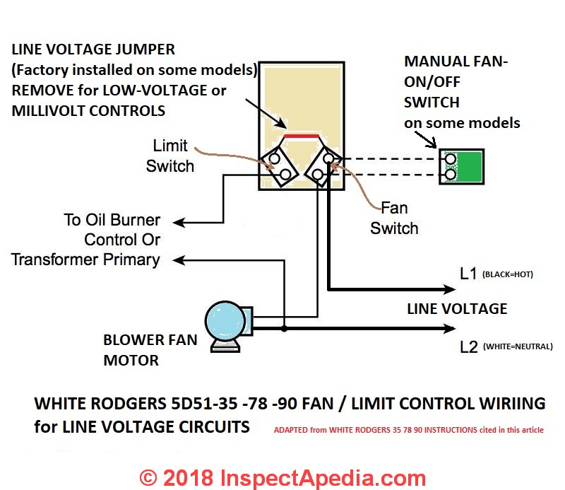
3 phase low voltage motor wiring diagram i asked what the voltage was a high limit control a low water cutoff as a safety device and a thermostat setting the comfort level. Changing from low to high voltage is carried out in reverse order. 12 volt 20 watt light bulb circuit. Occasionally, the cables will cross. Wiring your motor connect the motor as shown in the connection diagram on the motor nameplate.
 Source: wiringall.com
Residential power is usually in the form of 110 to 120 volts or 220 to 240 volts. 1 motor ohm values chart. 120 volt electric motor wiring diagram single phase. Since the motor is a 230460 and you have a 208v supply you would wire it low voltage. Each lead may have one or more cables comprising that lead.
 Source: facybulka.me
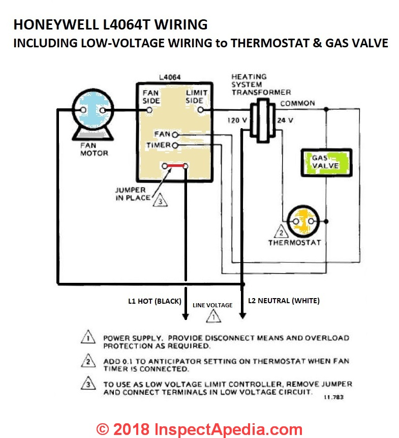
How to wire an electric motor to run on both 110 and 220 low voltage motor control centers. The first step is to figure out the voltage of your phases. Internal wiring diagrams of small and fractional horsepower electric motors. Low voltage motor wiring diagram. And whether a 9 lead motor is wired wye or delta at the factory has no effect on whether your supply is wye delta.
Source: electricmotorsindia.bccaltabrianza.it
Diagram dd6 diagram dd7 m 1 ln e diagram dd8 ln e l1 l2 l3 s c z1 u2 z2 u1 cap. 4&7, 5&8, 6&9, 10&11&12 : A wiring diagram is a simplified standard pictorial depiction of an electric circuit. 1 motor ohm values chart. In such case, each cable will.
Source: justanswer.com
Residential power is usually in the form of 110 to 120 volts or 220 to 240 volts. In the right diagram below a 20 w bulb with a 12v source draws 1 6 amps 10 times more current than a 120v source. That s it for low voltage wiring. By facybulka posted on june 25, 2019 21 views. When you make use of your finger or perhaps the actual circuit with your eyes, it is easy to mistrace the circuit.
 Source: wiringall.com
A wiring diagram is a simplified standard pictorial depiction of an electric circuit. There are also other components like ground, switch, motor, and inductor. I am probably going to use it wired for low voltage. Low voltage ac induction motor 3 phase motors wound open type series. From high to low voltage.
 Source: facybulka.me
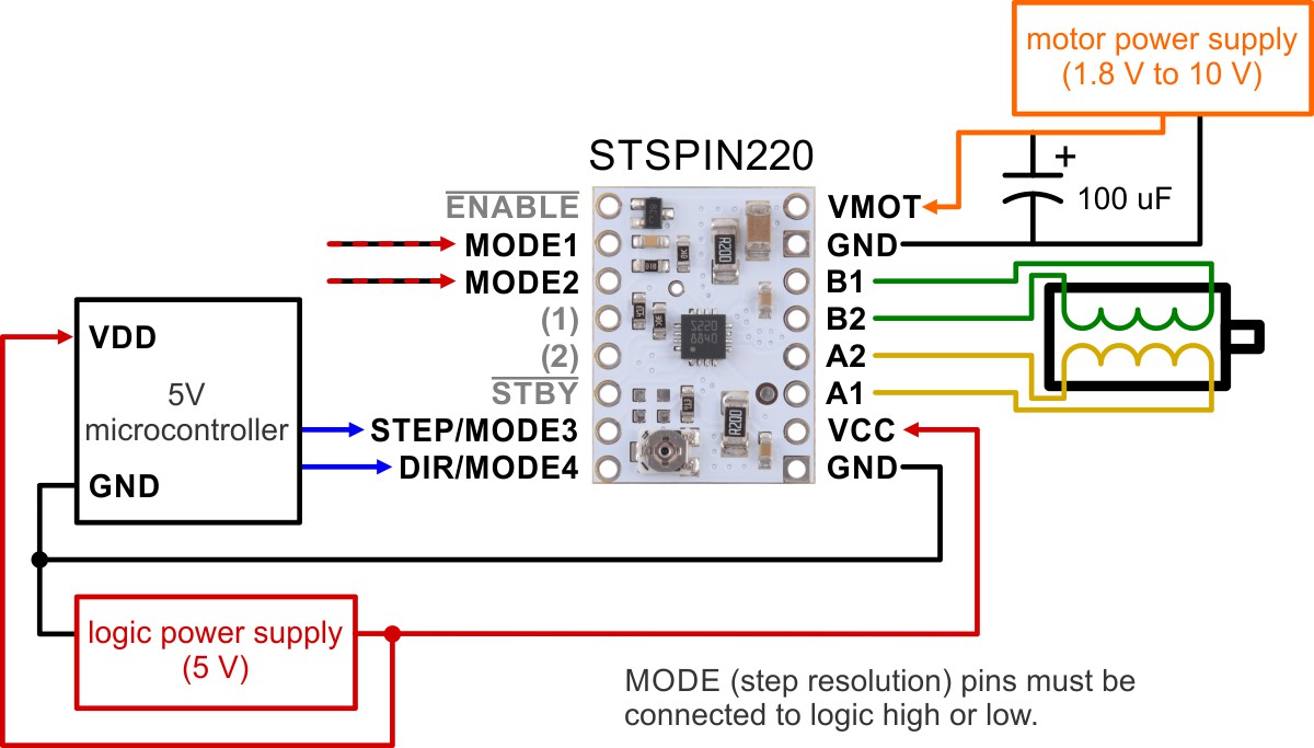
3 phase motor wiring diagram low voltage. The most common components are capacitor, resistor, and battery. The direction of ro tation is changed by exchanging two Changing from low to high voltage is carried out in reverse order. 1 motor ohm values chart.
 Source: faceitsalon.com
Determining the location of the wiring problem can. Split phase motor dual voltage reversible rotation capacitor motor single phase wiring diagrams always use wiring diagram supplied on motor nameplate. Wiring a motor for 230 volts is the same as wiring for 220 or 240 volts. The first step is to figure out the voltage of your phases. Motor wiring diagram 9 lead, dual voltage, wye connection part winding start (pws) on low voltage to reverse direction of rotation, interchange leads l1 & l2.
 Source: chadwellsupply.com
Diagram dd6 diagram dd7 m 1 ln e diagram dd8 ln e l1 l2 l3 s c z1 u2 z2 u1 cap. Split phase motor dual voltage reversible rotation capacitor motor single phase wiring diagrams always use wiring diagram supplied on motor nameplate. If you have difficulty determining the proper wiring diagram for your motor, please contact techtop for assistance. I am probably going to use it wired for low voltage. Malibu low voltage transformer wiring diagram related problems.
 Source: faceitsalon.com
Wiring a motor for 230 volts is the same as wiring for 220 or 240 volts. Ad find 3 phase motors. Occasionally, the cables will cross. If you have difficulty determining the proper wiring diagram for your motor, please contact techtop for assistance. 3 phase motor wiring diagram 9.
 Source: pinterest.ca
8100 0300 01 low voltage outdoor 300 watt digital transformer. By facybulka posted on june 25, 2019 21 views. 4&7, 5&8, 6&9, 10&11&12 : 1 trick that we 2 to printing a similar wiring plan off twice. In the right diagram below a 20 w bulb with a 12v source draws 1 6 amps 10 times more current than a 120v source.
 Source: ricardolevinsmorales.com
Mlrt low voltage watt power pack with timer. Ad find 3 phase motors. I have a single phase, 1hp, 60/50hz motor than i need to wire a pigtail on. 120 volt electric motor wiring diagram single phase. Damage will occur if the motor is operated with load for more than 30 seconds on the
 Source: facybulka.me
Everything depends on circuit that’s being assembled. 8100 0300 01 low voltage outdoor 300 watt digital transformer. Wiring diagram book a1 15 b1 b2 16 18 b3 a2 b1 b3 15 supply voltage 16 18 l m h 2 levels b2 l1 f u 1 460 v f u 2. 120 volt electric motor wiring diagram single phase. Mlrt low voltage watt power pack with timer.
This site is an open community for users to share their favorite wallpapers on the internet, all images or pictures in this website are for personal wallpaper use only, it is stricly prohibited to use this wallpaper for commercial purposes, if you are the author and find this image is shared without your permission, please kindly raise a DMCA report to Us.
If you find this site value, please support us by sharing this posts to your preference social media accounts like Facebook, Instagram and so on or you can also bookmark this blog page with the title low voltage motor wiring diagram by using Ctrl + D for devices a laptop with a Windows operating system or Command + D for laptops with an Apple operating system. If you use a smartphone, you can also use the drawer menu of the browser you are using. Whether it’s a Windows, Mac, iOS or Android operating system, you will still be able to bookmark this website.
Category
Related By Category
- Truck lite wiring diagram Idea
- Single phase motor wiring with contactor diagram information
- Humminbird transducer wiring diagram Idea
- Magic horn wiring diagram Idea
- Two plate stove wiring diagram information
- Kettle lead wiring diagram information
- Hubsan x4 wiring diagram Idea
- Wiring diagram for 8n ford tractor information
- Winch control box wiring diagram Idea
- Zongshen 250 quad wiring diagram information