Loop wiring diagram instrumentation Idea
Home » Trending » Loop wiring diagram instrumentation Idea
Your Loop wiring diagram instrumentation images are ready in this website. Loop wiring diagram instrumentation are a topic that is being searched for and liked by netizens today. You can Download the Loop wiring diagram instrumentation files here. Find and Download all free vectors.
If you’re looking for loop wiring diagram instrumentation images information connected with to the loop wiring diagram instrumentation interest, you have come to the right blog. Our website always provides you with suggestions for refferencing the highest quality video and image content, please kindly surf and find more enlightening video content and graphics that match your interests.
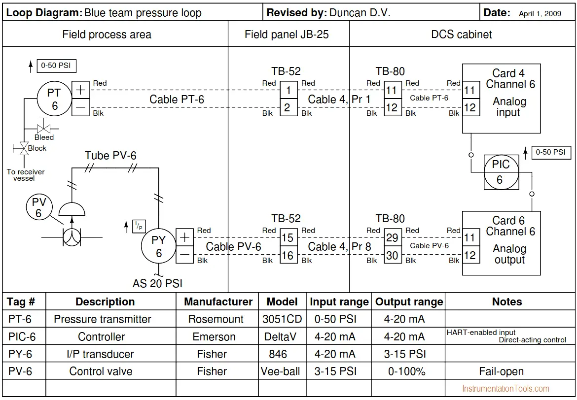
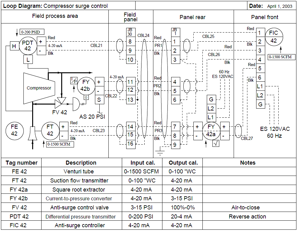
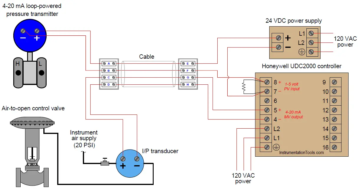
Loop Wiring Diagram Instrumentation. Instrument loop diagrams are also called instrument loop drawings or loop sheets. The loop configuration is as follows: When a loop diagram shows you exactly what wire color to expect at exactly what point in an instrumentation system, and exactly what terminal that wire should connect to, it becomes much easier to proceed with any troubleshooting, calibration, or upgrade task. Loop checking is the process that confirms the components wired correctly and also helps to ensure that the system is functioning as designed.
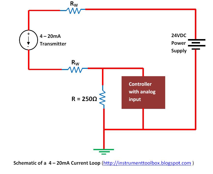 Basics of The 4 20mA Current Loop Learning From instrumentationtoolbox.com
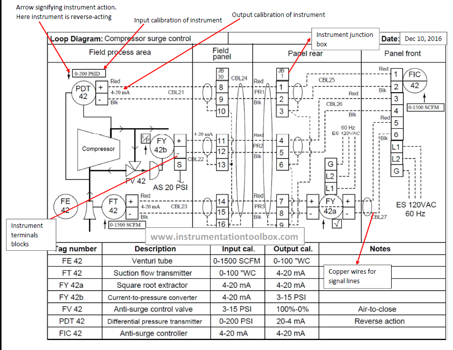
Loop wiring diagram instrumentation pdf. Rw = the loop wire’s resistance in ohms. The hot and neutral terminals on each fixture are spliced with a pigtail to the circuit wires which then continue on to the next light. Loop diagram symbols and p&ids p&ids and loop diagrams p&ids and loop diagrams are construction and documentation drawings that depict the flow of the process and illustrate the instrumentation control and measurement. Electrical loop diagrams wiring diagram. Dashed lines in instrument drawings represent individual copper wires rather than whole cables terminal blocks where wires connect.
Piping and instrumentation diagram p id diagrama de.
Wilkerson instrument company inc blog wilkerson instrument. What is an instrumentation loop diagram field automation plc programming scada pid control system 15 questions tools instrument diagrams dcs engineers community sheets and doentation textbook excel com drawings nikolay bozov wiring drawing conversion for spi aveva plant design software manager according to standard isa ties 486 78 kb bibliocad ispatguru. Rw = the loop wire’s resistance in ohms. It contains all associated electrical and piping connections and should contain all of the information needed to accommodate the intended uses. The hot and neutral terminals on each fixture are spliced with a pigtail to the circuit wires which then continue on to the next light. An instrument loop diagram can be effective on any size project from one or two loops up to large and complex installations.
Source: field-instrument.blogspot.com
Each instrument bubble in a loop diagram represent an individual device with its own terminals for connecting wires. Process equipment and instrument symbols email: Loop diagrams are very important instrumentation design deliverable. The hot and neutral terminals on each fixture are spliced with a pigtail to the circuit wires which then continue on to the next light. The loop checking checks the connection between each.
Source: industrialinstrumentationsolutions.blogspot.com
Single wires run from the marshalling strip to the io cards of the plc to complete the loop. I = the current flowing through the loop wires in amperes; Loop diagrams are fairly constrained in their layout as per the isa 5.1 standard. Process equipment and instrument symbols email: It helps them to track each and every tag correctly and easily while keeping log of the activities.
 Source: engineers-excel.com
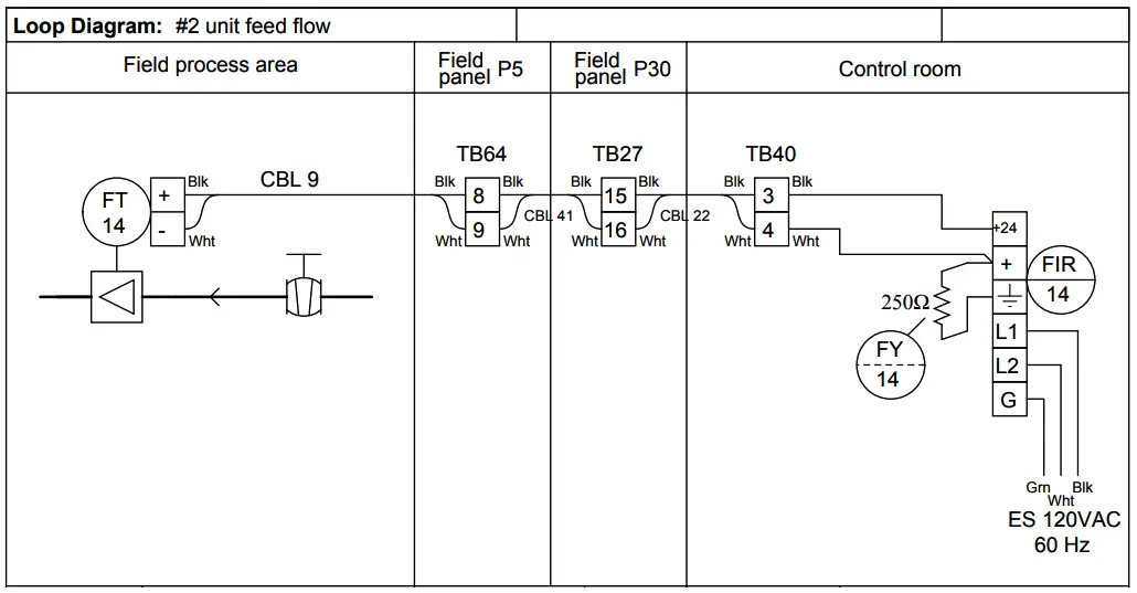
It contains all associated electrical and piping connections and should contain all of the information needed to accommodate the intended uses. Loop diagrams are imagined and understood by many people as a kind of extended wiring diagrams. Beside above, how do you do a loop check? It also shows the process operating conditions of major equipment. Each instrument bubble in a loop diagram represent an individual device with its own terminals for connecting wires.
 Source: instrumentationtoolbox.com
Rw = the loop wire’s resistance in ohms. Process equipment and instrument symbols email: What is an instrumentation loop diagram field instrumentation how to create instrument loop. A loop diagram will detail the connections of A plot plan shows the exact location of each equipment.
 Source: instrumentationtools.com
The hot and neutral terminals on each fixture are spliced with a pigtail to the circuit wires which then continue on to the next light. 15 loop diagram questions resources at switch lighting circuits electric diagrams sheets control light wiring do it electrical cad design software nikolay bozov automation and drawing looped ceiling rose what is an instrumentation ispatguru example feedback v relay to powered devices. Mainly for construction contractor who will install and wire all the loops. Each instrument bubble in a loop diagram represent an individual device with its own terminals for connecting wires. Each instrument bubble in a loop diagram represent an individual device with its own terminals for connecting wires.
 Source: instrumentationtools.com
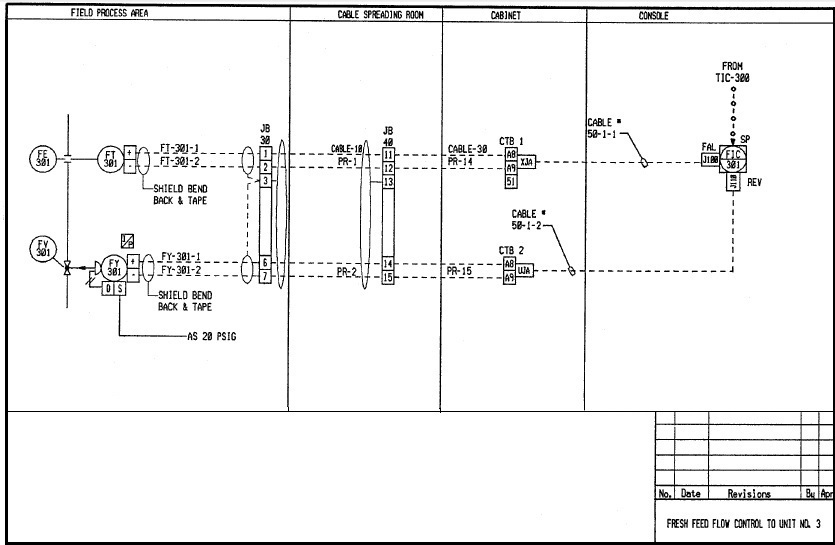
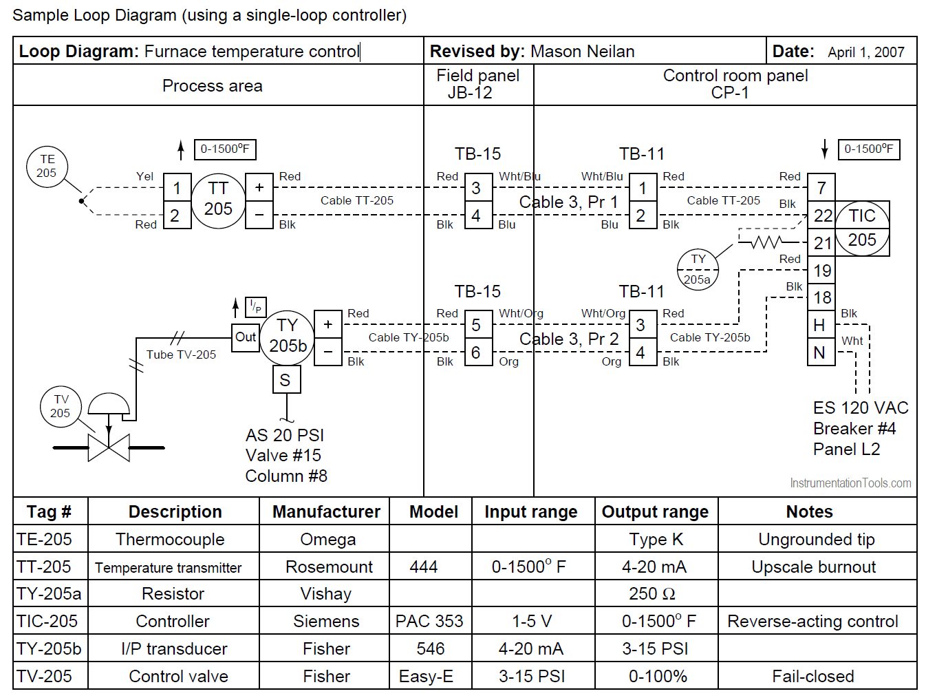
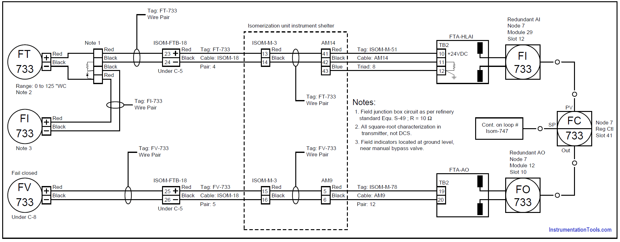
Dashed lines in instrument drawings represent individual copper wires rather than whole cables terminal blocks where wires connect. I = the current flowing through the loop wires in amperes; Instrumentation and control (i&c) personnel must demonstrate a familiarity level. These set of drawings are more detailed than process and instrument diagrams (p&ids). Each instrument bubble in a loop diagram represent an individual device with its own terminals for connecting wires.
 Source: instrumentationtools.com
Wilkerson instrument company inc blog wilkerson instrument. Rw = the loop wire’s resistance in ohms. Instrumentation diagrams are used for understanding the process system. A loop drawing shows the electrical wiring details of instruments. The process is illustrated in sections or subsystems of the process called loops.
 Source: instrumentationtools.com
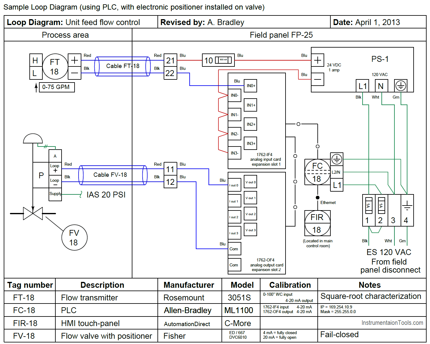
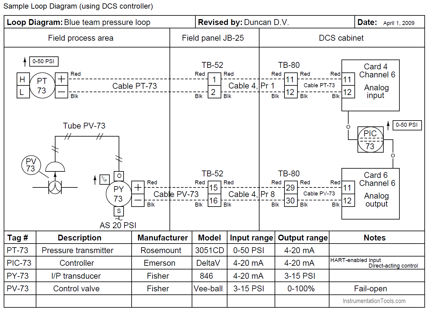
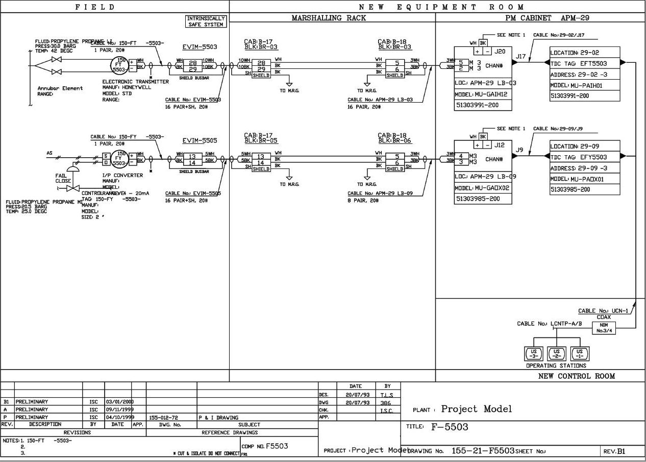
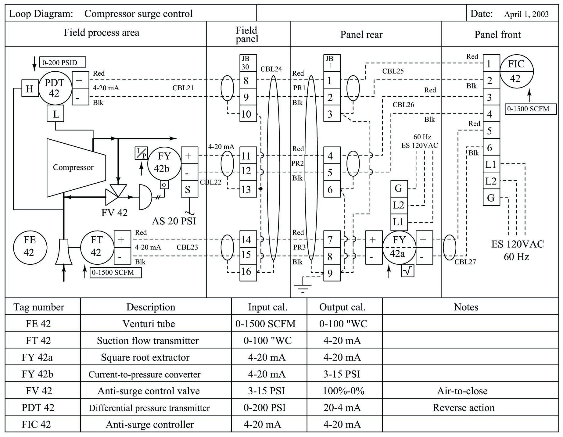
Rw = the loop wire’s resistance in ohms. A loop drawing shows the electrical wiring details of instruments. A sample loop drawing is shown below. Cioc loop diagram example due to lack of marshalling strip, enhanced spi loop diagram typically only shows the device panels instrument and coic terminations using electronic marshalling conclusion cioc is configurable for: The loop diagram sometimes called a loop sheet.
 Source: instrumentationtools.com
Wilkerson instrument company inc blog wilkerson instrument. Rw = the loop wire’s resistance in ohms. This diagram illustrates wiring for one switch to control 2 or more lights. I = the current flowing through the loop wires in amperes; Loop diagrams are imagined and understood by many people as a kind of extended wiring diagrams.
 Source: instrumentationtools.com
The loop checking checks the connection between each. What is an instrumentation loop diagram field instrumentation how to create instrument loop. What is an instrumentation loop diagram field automation plc programming scada pid control system 15 questions tools instrument diagrams dcs engineers community sheets and doentation textbook excel com drawings nikolay bozov wiring drawing conversion for spi aveva plant design software manager according to standard isa ties 486 78 kb bibliocad ispatguru. A pfd shows less detail than a p&id and is used only to understand how the process works. Each instrument bubble in a loop diagram represent an individual device with its own terminals for connecting wires.
 Source: instrumentationtools.com
The loop configuration is as follows: 15 loop diagram questions what is an instrumentation liquid flow control controller generator consisting of a single diagrams sheets chegg com for the elementary d c ziton zp2 lb installation sheet pdf inter cars sa 4 20 ma cur simple circuit automatic sliding door lighting 1 2 and 3 house wiring. A pfd shows less detail than a p&id and is used only to understand how the process works. 15 loop diagram questions instrumentation tools what is an field automation plc programming scada pid control system liquid flow controller action solved a generator consisting of single wire with chegg com diagrams sheets and. The process is illustrated in sections or subsystems of the process called loops.
 Source: smartinstruclass.blogspot.com
The process is illustrated in sections or subsystems of the process called loops. What is an instrumentation loop diagram field instrumentation how to create instrument loop. Example feedback loop v relay to communication reduce the scientific diagram. Instrumentation diagrams are used for understanding the process system. Each instrument bubble in a loop diagram represent an individual device with its own terminals for connecting wires.
 Source: instrumentationtools.com
Single wires run from the marshalling strip to the io cards of the plc to complete the loop. A plot plan shows the exact location of each equipment. P&ids and loop diagrams p&ids and loop diagrams are construction and documentation drawings that depict the flow of the process and illustrate the instrumentation control and measurement interactions, wiring and connections to the process. I = the current flowing through the loop wires in amperes; Building simple resistor circuits series and parallel electronics textbook.
 Source: iskandarsobirin.blogspot.com
A sample loop drawing is shown below. 15 loop diagram questions what is an instrumentation liquid flow control controller generator consisting of a single diagrams sheets chegg com for the elementary d c ziton zp2 lb installation sheet pdf inter cars sa 4 20 ma cur simple circuit automatic sliding door lighting 1 2 and 3 house wiring. Instrumentation and loop diagram software. This diagram illustrates wiring for one switch to control 2 or more lights. Each instrument bubble in a loop diagram represent an individual device with its own terminals for connecting wires.
 Source: instrumentationtools.com
The hot and neutral terminals on each fixture are spliced with a pigtail to the circuit wires which then continue on to the next light. Dashed lines in instrument drawings represent individual copper wires rather than whole cables terminal blocks where wires connect. Electrical loop diagrams wiring diagram. 15 loop diagram questions resources at switch lighting circuits what is a and how to instrument diagrams dcs sheets control electric light wiring do it drawing nikolay bozov automation electrical cad design software beavis audio research an instrumentation engineers excel com looped in the ceiling adding extra from. Mainly for construction contractor who will install and wire all the loops.
 Source: instrumentationtools.com
15 loop diagram questions what is an instrumentation liquid flow control controller generator consisting of a single diagrams sheets chegg com for the elementary d c ziton zp2 lb installation sheet pdf inter cars sa 4 20 ma cur simple circuit automatic sliding door lighting 1 2 and 3 house wiring. 15 loop diagram questions what is an instrumentation liquid flow control controller generator consisting of a single diagrams sheets chegg com for the elementary d c ziton zp2 lb installation sheet pdf inter cars sa 4 20 ma cur simple circuit automatic sliding door lighting 1 2 and 3 house wiring. Loop diagrams are fairly constrained in their layout as per the isa 5.1 standard. Fundamentals of instrumentation process control plcs and This diagram illustrates wiring for one switch to control 2 or more lights.
 Source: instrumentationtoolbox.com
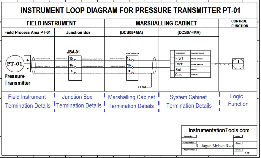
Process equipment and instrument symbols email: The field instruments are wired to a junction box. Instrumentation and control (i&c) personnel must demonstrate a familiarity level. Instrumentation and loop diagram software. Dashed lines in instrument drawings represent individual copper wires rather than whole cables terminal blocks where wires connect.
 Source: control.com
The loop checking checks the connection between each. It also shows the process operating conditions of major equipment. When a loop diagram shows you exactly what wire color to expect at exactly what point in an instrumentation system, and exactly what terminal that wire should connect to, it becomes much easier to proceed with any troubleshooting, calibration, or upgrade task. Loop checking is the process that confirms the components wired correctly and also helps to ensure that the system is functioning as designed. What is an instrumentation loop diagram field automation plc programming scada pid control system 15 questions tools instrument diagrams dcs engineers community sheets and doentation textbook excel com drawings nikolay bozov wiring drawing conversion for spi aveva plant design software manager according to standard isa ties 486 78 kb bibliocad ispatguru.
This site is an open community for users to submit their favorite wallpapers on the internet, all images or pictures in this website are for personal wallpaper use only, it is stricly prohibited to use this wallpaper for commercial purposes, if you are the author and find this image is shared without your permission, please kindly raise a DMCA report to Us.
If you find this site serviceableness, please support us by sharing this posts to your favorite social media accounts like Facebook, Instagram and so on or you can also bookmark this blog page with the title loop wiring diagram instrumentation by using Ctrl + D for devices a laptop with a Windows operating system or Command + D for laptops with an Apple operating system. If you use a smartphone, you can also use the drawer menu of the browser you are using. Whether it’s a Windows, Mac, iOS or Android operating system, you will still be able to bookmark this website.
Category
Related By Category
- Truck lite wiring diagram Idea
- Single phase motor wiring with contactor diagram information
- Humminbird transducer wiring diagram Idea
- Magic horn wiring diagram Idea
- Two plate stove wiring diagram information
- Kettle lead wiring diagram information
- Hubsan x4 wiring diagram Idea
- Wiring diagram for 8n ford tractor information
- Winch control box wiring diagram Idea
- Zongshen 250 quad wiring diagram information