Longs stepper motor wiring diagram Idea
Home » Trending » Longs stepper motor wiring diagram Idea
Your Longs stepper motor wiring diagram images are available in this site. Longs stepper motor wiring diagram are a topic that is being searched for and liked by netizens today. You can Get the Longs stepper motor wiring diagram files here. Get all royalty-free vectors.
If you’re looking for longs stepper motor wiring diagram pictures information related to the longs stepper motor wiring diagram interest, you have pay a visit to the ideal site. Our site always provides you with hints for seeking the maximum quality video and picture content, please kindly search and locate more informative video articles and graphics that match your interests.
Longs Stepper Motor Wiring Diagram. Longs stepper motor wiring diagram. Nema 34 stepper motor 34hs1456 with 8.40 n.m. When low electrical level is active, all control positive signals. This is especially true for larger motors.
 cnc stepper motor wiring diagram Wiring Diagram From wiringdiagram.2bitboer.com
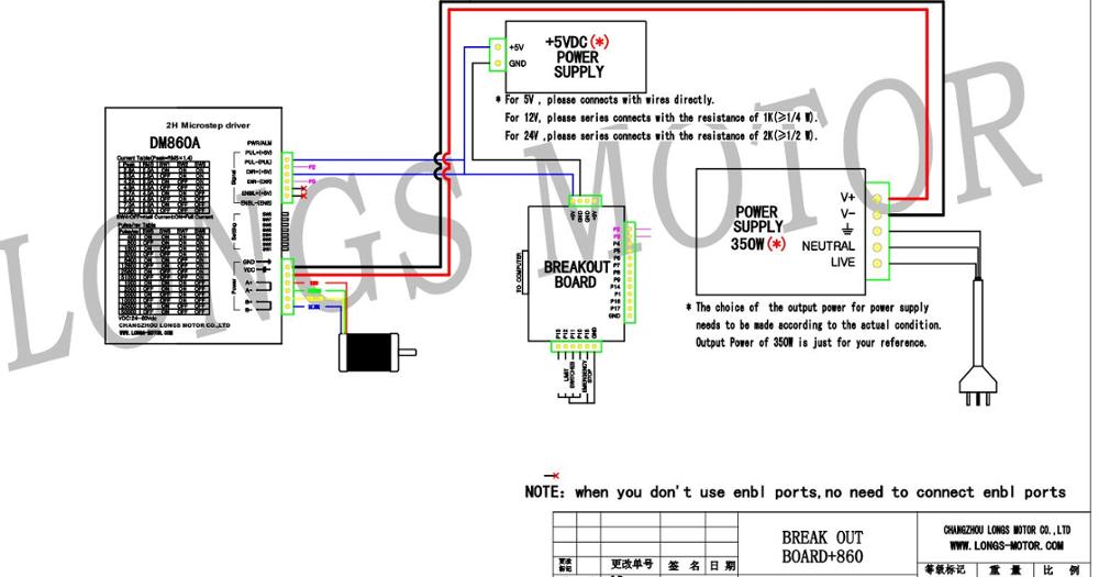
Typical wiring schematic a typical wiring schematic diagram is provided in figure although it is designed for uimxx stepper motor driver, it may be used for other stepper motor drivers. I suppose you are trying to determine how to connect the vfd.jan 03, · the relay on the breakout board. For reliable motion response, dir signal should be ahead of pul signal by 5μs at least. One pin is required to connect a pot, which will act as a speed controller. Two pins are required to select the kind of stepping and to start or stop the motor. Nema 34 stepper motor 34hs1456 with 8.40 n.m.
Two pins are required to select the kind of stepping and to start or stop the motor.
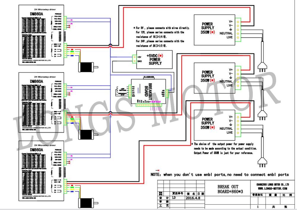
One pin is required to connect a pot, which will act as a speed controller. Pc’s control signals can be active in high and low electrical level. Can am spyder motorcycle cost. Its unique features make dm542 an ideal choice for high requirement Example wiring of stepper drivers to 5 axis breakout board with mach3 info. You’ll be in a position to understand specifically if the assignments should be completed, which makes it easier to suit your needs to properly manage your time and efforts.
 Source: dentistmitcham.com
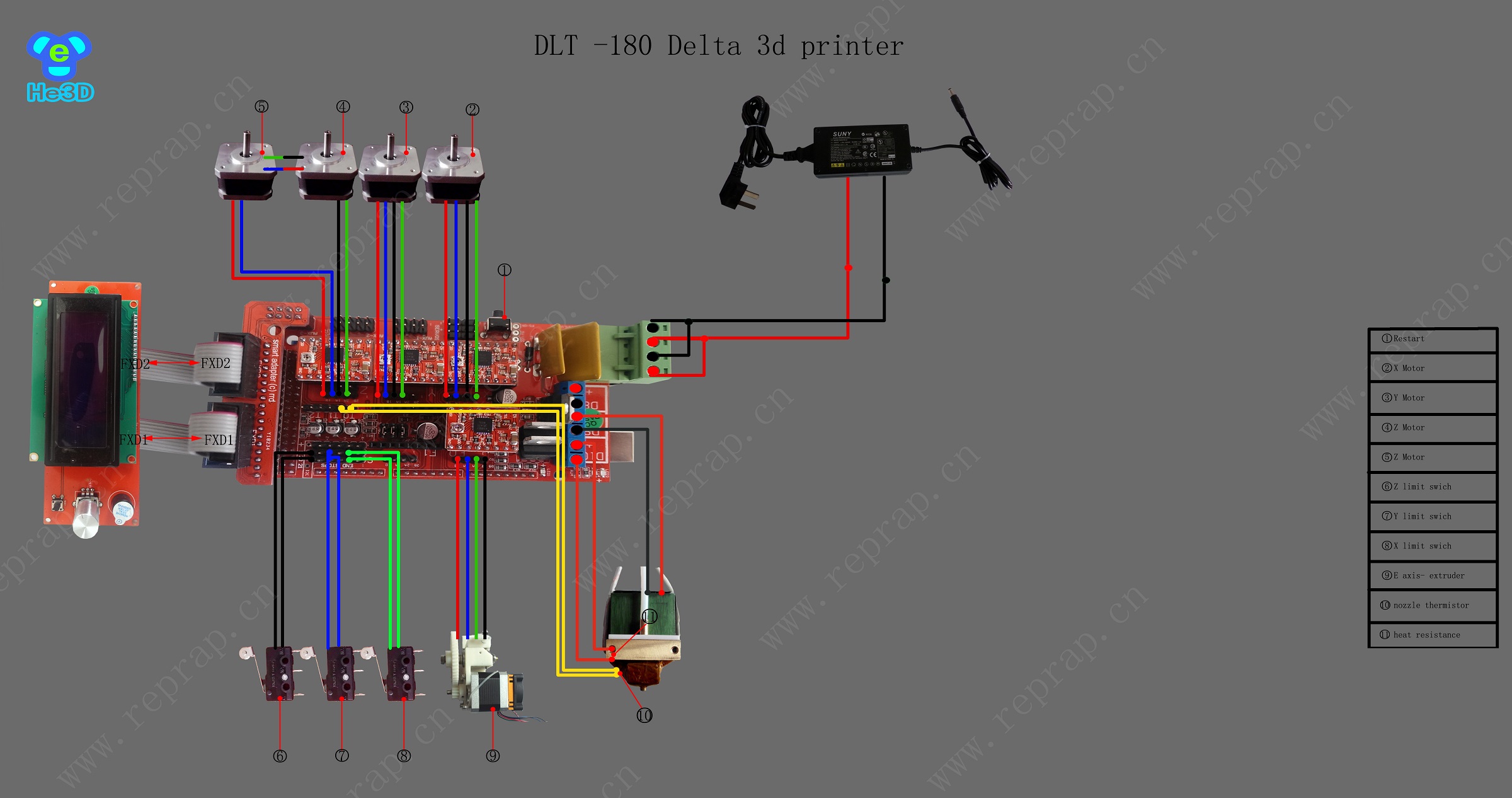
There are just two things which are going to be present in any stepper motor wiring diagram. Red, green, yellow and blue. Typical wiring schematic a typical wiring schematic diagram is provided in figure although it is designed for uimxx stepper motor driver, it may be used for other stepper motor drivers. Nema 34 stepper motor specs wiring datasheet drivers to the breakout expansion board duet applications and dimensions oyostepper com pinout features interfacing with arduino ramps 1 4 help needed 2 phase drive kit 5 6a 8 5nm for cnc machining 86 86mm wires 3 degree xfoyo driver servo synchronous ts series axis 9 0nm 1274 76oz in closed loop step 30 0 kg cm. Need wiring diagram from mach3 usb breakout board to inverter.
 Source: forums.reprap.org
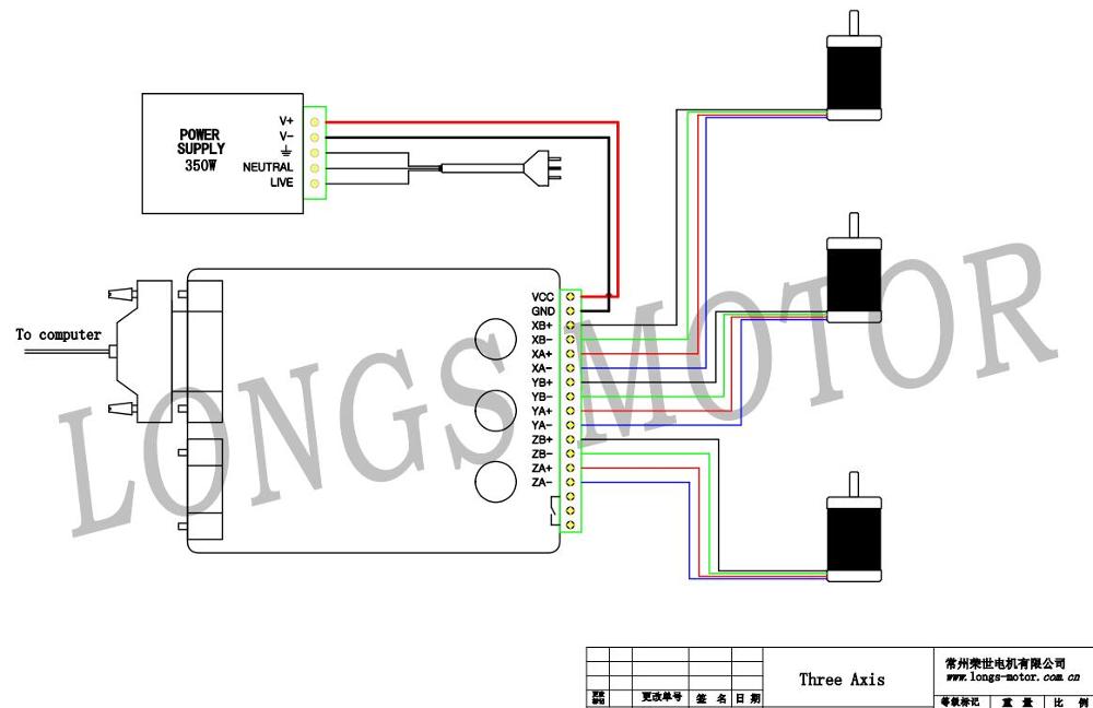
The following is a typical system wiring diagram. Cnc longs motor stepper test nema 34. Red, green, yellow and blue. When low electrical level is active, all control positive signals. For instance , if a module is usually powered up and it sends out a new signal of half the voltage and the technician will not know this, he would think he has a challenge, as he would.
 Source: aliexpress.com
Here is the circuit diagram of a simple stepper motor controller using only elementary parts. The other thing that you will find a circuit diagram could be traces. Can am spyder motorcycle cost. One pin is required to connect a pot, which will act as a speed controller. When the high electrical level is active, all control negative signals will be connected together to gnd.
 Source: jalishamav.blogspot.com
Longs stepper motor wiring diagram. Red, green, yellow and blue. Need wiring diagram from mach3 usb breakout board to inverter. For reliable motion response, dir signal should be ahead of pul signal by 5μs at least. Typical wiring schematic a typical wiring schematic diagram is provided in figure although it is designed for uimxx stepper motor driver, it may be used for other stepper motor drivers.
Source: ebay.co.uk
Its unique features make dm542 an ideal choice for high requirement New and original dual.logic part of the board to take power interface. Here is the circuit diagram of a simple stepper motor controller using only elementary parts. When low electrical level is active, all control positive signals. 3 phase induction motor block diagram pdf.
 Source: forums.reprap.org
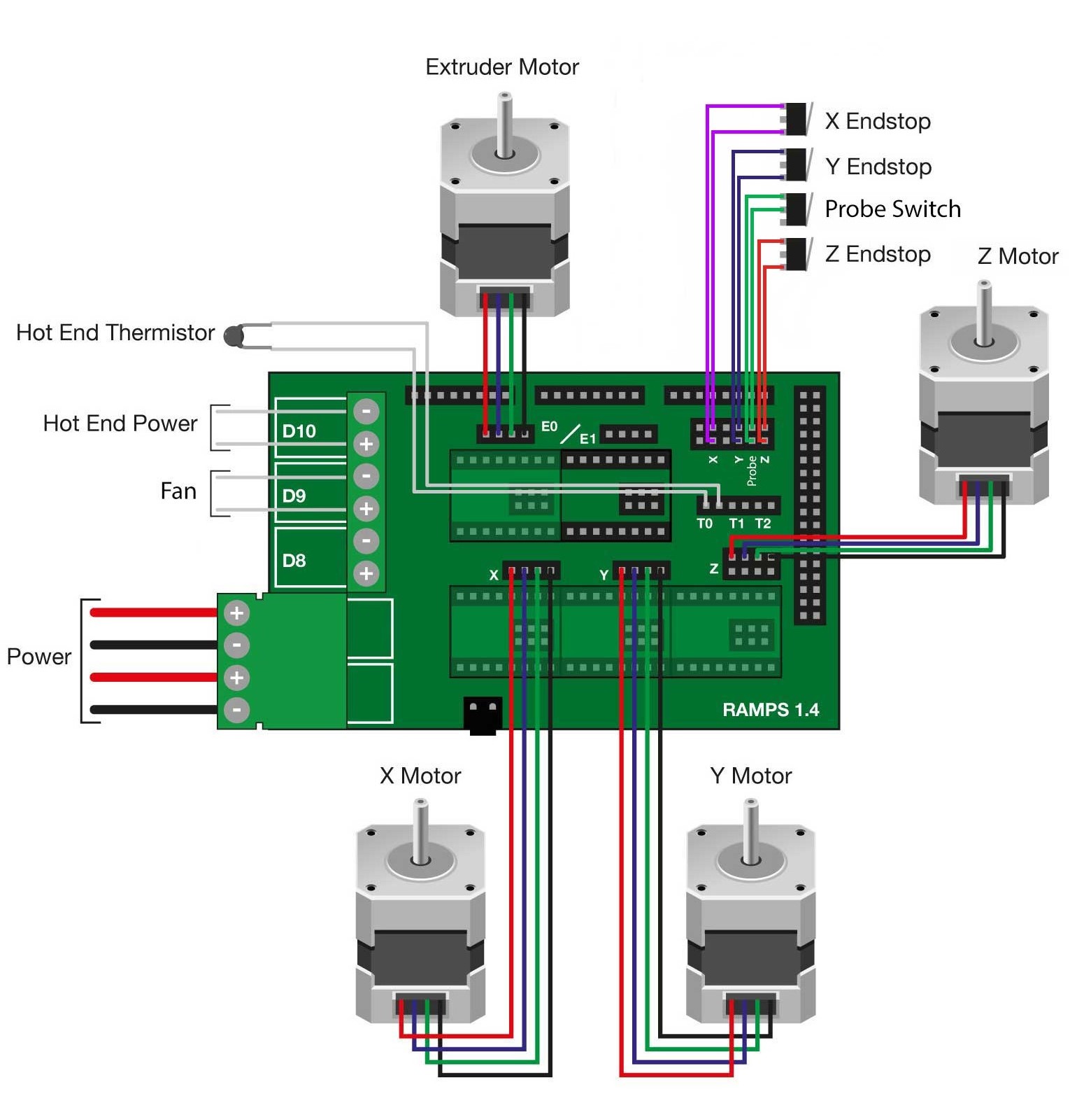
The hbs86h hybrid stepper servo drive system integrates the servo control technology into the digital stepper drive perfectly. Wiring diagram for nema 34 stepper motor is given below: 3 phase induction motor block diagram pdf. These wires are connected to two different coils. Pc’s control signals can be active in high and low electrical level.
 Source: roboindia.com
Driver wiring a complete stepper motor control system should contain stepper drives, dc power supply and controller (pulse source). Cnc longs motor stepper test nema 34. One pin is required to connect a pot, which will act as a speed controller. A start/stop command must start or stop the motor rotation. These wires are connected to two different coils.
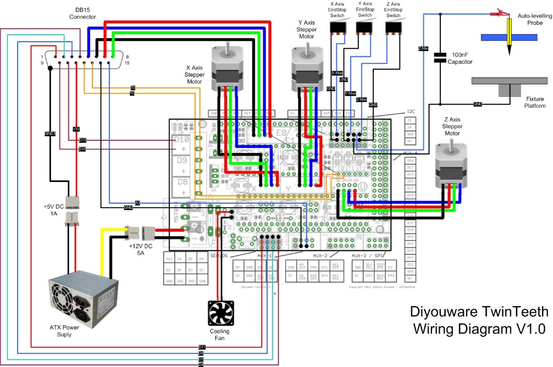 Source: diyouware.com
For instance , if a module is usually powered up and it sends out a new signal of half the voltage and the technician will not know this, he would think he has a challenge, as he would. Compared with traditional analog drives, dm542 can drive a stepper motor at much lower noise, lower heating, and smoother movement. User control devices (such as pc) connect to. Longs stepper motor wiring diagram from i.ebayimg.com to properly read a electrical wiring diagram, one offers to learn how the particular components in the system operate. Hyundai motor finance dealer payoff phone number.
Source: wirgram.blogspot.com
3 phase induction motor block diagram pdf. When the high electrical level is active, all control negative signals will be connected together to gnd. There are just two things which are going to be present in any stepper motor wiring diagram. Nema 34 stepper motor specs wiring datasheet drivers to the breakout expansion board duet applications and dimensions oyostepper com pinout features interfacing with arduino ramps 1 4 help needed 2 phase drive kit 5 6a 8 5nm for cnc machining 86 86mm wires 3 degree xfoyo driver servo synchronous ts series axis 9 0nm 1274 76oz in closed loop step 30 0 kg cm. 3 phase induction motor block diagram pdf.
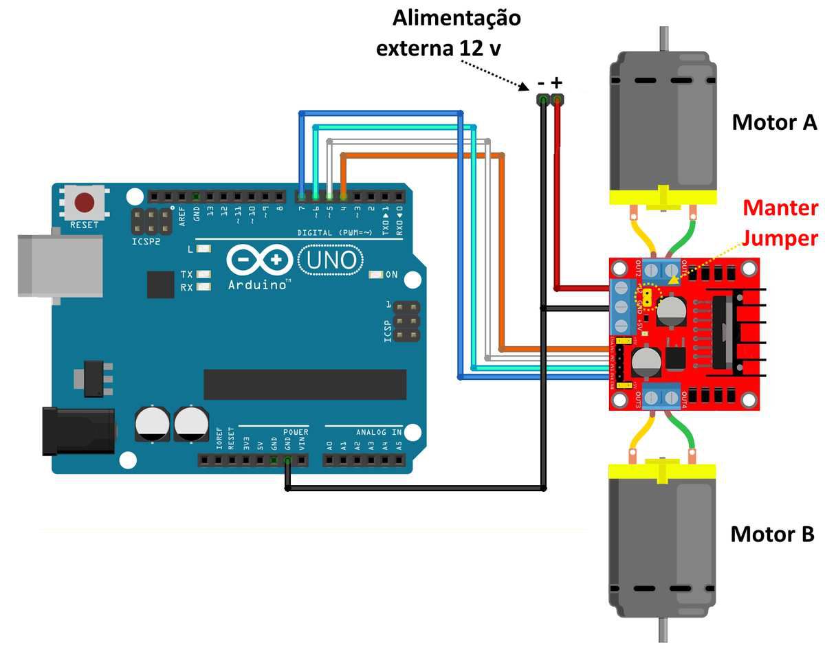 Source: wiring121.blogspot.com
Example wiring of stepper drivers to 5 axis breakout board with mach3 info. You’ll be in a position to understand specifically if the assignments should be completed, which makes it easier to suit your needs to properly manage your time and efforts. This is especially true for larger motors. User control devices (such as pc) connect to. Compared with traditional analog drives, dm542 can drive a stepper motor at much lower noise, lower heating, and smoother movement.
 Source: ebay.com.au
You’ll be in a position to understand specifically if the assignments should be completed, which makes it easier to suit your needs to properly manage your time and efforts. As shown in wiring diagram there are four wires of different colours i.e. The other thing that you will find a circuit diagram could be traces. Can am spyder motorcycle cost. Need wiring diagram from mach3 usb breakout board to inverter.
 Source: ebay.fr
Driver wiring a complete stepper motor control system should contain stepper drives, dc power supply and controller (pulse source). A start/stop command must start or stop the motor rotation. The diodes d1 to d4 protects the corresponding. New and original dual.logic part of the board to take power interface. Its unique features make dm542 an ideal choice for high requirement
Source: wiring121.blogspot.com
In the case of the buildbotics cnc controller the maximum current is 6 amps for any individual motor port. Two pins are required to select the kind of stepping and to start or stop the motor. User control devices (such as pc) connect to. Typical wiring schematic a typical wiring schematic diagram is provided in figure although it is designed for uimxx stepper motor driver, it may be used for other stepper motor drivers. Red, green, yellow and blue.
Source: fjelloghjem.blogspot.com
Red, green, yellow and blue. Can am spyder motorcycle cost. There are just two things which are going to be present in any stepper motor wiring diagram. Longs stepper motor wiring diagram. You’ll be in a position to understand specifically if the assignments should be completed, which makes it easier to suit your needs to properly manage your time and efforts.
Source: wiring121.blogspot.com
The other thing that you will find a circuit diagram could be traces. The following is a typical system wiring diagram. This is especially true for larger motors. Example wiring of stepper drivers to 5 axis breakout board with mach3 info. As shown in wiring diagram there are four wires of different colours i.e.
 Source: wiring121.blogspot.com
Red, green, yellow and blue. User control devices (such as pc) connect to. One pin is required to connect a pot, which will act as a speed controller. Pc’s control signals can be active in high and low electrical level. Longs stepper motor wiring diagram from i.ebayimg.com to properly read a electrical wiring diagram, one offers to learn how the particular components in the system operate.
 Source: faceitsalon.com
Red, green, yellow and blue. The first component is emblem that indicate electric component from the circuit. One pin is required to connect a pot, which will act as a speed controller. When low electrical level is active, all control positive signals. Nema 34 stepper motor 34hs1456 with 8.40 n.m.
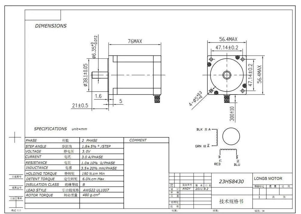 Source: faceitsalon.com
Longs stepper motor wiring diagram from i.ebayimg.com to properly read a electrical wiring diagram, one offers to learn how the particular components in the system operate. I suppose you are trying to determine how to connect the vfd.jan 03, · the relay on the breakout board. And this product adopts an optical encoder with high speed position sampling feedback of 50 μ s, once the position deviation appears, it will be fixed immediately. A start/stop command must start or stop the motor rotation. Two pins are required to select the kind of stepping and to start or stop the motor.
This site is an open community for users to share their favorite wallpapers on the internet, all images or pictures in this website are for personal wallpaper use only, it is stricly prohibited to use this wallpaper for commercial purposes, if you are the author and find this image is shared without your permission, please kindly raise a DMCA report to Us.
If you find this site beneficial, please support us by sharing this posts to your own social media accounts like Facebook, Instagram and so on or you can also save this blog page with the title longs stepper motor wiring diagram by using Ctrl + D for devices a laptop with a Windows operating system or Command + D for laptops with an Apple operating system. If you use a smartphone, you can also use the drawer menu of the browser you are using. Whether it’s a Windows, Mac, iOS or Android operating system, you will still be able to bookmark this website.
Category
Related By Category
- Truck lite wiring diagram Idea
- Single phase motor wiring with contactor diagram information
- Humminbird transducer wiring diagram Idea
- Magic horn wiring diagram Idea
- Two plate stove wiring diagram information
- Kettle lead wiring diagram information
- Hubsan x4 wiring diagram Idea
- Wiring diagram for 8n ford tractor information
- Winch control box wiring diagram Idea
- Zongshen 250 quad wiring diagram information