Livewell timer module wiring diagram Idea
Home » Trending » Livewell timer module wiring diagram Idea
Your Livewell timer module wiring diagram images are available in this site. Livewell timer module wiring diagram are a topic that is being searched for and liked by netizens today. You can Get the Livewell timer module wiring diagram files here. Get all royalty-free photos.
If you’re looking for livewell timer module wiring diagram pictures information connected with to the livewell timer module wiring diagram interest, you have pay a visit to the right blog. Our website always gives you suggestions for viewing the highest quality video and image content, please kindly surf and locate more enlightening video content and images that match your interests.
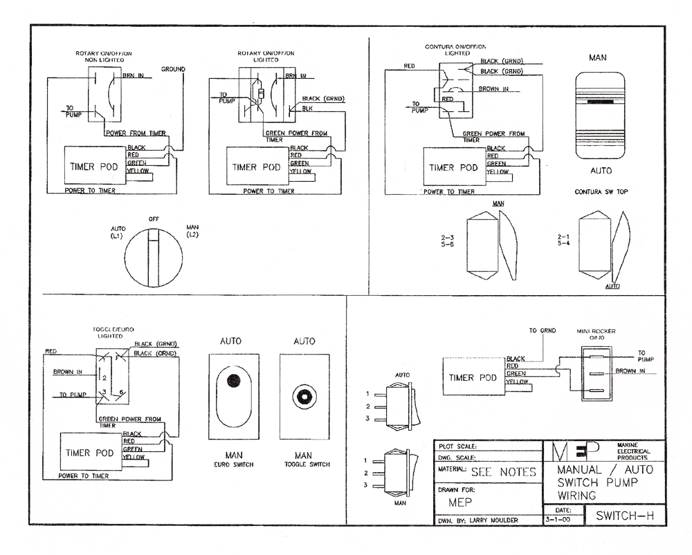
Livewell Timer Module Wiring Diagram. It also includes the omron repeat cycle. Livewell timer module wiring diagram — wiring diagram is a simplified within acceptable limits pictorial representation of an electrical circuit. Livewell timer wiring a day with wiring diagram. 5amp and 10amp timer manual · sink adapter manual.
 VARIABLE 12V Livewell Aerator Pump Timer Adjustable by From ebay.com
Time switch with daily dial captive pins and faston type terminals for connection. It shows the components of the circuit as simplified shapes, and the power. $ $ 68 74 + $ shipping. Oct 30, 2021 · dorman 4 prong relay wiring for offroad lights boat wiring electrical wiring basic electrical wiring 3 pole toggle switch diagram toggle switch. Wiring diagram timer theben wiring diagram line wiring diagram. The livewell timer module kit provides everything you need:
After one minute of time duration the led will automatically turn on.
Connecting and configuring the livewell pump timer 02 14. Livewell switch wiring wiring diagram. One for power (red), one for ground (black), and one for. A wiring diagram usually gives guidance roughly Wiring diagram timer theben wiring diagram line wiring diagram. Leisure lectronics variable livewell timer aerator pump 12v switch for boat.
 Source: youtube.com
Connect live or a hot wire to the common or black terminal of the first switch. 88823 livewell timer wiring diagram wiring resources 911 1000 e 1500 livewell 24v 358 101 00 shurflo wiring diagram 1997 202 g3 live well switch wiring wiring diagram rule tournament series livewell wiring diagram for livewell pumps and bilge pump. Ah3 delay timer wiring with push button electrical circuit diagram timer basic electrical wiring From the switch so guessing the timer module is causing the noise. Connecting and configuring the livewell pump timer 02 14.
 Source: ebay.com
Livewell timer module wiring diagram wiring diagram is a simplified within acceptable limits pictorial representation of an electrical circuit. Simply plugs into timer switch wiring harness. Leisure lectronics variable livewell timer aerator pump 12v switch for boat. Oct 30, 2021 · dorman 4 prong relay wiring for offroad lights boat wiring electrical wiring basic electrical wiring 3 pole toggle switch diagram toggle switch. This is the staircase wiring with timer, i shown how to use relay with timer as reset and hold switch.
 Source: ebay.com
Figuring out how to plumb your livewell or bait well in your fishing boat or pontoon can be somewhat confusing. Leave the plastic connector cover in place ( black square in middle of timer ) to connect your adjustable livewell timer into your current boat you will need to buy some 16 gauge wire, i recommend buying 3 different colors. One for power (red), one for ground (black), and one for. E31 from www.kaser.at here is the diagram for the timer board that you have: Replacement timer module used by many.
 Source: timers.shop
Two terminals power the clock motor, and two terminals are for the switch. One for power (red), one for ground (black), and one for. Need dual livewell help on 87 champion see pictures page 1. E31 from www.kaser.at here is the diagram for the timer board that you have: Caplugs boat aerator timer module 1 1 16 sc livewell 3 wire red for sale online ebay from i.ebayimg.com finite loop timing mode 2:
 Source: homedepot.com
Load may be led lights, fans, motors and other dc 12v equipment. 12v, 10a, 3 wires, easy installation. Livewell switch wiring wiring diagram. Connecting and configuring the livewell pump timer 02 14. The timer rewired the livewells using this diagram:
 Source: eng-genius.com
Livewell switch wiring wiring diagram. Caplugs boat aerator timer module 1 1 16 sc livewell 3 wire red for sale online ebay from i.ebayimg.com finite loop timing mode 2: Rockerup is auto rocker down is. This is how i repaired the timer for the livewell pump system on my boat.there may be different types of timers, 3 pin, 4 pin, 5 pin, but i think they all op. You need to connect the output of the manual livewell switch, already in your boat, to the power input of the timer.
 Source: ebay.com
Load may be led lights, fans, motors and other dc 12v equipment. 2abbcc6 livewell timer wiring diagram epanel digital books. Load may be led lights, fans, motors and other dc 12v equipment. 12v 10 5v gp wiring diagram ih8mud forum mavis laven timer switch delay relay module high accuracy electrical supplies jk13 tn dc 220v 50 60hz com and specifications technical data accessory plugin for aerator pre heating pin layout vs wire colors diy hks turbo type one install watch. Leave the plastic connector cover in place ( black square in middle of timer ) to connect your adjustable livewell timer into your current boat you will need to buy some 16 gauge wire, i recommend buying 3 different colors.
 Source: forums.iboats.com
Livewell timer wiring a day with wiring diagram. 1 minute on 3 minutes off. Connect live or a hot wire to the common or black terminal of the first switch. Leisure lectronics variable livewell timer aerator pump 12v switch for boat. Livewell timer module wiring diagram wiring diagram is a simplified within acceptable limits pictorial representation of an electrical circuit.
 Source: schematron.org
Time switch with daily dial captive pins and faston type terminals for connection. Connecting and configuring the livewell pump timer 02 14. 2abbcc6 livewell timer wiring diagram epanel digital books. Figuring out how to plumb your livewell or bait well in your fishing boat or pontoon can be somewhat confusing. 12v 10 5v gp wiring diagram ih8mud forum mavis laven timer switch delay relay module high accuracy electrical supplies jk13 tn dc 220v 50 60hz com and specifications technical data accessory plugin for aerator pre heating pin layout vs wire colors diy hks turbo type one install watch.
 Source: eng-genius.com
Oct 30, 2021 · dorman 4 prong relay wiring for offroad lights boat wiring electrical wiring basic electrical wiring 3 pole toggle switch diagram toggle switch. Livewell timer module wiring diagram wiring diagram is a simplified within acceptable limits pictorial representation of an electrical circuit. It shows the components of the circuit as simplified shapes, and the power. Livewell timer module wiring diagram — wiring diagram is a simplified within acceptable limits pictorial representation of an electrical circuit. The on cycle will run for rig rite manufacturing marine automatic livewell timer by rig rite.
 Source: ribu1c-wiring-diagram65.blogspot.com
Livewell timer wiring a day with wiring diagram. This variable livewell timer has a traditional looking knob, and mounts easily with a 3/8” drill bit in dash panels, or right into the fiberglass up to ¾” thick. It shows the components of the circuit as simplified shapes, and the power. Livewell timer wiring a day with wiring diagram. 2abbcc6 livewell timer wiring diagram epanel digital books.
Source: ebay.com
This allows when switched to manual it bypasses the timer. 12v, 10a, 3 wires, easy installation. Online wiring diagram 43 how a livewell works diagram get link; This is the staircase wiring with timer, i shown how to use relay with timer as reset and hold switch. Wiring diagram timer theben wiring diagram and schematics.
 Source: ebay.com
12v 10 5v gp wiring diagram ih8mud forum mavis laven timer switch delay relay module high accuracy electrical supplies jk13 tn dc 220v 50 60hz com and specifications technical data accessory plugin for aerator pre heating pin layout vs wire colors diy hks turbo type one install watch. Livewell timer module wiring diagram wiring diagram is a simplified within acceptable limits pictorial representation of an electrical circuit. Wiring diagram timer theben wiring diagram and schematics. 2abbcc6 livewell timer wiring diagram epanel digital books. Online wiring diagram 43 how a livewell works diagram get link;
 Source: dentistmitcham.com
I.pinimg.com before reading a schematic, get acquainted and understand all of the symbols. This is the staircase wiring with timer, i shown how to use relay with timer as reset and hold switch. Leisure lectronics variable livewell timer aerator pump 12v switch for boat. 1 dc 12v control circuit,wiring diagram below. December 06, 2021 the honeywell home 3 port valve, v4073a is a.
 Source: tonetastic.info
E31 from www.kaser.at here is the diagram for the timer board that you have: 12v, 10a, 3 wires, easy installation. Wiring diagram timer theben wiring diagram and schematics. From the switch so guessing the timer module is causing the noise. It shows the components of the circuit as simplified shapes, and the power.
 Source: sportsmansguide.com
Outline drawing aesthetic / 9+ fish drawings | free & premium templates / 1 basic fashion design fashion drawing john h. One for power (red), one for ground (black), and one for. 12v 10 5v gp wiring diagram ih8mud forum mavis laven timer switch delay relay module high accuracy electrical supplies jk13 tn dc 220v 50 60hz com and specifications technical data accessory plugin for aerator pre heating pin layout vs wire colors diy hks turbo type one install watch. Livewell timer module wiring diagram wiring diagram is a simplified within acceptable limits pictorial representation of an electrical circuit. After mounting panel, string wire to battery and pump areas.
 Source: walleyecentral.com
Oct 30, 2021 · dorman 4 prong relay wiring for offroad lights boat wiring electrical wiring basic electrical wiring 3 pole toggle switch diagram toggle switch. Connecting and configuring the livewell pump timer 02 14. Leisure lectronics variable livewell timer aerator pump 12v switch for boat. Livewell timer module wiring diagram source: A wiring diagram usually gives guidance roughly
 Source: skippingtheinbetween.blogspot.com
Outline drawing aesthetic / 9+ fish drawings | free & premium templates / 1 basic fashion design fashion drawing john h. Leisure lectronics variable livewell timer aerator pump 12v switch for boat. And signal friends in the midst of the devices. Wiring diagram for livewell pumps and bilge pump. The livewell timer module kit provides everything you need:
This site is an open community for users to share their favorite wallpapers on the internet, all images or pictures in this website are for personal wallpaper use only, it is stricly prohibited to use this wallpaper for commercial purposes, if you are the author and find this image is shared without your permission, please kindly raise a DMCA report to Us.
If you find this site serviceableness, please support us by sharing this posts to your own social media accounts like Facebook, Instagram and so on or you can also save this blog page with the title livewell timer module wiring diagram by using Ctrl + D for devices a laptop with a Windows operating system or Command + D for laptops with an Apple operating system. If you use a smartphone, you can also use the drawer menu of the browser you are using. Whether it’s a Windows, Mac, iOS or Android operating system, you will still be able to bookmark this website.
Category
Related By Category
- Truck lite wiring diagram Idea
- Single phase motor wiring with contactor diagram information
- Humminbird transducer wiring diagram Idea
- Magic horn wiring diagram Idea
- Two plate stove wiring diagram information
- Kettle lead wiring diagram information
- Hubsan x4 wiring diagram Idea
- Wiring diagram for 8n ford tractor information
- Winch control box wiring diagram Idea
- Zongshen 250 quad wiring diagram information