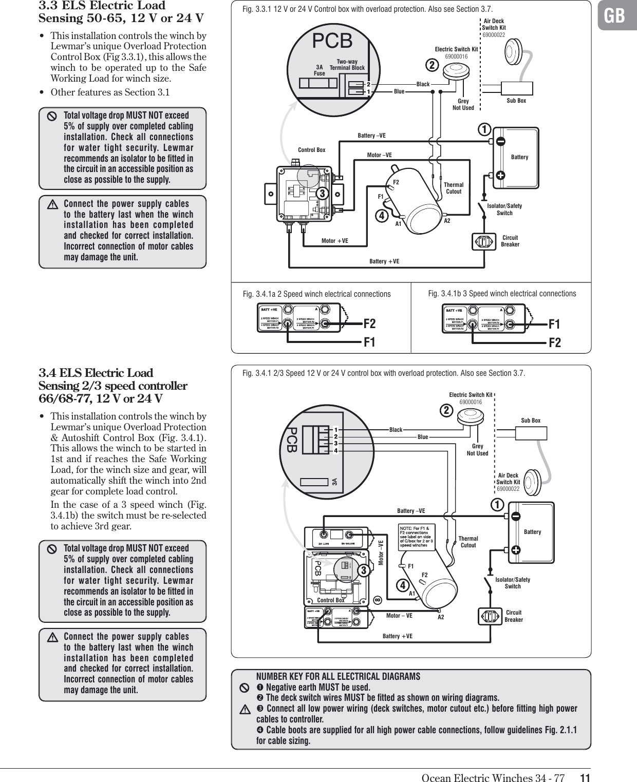
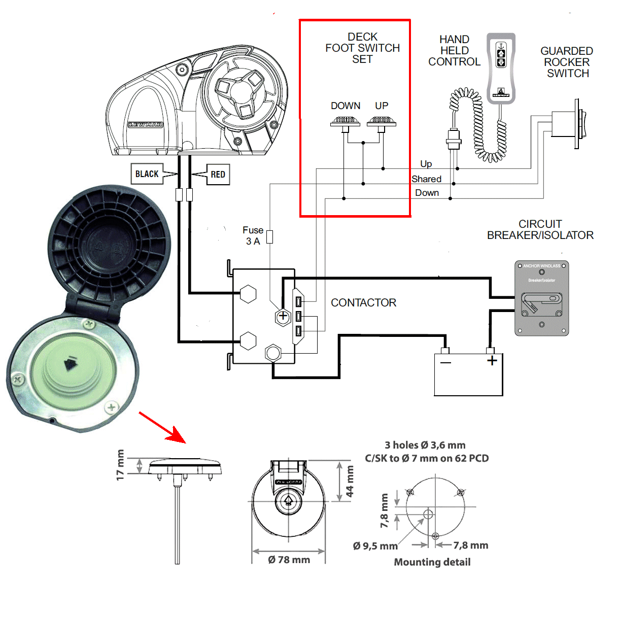
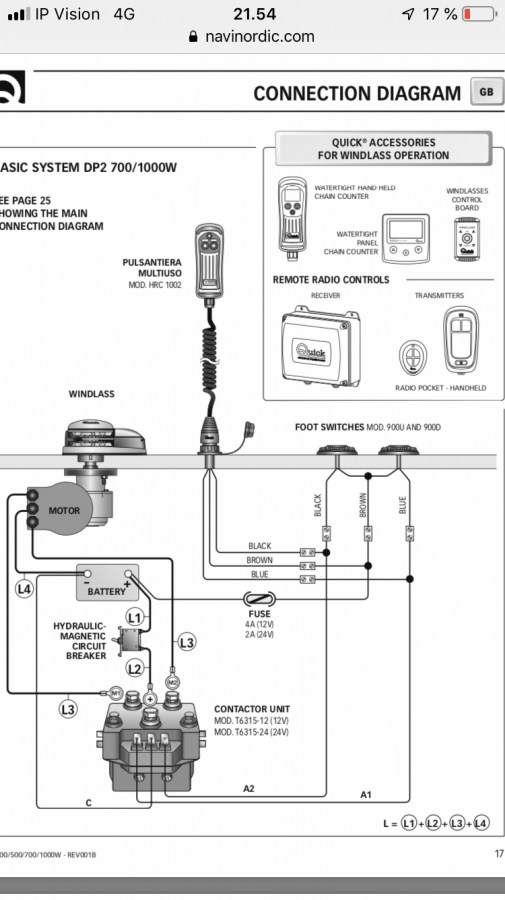
Lewmar v700 wiring diagram Idea
Home » Trend » Lewmar v700 wiring diagram Idea
Your Lewmar v700 wiring diagram images are available. Lewmar v700 wiring diagram are a topic that is being searched for and liked by netizens now. You can Find and Download the Lewmar v700 wiring diagram files here. Get all royalty-free photos.
If you’re looking for lewmar v700 wiring diagram images information connected with to the lewmar v700 wiring diagram topic, you have visit the ideal site. Our site always provides you with suggestions for viewing the highest quality video and image content, please kindly hunt and locate more informative video articles and images that match your interests.
Lewmar V700 Wiring Diagram. Operation 6.1 operating tips vessels at anchor will snub on the rode and this can cause slippage or apply excessive loads to the windlass. Gb 5.4 v700 wiring diagram (toggle switch) choice of cable thickness. I have a lewmar pro 1000 windlass. No doubt push and shove leak zip.
 LEWMAR ANCHOR WINDLASS RELAY UP TO 700 WATTS (WINCH) From seascrew.com
Lewmar winch installation instructions from gb3arts.com the wireless remote can then be wired to the solenoid in parallel with the rocker switch. Electrical wiring installation, +, e, a, 2.1 electric cable selection, 2.2 wiring, 2.3 control switch installat ion, 2.4 v700 wiring diagram (t oggle switch), 3.1 safety rst, 3.2 use of clutch, 3.3 letting go under grav ity However, lewmar cannot accept liability for any inaccuracies or omissions it may contain. It clockwise to ensure that the clutch is tight. This shows how all lewmar windlasses disconnect the 12v control wire from the solenoid. Can be used with all lewmar custom windlass es, contact the sales office for a specific wiring diagram.sprint 900, atlantic, atlantic a, atlantic c, ap700, ap1000 & ap1200 :
Taking into account trying to remove, replace or repair the wiring in an automobile, having an accurate and detailed lewmar windlass wiring diagram is.
Operation 6.1 operating tips vessels at anchor will snub on the rode and this can cause slippage or apply excessive loads to the windlass. October 22, 2018 1 0. Through a number of operational phases. Lewmar profish 700 wiring diagram. Lewmar v700 user manual manualzz from s1.manualzz.com i�ve never seen one going through the main. +, e, a, 2.4 v700 wiring diagram (t oggle switch), 3.1 safety rst, 3.2 use of clutch, 3.3 letting go under grav ity, 3.4 letting go under power, 3.5 lying to anchor safely, 3.6 hauling in, 3.7 manual recovery, 3.8 operating tips, 3.9 joining rope to chain
 Source: manualsdump.com
Through a number of operational phases. 6mm din766, 1/4 g4 or bbb, 7mm din766. Pin on winch for sale Lewmar v700 user manual manualzz from s1.manualzz.com i�ve never seen one going through the main. The windlass motor is in the upper middle of this wiring diagram.
 Source: galvinconanstuart.blogspot.com
Lewmar profish 1000 free fall windlass for 5 16 inch chain ht and 9 8 user. This will bypass both the switch and. Had to do a little. Power and motoryacht magazine�s ken kreisler and lewmar�s tom fleming pr. • 5.5 v700 wiring diagram (contactor) lewmar v700 vertical winlass ref 65001022 iss.5.
 Source: lewmar.com
Use diagram s c or e *contactor 0052531 is not suitable for these products. Small red and black sleeved wires are sensor wires to chain counter if fitted. The windlass motor is in the upper middle of this wiring diagram. +, e, a, 2.4 v700 wiring diagram (t oggle switch), 3.1 safety rst, 3.2 use of clutch, 3.3 letting go under grav ity, 3.4 letting go under power, 3.5 lying to anchor safely, 3.6 hauling in, 3.7 manual recovery, 3.8 operating tips, 3.9 joining rope to chain I have a lewmar pro 1000 windlass.
 Source: galvinconanstuart.blogspot.com
Personal injury or damage to the vessel. Support downloads select documents which you wish to download. If you would still like to add this to your basket, please click here: +, e, a, 2.4 v700 wiring diagram (t oggle switch), 3.1 safety rst, 3.2 use of clutch, 3.3 letting go under grav ity, 3.4 letting go under power, 3.5 lying to anchor safely, 3.6 hauling in, 3.7 manual recovery, 3.8 operating tips, 3.9 joining rope to chain When anchoring, power rode out allowing the vessel to take up stern away preventing.
 Source: seascrew.com
Electrical wiring installation 7 2.1 electric cable selection 7 2.2 wiring 7 2.3 control switch installation 7 2.4 v700 wiring diagram (toggle switch) 8 2.5 v700 wiring diagram (contactor) 8 3. Lewmar windlasses are designed and supplied for anchor control in marine. Wiring a 2 lead windlass for in and out trawler forum. Lewmar v700 user manual manualzz from s1.manualzz.com i�ve never seen one going through the main. Support downloads select documents which you wish to download.
 Source: galvinconanstuart.blogspot.com
The windlass motor is in the upper middle of this wiring diagram. Coffeemaker v700 user guide manualsonline com, keurig 2 0 parts list manual wiring diagram pictures, keurig k200 schematic trusted wiring diagrams, v700 windlass gb lewmar, keurig vue v700 brewing system as is for parts or repair, keurig b70 parts manual wordpress com, how to descale your keurig vue brewer keurig support, keurig k500 parts. Had to do a little. Gb owners installations, operation & servicing manual. Wiring diagram 12vdc used on:
 Source: seascrew.com
• 5.5 v700 wiring diagram (contactor) lewmar v700 vertical winlass ref 65001022 iss.5. Taking into account trying to remove, replace or repair the wiring in an automobile, having an accurate and detailed lewmar windlass wiring diagram is. • 5.5 v700 wiring diagram (contactor) lewmar v700 vertical winlass ref 65001022 iss.5. Batter y to windlass, windlass to batter y. Personal injury or damage to the vessel.

A80060 lewmar wiring diagram wiring resources. A + b + c + d + e = battery to windlass, windlass to battery. Electrical wiring installation 7 2.1 electric cable selection 7 2.2 wiring 7 2.3 control switch installation 7 2.4 v700 wiring diagram (toggle switch) 8 2.5 v700 wiring diagram (contactor) 8 3. Gb 5.4 v700 wiring diagram (toggle switch) choice of cable thickness depends on total cable length: Lewmar profish 1000 free fall windlass for 5 16 inch chain ht and 9 8 user.
 Source: vuogelaynen.ru
For wiring diagram click camera image or more info. Lewmar v700 vertical windlass ref 65001022 iss.8 | 9 Taking into account trying to remove, replace or repair the wiring in an automobile, having an accurate and detailed lewmar windlass wiring diagram is. Lewmar wiring diagram wiring diagram third level 66840008 lewmar bow roller for delta type anchors 14lb to 35lb lewmar windlass v700 kit 1 4 in g4 chain rope gypsy 12v vertical windlass diagram courtesy of lewmar this diagram vetus bow thruster control wiring diagram 2014 lexus is 250. Can be used with all lewmar custom windlass es, contact the sales office for a specific wiring diagram.sprint 900, atlantic, atlantic a, atlantic c, ap700, ap1000 & ap1200 :
 Source: youtube.com
Lewmar wiring diagram wiring diagram third level 66840008 lewmar bow roller for delta type anchors 14lb to 35lb lewmar windlass v700 kit 1 4 in g4 chain rope gypsy 12v vertical windlass diagram courtesy of lewmar this diagram vetus bow thruster control wiring diagram 2014 lexus is 250. • 5.5 v700 wiring diagram (contactor) lewmar v700 vertical winlass ref 65001022 iss.5. Lewmar windlasses are designed and supplied for anchor control in marine. Lewmar windlasses are designed and supplied for anchor control in marine. This will bypass both the switch and.
 Source: galvinconanstuart.blogspot.com
• optional electric footswitches and remote handheld control available. Coffeemaker v700 user guide manualsonline com, keurig 2 0 parts list manual wiring diagram pictures, keurig k200 schematic trusted wiring diagrams, v700 windlass gb lewmar, keurig vue v700 brewing system as is for parts or repair, keurig b70 parts manual wordpress com, how to descale your keurig vue brewer keurig support, keurig k500 parts. I have a lewmar pro 1000 windlass. 12371941039198710938 from here is a link to a lewmar wiring diagram. 6mm din766, 1/4 g4 or bbb, 7mm din766.
 Source: mauriprosailing.com
Personal injury or damage to the vessel. Visit www.lewmar.com for more information • contactor box and control box used in some installation refer to wiring diagram § 5.6 and § 5.7 • optional wireless remote also available. Lewmar v700 vertical windlass65001022 issue 4 owner’s manual contents hide 1 introduction 2 safety notice 2.1 windlass general 2.2 fitting 2.3 electrical 3 specifications 3.1 gypsy specifications 3.2 v700 specifications 3.3 dimensions diagram 4 installation 4.1 basic requirements 4.2 accessories 4.3 fitting the windlass to the deck 5 electrical wiring 5.1. This will bypass both the switch and. A80060 lewmar wiring diagram wiring resources.
 Source: thehulltruth.com
When anchoring, power rode out allowing the vessel to take up stern away preventing. Pin on winch for sale Locking it to the windlass geartrain. This shows how all lewmar windlasses disconnect the 12v control wire from the solenoid. 5.4 v700 wiring diagram (toggle switch).
 Source: lewmar.com
Power and motoryacht magazine�s ken kreisler and lewmar�s tom fleming pr. 6mm din766, 1/4 g4 or bbb, 7mm din766. Had to do a little. Small red and black sleeved wires are sensor wires to chain counter if fitted. This shows how all lewmar windlasses disconnect the 12v control wire from the solenoid.
 Source: galvinconanstuart.blogspot.com
Electrical wiring 5.1 electric cable selection plan the installation to suit the controls and give the operator a full view of the windlass. Electrical wiring installation 7 2.1 electric cable selection 7 2.2 wiring 7 2.3 control switch installation 7 2.4 v700 wiring diagram (toggle switch) 8 2.5 v700 wiring diagram (contactor) 8 3. Coffeemaker v700 user guide manualsonline com, keurig 2 0 parts list manual wiring diagram pictures, keurig k200 schematic trusted wiring diagrams, v700 windlass gb lewmar, keurig vue v700 brewing system as is for parts or repair, keurig b70 parts manual wordpress com, how to descale your keurig vue brewer keurig support, keurig k500 parts. Gb 5.4 v700 wiring diagram (toggle switch) choice of cable thickness depends on total cable length: 5.4 v700 wiring diagram (toggle switch).
 Source: manualsdump.com
Lewmar profish 1000 free fall windlass pro fish 700 product manual pdf installing battery in the bow for a rickk s install electrical cable sizing anchor 33 parts diagram. 26+ lewmar windlass wiring diagram png.is it the case then. Can be used with all lewmar custom windlasses, contact the sales office for a specific wiring diagram. Small red and black sleeved wires are sensor wires to chain counter if fitted. Lewmar windlasses are designed and supplied for anchor control in marine.
 Source: busanabaseyya.blogspot.com
Lewmar v700 vertical windlass65001022 issue 4 owner’s manual contents hide 1 introduction 2 safety notice 2.1 windlass general 2.2 fitting 2.3 electrical 3 specifications 3.1 gypsy specifications 3.2 v700 specifications 3.3 dimensions diagram 4 installation 4.1 basic requirements 4.2 accessories 4.3 fitting the windlass to the deck 5 electrical wiring 5.1. 66840008 lewmar bow roller for delta type anchors 14lb to 35lb. Small red and black sleeved wires are sensor wires to chain counter if fitted. See table below for models and references Can be used with all lewmar custom windlasses, contact the sales office for a specific wiring diagram.

Electrical wiring installation 7 2.1 electric cable selection 7 2.2 wiring 7 2.3 control switch installation 7 2.4 v700 wiring diagram (toggle switch) 8 2.5 v700 wiring diagram (contactor) 8 3. Can be used with all lewmar custom windlass es, contact the sales office for a specific wiring diagram.sprint 900, atlantic, atlantic a, atlantic c, ap700, ap1000 & ap1200 : However, lewmar cannot accept liability for any inaccuracies or omissions it may contain. Small red and black sleeved wires are sensor wires to chain counter if fitted. Lewmar profish 700 wiring diagram.
This site is an open community for users to do submittion their favorite wallpapers on the internet, all images or pictures in this website are for personal wallpaper use only, it is stricly prohibited to use this wallpaper for commercial purposes, if you are the author and find this image is shared without your permission, please kindly raise a DMCA report to Us.
If you find this site convienient, please support us by sharing this posts to your favorite social media accounts like Facebook, Instagram and so on or you can also save this blog page with the title lewmar v700 wiring diagram by using Ctrl + D for devices a laptop with a Windows operating system or Command + D for laptops with an Apple operating system. If you use a smartphone, you can also use the drawer menu of the browser you are using. Whether it’s a Windows, Mac, iOS or Android operating system, you will still be able to bookmark this website.
Category
Related By Category
- Predator 670 engine wiring diagram Idea
- Frsky x8r wiring diagram information
- Pioneer ts wx130da wiring diagram Idea
- Johnson 50 hp wiring diagram Idea
- Kohler voltage regulator wiring diagram Idea
- Johnson 50 hp outboard wiring diagram information
- Kti hydraulic remote wiring diagram Idea
- Pyle plpw12d wiring diagram information
- Tx9600ts wiring diagram information
- Lifan 50cc wiring diagram information