Lennox prodigy wiring diagram Idea
Home » Trend » Lennox prodigy wiring diagram Idea
Your Lennox prodigy wiring diagram images are ready in this website. Lennox prodigy wiring diagram are a topic that is being searched for and liked by netizens today. You can Find and Download the Lennox prodigy wiring diagram files here. Find and Download all royalty-free photos and vectors.
If you’re looking for lennox prodigy wiring diagram pictures information related to the lennox prodigy wiring diagram topic, you have visit the right blog. Our website always gives you suggestions for seeing the highest quality video and image content, please kindly surf and find more informative video content and images that fit your interests.
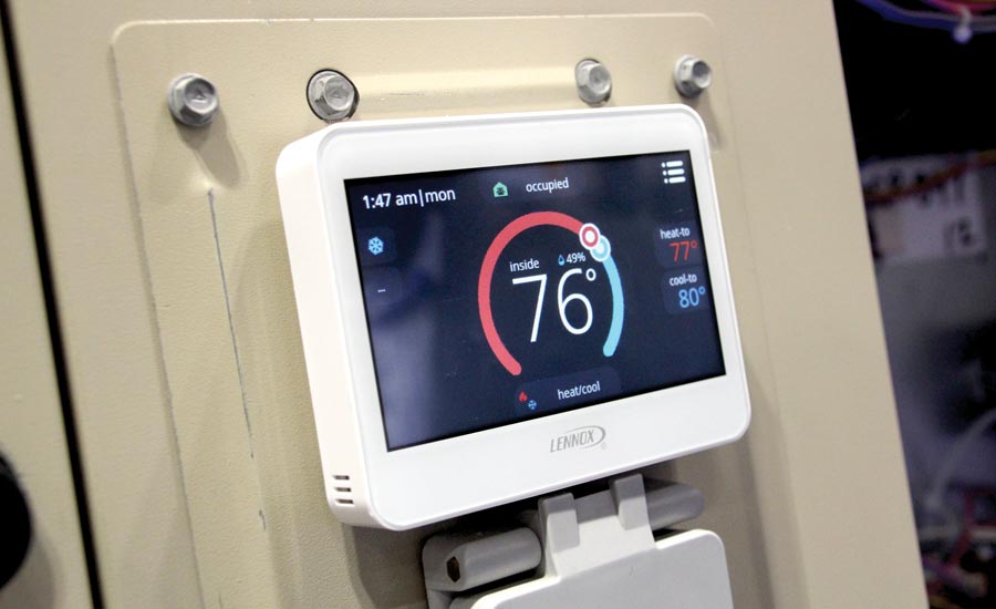
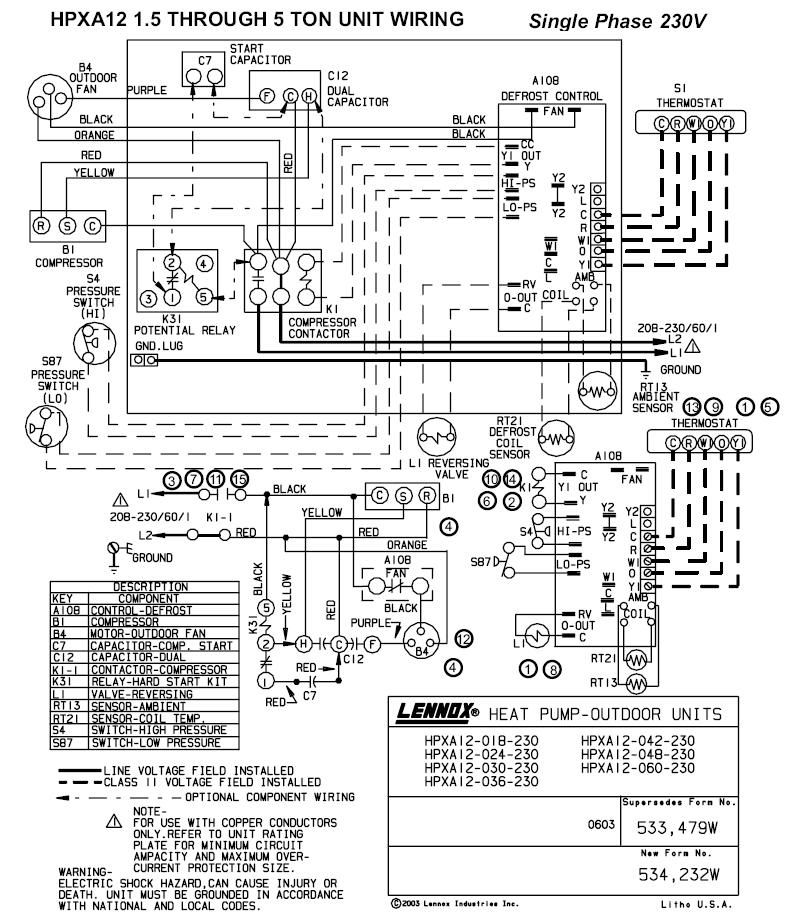
Lennox Prodigy Wiring Diagram. Page 25 wiring diagrams (036, 048, 060 units) description component monitor, phase protection control, main panel lennox panel, motor control a169 compressor 1 motor,. Also see for lennox prodigy m2. Detailed composite wiring diagrams for control systems showing factory. I do not have a lennox customer number.
 Wiring Diagram For Outdoor Thermostat Lennox Furnace Intended From therun2016.com
15 general application (2 heat and 3 cool heat pump)16. 14 general application (2 heat and 3 cool). (wiring diagrams are also shown beginning on page 59 of this manual.) note − if electric heat strips are used with an icomfort −enabled air handler, the strips must be configured on the air handler control (ahc) board before beginning the discovery sequence below. After all wiring connections are made, apply power to the system. The room sensor wiring diagram key number is a2. Lennox furnace thermostat wiring diagram collection.
Lennox control board wiring diagram free download.
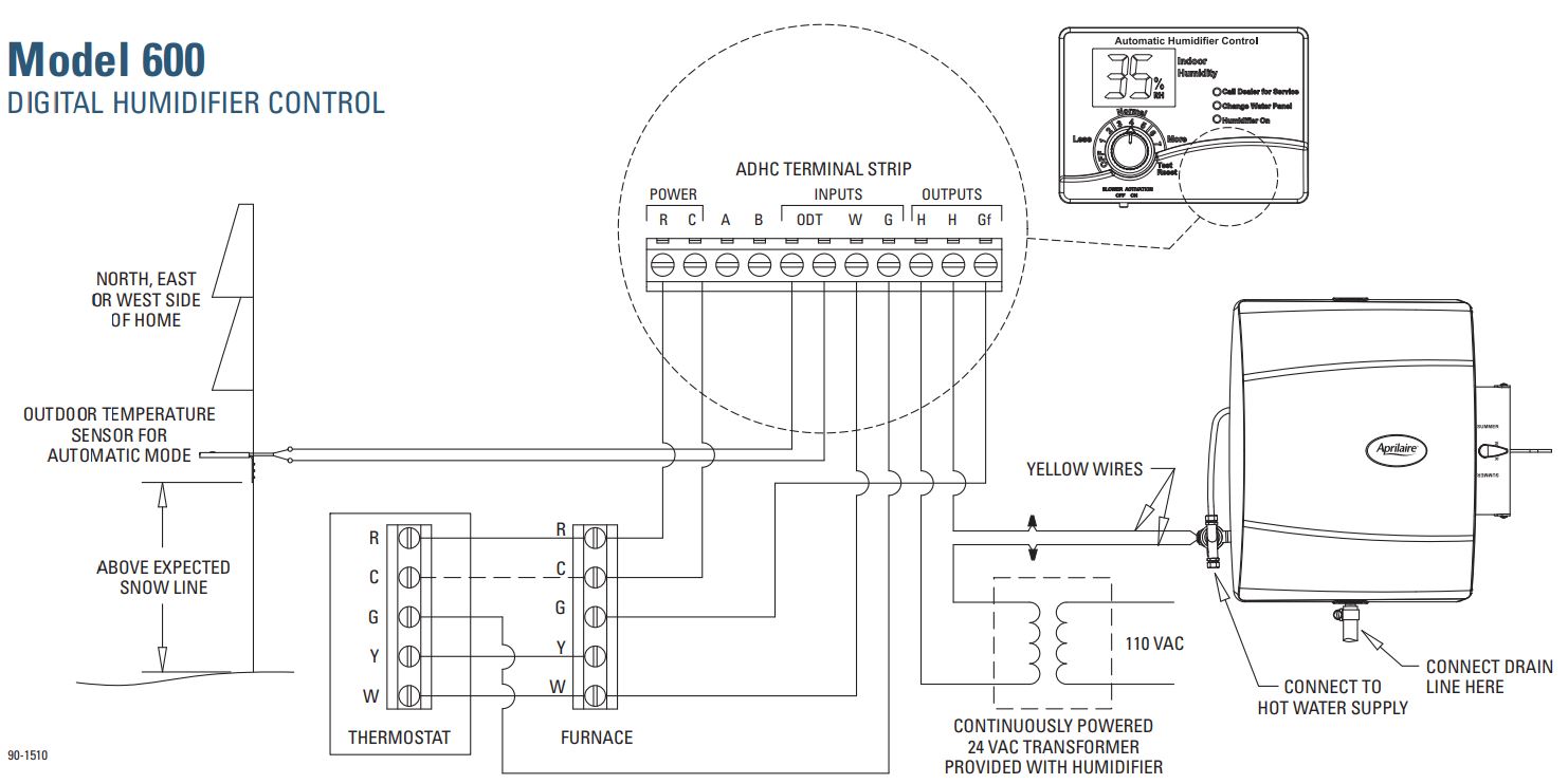
Bus termination 120 ohm resistor on last interface in chain. Default values device max_master 127 device max_info_frames 1 device object_identifier mac address device object_name “lennox_m4_ + mac address for mstp or last octet of ip address for bip Each unit tracks the runtime of every major component and records the date and time when service or maintenance is performed. 1 − wiring diagram sticker 6 − #10−16 x 5/8” screws note: The prodigy looks like it gets the combustion air from where the convection fan feeds in. A wiring diagram is a streamlined traditional photographic depiction of an electrical circuit.
 Source: wiringschemas.blogspot.com
Consult instructions before installation and use of this appliance. I have checked voltage and continuity and they both indicate that the. A lennox 80mgf series furnace has an internal control board with a led diagnostic light feature. The room air sensor is wired to the prodigy. (marked gnd and tmp on the field wiring t ermination.
 Source: schematicandwiringdiagram.blogspot.com
Page 25 wiring diagrams (036, 048, 060 units) description component monitor, phase protection control, main panel lennox panel, motor control a169 compressor 1 motor,. After all wiring connections are made, apply power to the system. Dallas, texas, usa retain these instructions for future reference these instructions are intended as a general guide and do not supersede local codes in any way. Related manuals for lennox prodigy m2. Lennox prodigy m2 application manual 104 pages.
 Source: wiringschemas.blogspot.com
3.novar 3051 ddc not included. Lennox control board wiring diagram free download. Units are shipped from the factory configured for control. Prodigy® 2.0 (m3 unit controller) c3 replacement control kit (10x87) prodigy® 2.0 (m3 unit controller) firmware update [limited 3 years on lennox environ® coil system] 5.
![[MX_2369] Prodigy Thermostat Wire Diagram Prodigy Circuit [MX_2369] Prodigy Thermostat Wire Diagram Prodigy Circuit](https://static-resources.imageservice.cloud/19277938/prodigy-tr-86-thermostat-wiring-diagram-most-wrg-1835wiring.jpg) Source: dupl.wedab.mohammedshrine.org
Source: dupl.wedab.mohammedshrine.org
Chevy gmc brake control install billavista com trailer controller tech article by installing an electric on 2007 2013 gm full size truck or present suv etrailer wiring diagram and newer new body styles r p carriages cargo utility dump equipment car haulers enclosed trailers in chicago ottawa dekalb joliet il for tekonsha powertrac prodigy. A wiring diagram is a simplified conventional photographic depiction of an electric circuit. I�m having issues with 2 lennox lgh156h4bs2y rtus that are equipped with m2 prodigy board, and connect to a lennox ncp controller both have 3 zones each. [limited 3 years on lennox environ® coil system] 5. I do not have a lennox customer number.
 Source: mckenneyelectric.com
Related manuals for lennox prodigy m2. 1 − wiring diagram sticker 6 − #10−16 x 5/8” screws note: In the same manner, if the unit has a compressor I have checked voltage and continuity and they both indicate that the. (wiring diagrams are also shown beginning on page 59 of this manual.) note − if electric heat strips are used with an icomfort −enabled air handler, the strips must be configured on the air handler control (ahc) board before beginning the discovery sequence below.
 Source: nebulouslustres.blogspot.com
1 − wiring diagram sticker 6 − #10−16 x 5/8” screws note: Replaced older trane units which had smoke detectors installed in the return duct and tied into fire alarm system. Prodigy® control system makes setup, troubleshooting and servicing easier than ever. Application manual for lennox prodigy 2.0. Lennox control board wiring diagram free download.
 Source: diychatroom.com
The room air sensor is wired to the prodigy. In the same manner, if the unit has a compressor Default values device max_master 127 device max_info_frames 1 device object_identifier mac address device object_name “lennox_m4_ + mac address for mstp or last octet of ip address for bip This product is used in several different models. Application manual for lennox prodigy 2.0.
 Source: therun2016.com
Bus termination 120 ohm resistor on last interface in chain. Prodigy® (m1 and m2 unit controllers) frequency ask questions; If the unit contains a blower delay, the delay will keep the blower from immediately starting. A wiring diagram is a streamlined traditional photographic depiction of an electrical circuit. Wiring (diagram) wiring (diagram) cat # :
![[MX_2369] Prodigy Thermostat Wire Diagram Prodigy Circuit [MX_2369] Prodigy Thermostat Wire Diagram Prodigy Circuit](https://static-resources.imageservice.cloud/17178172/infinite-switch-wiring-diagram-wiring-diagram-database.gif) Source: dupl.wedab.mohammedshrine.org
Source: dupl.wedab.mohammedshrine.org
Warning improper installation, adjustment, alteration, service or The unit controller intelligently operates the rooftop unit to help ensure reliability, maximum efficiency and comfort. 15 general application (2 heat and 3 cool heat pump)16. We’ve made it easy for you to find the resources you need, including product brochures and owner’s manuals. The default control type is wired thermostat.
 Source: khanborgotsoi9.blogspot.com
A wiring diagram is a streamlined traditional photographic depiction of an electrical circuit. (marked gnd and tmp on the field wiring t ermination. Each unit tracks the runtime of every major component and records the date and time when service or maintenance is performed. A wiring diagram is a simplified conventional photographic depiction of an electric circuit. We ve made it easy for you to find the resources you need including product brochures and owner s manuals.
![[MX_2369] Prodigy Thermostat Wire Diagram Prodigy Circuit [MX_2369] Prodigy Thermostat Wire Diagram Prodigy Circuit](https://static-assets.imageservice.cloud/316294/nissan-titan-electric-brake-controller-kwakufavour.jpg) Source: dupl.wedab.mohammedshrine.org
Source: dupl.wedab.mohammedshrine.org
Consult instructions before installation and use of this appliance. Consult instructions before installation and use of this appliance. Repeater is required for longer lengths. Lennox manuals gray cooling man air my conservator iii g16 q3 75 furnace i have a the gas valve 3 pulse no c terminal g20re series manualzz loud and noisy 90ugf g16r heater repair. In the same manner, if the unit has a compressor
 Source: sitzone.blogspot.com
I�m having issues with 2 lennox lgh156h4bs2y rtus that are equipped with m2 prodigy board, and connect to a lennox ncp controller both have 3 zones each. The unit controller intelligently operates the rooftop unit to help ensure reliability, maximum efficiency and comfort. Lennox hearth products dealer for approved pellet fuels. The room sensor wiring diagram key number is a2. Lennox control board wiring diagram free download.
![[MX_2369] Prodigy Thermostat Wire Diagram Prodigy Circuit [MX_2369] Prodigy Thermostat Wire Diagram Prodigy Circuit](https://static-resources.imageservice.cloud/19277933/prodigy-wiring-diagram-electric-mx-tl.jpg) Source: dupl.wedab.mohammedshrine.org
Source: dupl.wedab.mohammedshrine.org
Page 25 wiring diagrams (036, 048, 060 units) description component monitor, phase protection control, main panel lennox panel, motor control a169 compressor 1 motor,. If the unit contains a blower delay, the delay will keep the blower from immediately starting. [limited 5 years on high performance economizers] 7. (wiring diagrams are also shown beginning on page 59 of this manual.) note − if electric heat strips are used with an icomfort −enabled air handler, the strips must be configured on the air handler control (ahc) board before beginning the discovery sequence below. 3.novar 3051 ddc not included.
 Source: wiringschemas.blogspot.com
15 general application (2 heat and 3 cool heat pump)16. A short push of the pushbutton will bypass this delay and the blower will operate. Consult authorities who have jurisdiction before installation. Bus termination 120 ohm resistor on last interface in chain. 15 general application (2 heat and 3 cool heat pump)16.
 Source: achrnews.com
This product is used in several different models. (wiring diagrams are also shown beginning on page 59 of this manual.) note − if electric heat strips are used with an icomfort −enabled air handler, the strips must be configured on the air handler control (ahc) board before beginning the discovery sequence below. I have checked voltage and continuity and they both indicate that the. This appliance is for outdoor installation only mbar (high) mbar (low) 50 63 z803140 54.1 storage when units are delivered on site they are not always. Installed six, new lennox rtu�s, the store bought and supplied the equipment.
 Source: wiringschemas.blogspot.com
The room air sensor is wired to the prodigy. 15 general application (2 heat and 3 cool heat pump)16. In the same manner, if the unit has a compressor If the unit contains a blower delay, the delay will keep the blower from immediately starting. Repeater is required for longer lengths.
 Source: nestwiringdiagram.com
Installed six, new lennox rtu�s, the store bought and supplied the equipment. I have checked voltage and continuity and they both indicate that the. Lennox 27m19, 94l63 or 68m25 max. Chevy gmc brake control install billavista com trailer controller tech article by installing an electric on 2007 2013 gm full size truck or present suv etrailer wiring diagram and newer new body styles r p carriages cargo utility dump equipment car haulers enclosed trailers in chicago ottawa dekalb joliet il for tekonsha powertrac prodigy. A lennox 80mgf series furnace has an internal control board with a led diagnostic light feature.
 Source: doityourself.com
[limited 3 years on lennox environ® coil system] 5. Simply narrow your search using the options below. Lennox 27m19, 94l63 or 68m25 max. Installed six, new lennox rtu�s, the store bought and supplied the equipment. I have checked voltage and continuity and they both indicate that the.
This site is an open community for users to do submittion their favorite wallpapers on the internet, all images or pictures in this website are for personal wallpaper use only, it is stricly prohibited to use this wallpaper for commercial purposes, if you are the author and find this image is shared without your permission, please kindly raise a DMCA report to Us.
If you find this site beneficial, please support us by sharing this posts to your own social media accounts like Facebook, Instagram and so on or you can also bookmark this blog page with the title lennox prodigy wiring diagram by using Ctrl + D for devices a laptop with a Windows operating system or Command + D for laptops with an Apple operating system. If you use a smartphone, you can also use the drawer menu of the browser you are using. Whether it’s a Windows, Mac, iOS or Android operating system, you will still be able to bookmark this website.
Category
Related By Category
- Predator 670 engine wiring diagram Idea
- Frsky x8r wiring diagram information
- Pioneer ts wx130da wiring diagram Idea
- Johnson 50 hp wiring diagram Idea
- Kohler voltage regulator wiring diagram Idea
- Johnson 50 hp outboard wiring diagram information
- Kti hydraulic remote wiring diagram Idea
- Pyle plpw12d wiring diagram information
- Tx9600ts wiring diagram information
- Lifan 50cc wiring diagram information