Lennox icomfort wiring diagram Idea
Home » Trend » Lennox icomfort wiring diagram Idea
Your Lennox icomfort wiring diagram images are ready. Lennox icomfort wiring diagram are a topic that is being searched for and liked by netizens today. You can Get the Lennox icomfort wiring diagram files here. Find and Download all royalty-free vectors.
If you’re looking for lennox icomfort wiring diagram images information connected with to the lennox icomfort wiring diagram keyword, you have come to the ideal site. Our website frequently gives you suggestions for refferencing the maximum quality video and image content, please kindly hunt and find more informative video articles and graphics that fit your interests.
Lennox Icomfort Wiring Diagram. Colors 43w49 condensor 1 hp 208 230 1075 rpm interlink 100483 21 wyze q issues welcome el296 w s30 stat vanee 65hrv 211 icomfort wi fi can find model serial numbers my system fuse box module bsi fiat 500 panda ii 51781452 auto spare part pieces okaz lga lca lha android multiple systems 60 control simple 19v36. 18 #awg thermostat wire make connections to the smart hub using included wiring diagrams in this instruction. End of each control wire. Need wiring diagram for lennox 84w88 installation.
 41 Lennox Furnace Thermostat Wiring Diagram Wiring From sitzone.blogspot.com
Lennox hvac systems lennox® comfort is made even better with the. Need wiring diagram for lennox 84w88 installation. D the lennox icomfort touch™ thermostat must be. Make sure that all wiring conforms to local and national building and electrical codes and ordinances. System is a lennox heat pump with outdoor compresor/condensing unit part no. Need wiring diagram for lennox 84w88 installation.
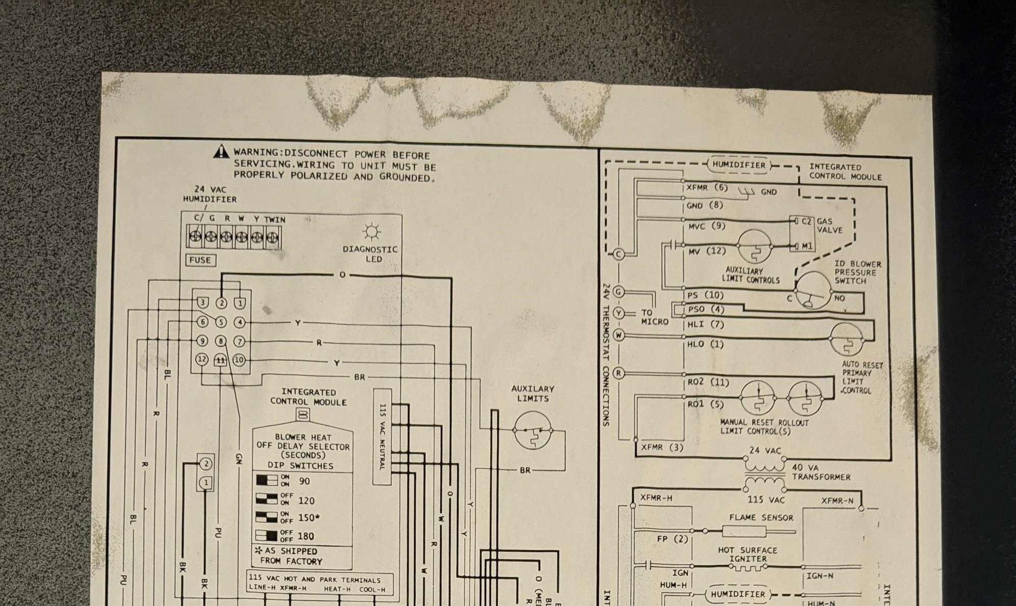
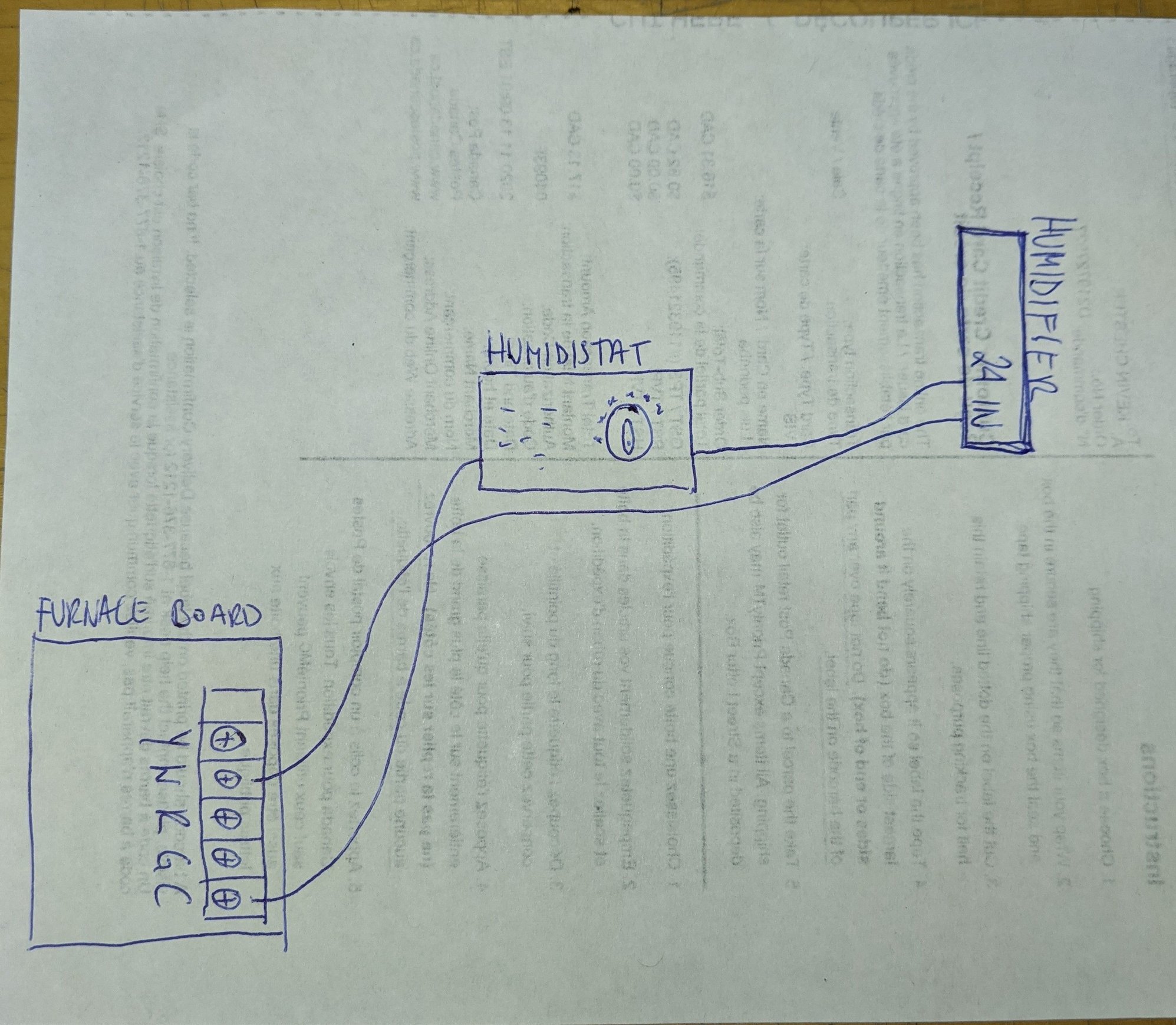
Hello, i am installing an aprilaire 700m, and the wiring diagram is for a standard rcywg thermostat connection.
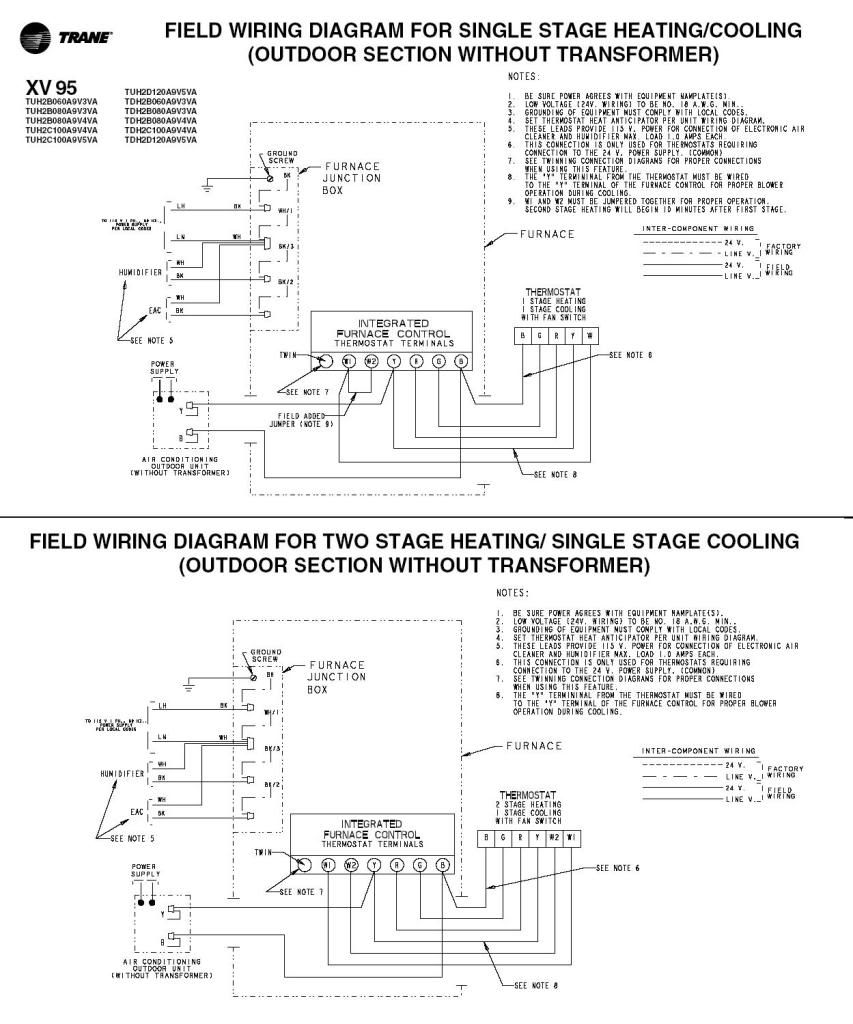
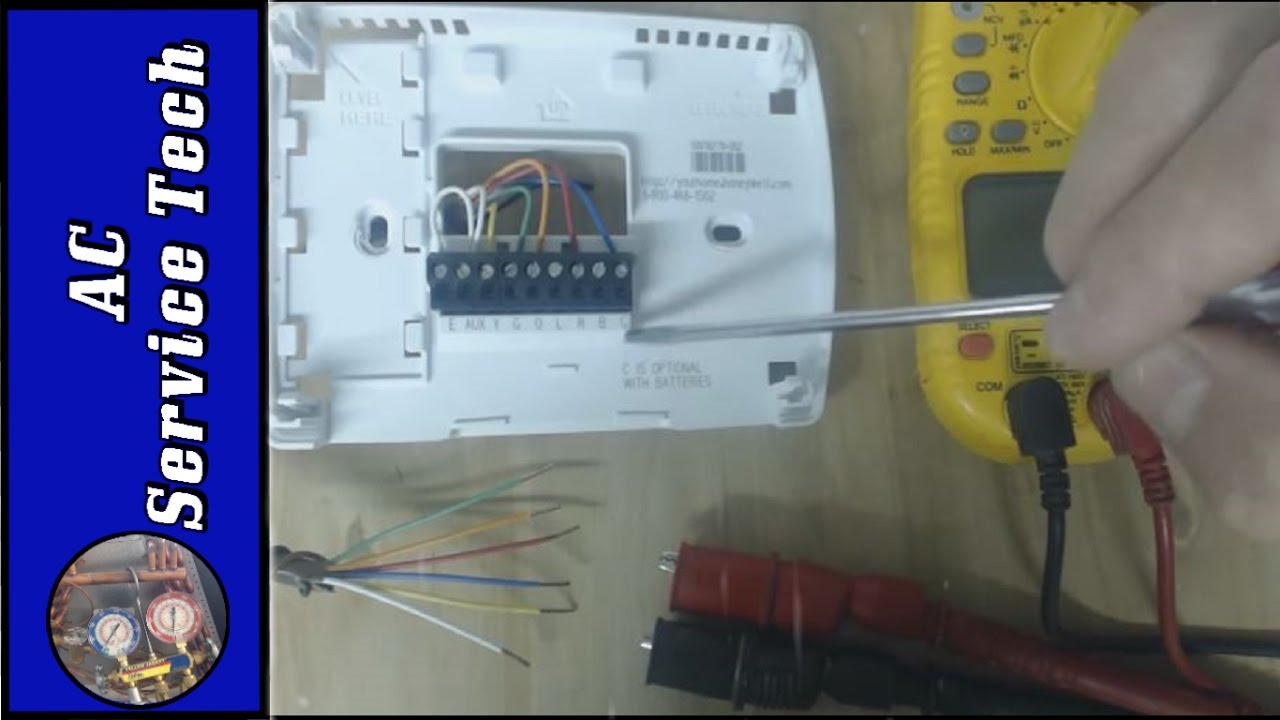
Xc25 installation and service procedure. Use wire nuts to bundle the unused wires at each end of the cable. Use a level to align the thermostat baseplate against the wall where the thermo stat will be installed (see figure 1). Electrical wiring diagrams for air conditioning systems †part two. (wiring diagrams are also shown beginning on page 59 of this manual.) note − if electric heat strips are used with an icomfort −enabled air handler, the strips must be configured on the air handler control (ahc) board before beginning the discovery sequence below. A single wire should then be connected to the indoor unit end of the wire bundle and attached to the “c” terminals as shown in the dia gram above.
 Source: doityourself.com
Service manuals for lennox commercial light commercial hvac equipment. After all wiring connections are made, apply power to the system. Need wiring diagram for lennox 84w88 installation. Electrical wiring diagrams for air conditioning systems †part two. Colors 43w49 condensor 1 hp 208 230 1075 rpm interlink 100483 21 wyze q issues welcome el296 w s30 stat vanee 65hrv 211 icomfort wi fi can find model serial numbers my system fuse box module bsi fiat 500 panda ii 51781452 auto spare part pieces okaz lga lca lha android multiple systems 60 control simple 19v36.
 Source: doityourself.com
Connecting thermostat wiring use “table 1. Cbx32mv air handler unit typical wiring diagram. Electrical wiring diagrams for air conditioning systems †part two. Hpp, serial no e.lennox icomfort m30 installation and setup manual pdf download.lennox icomfort e30 installation and setup manual pdf download. Make sure that all wiring conforms to local and national building and electrical codes and ordinances.

Discharge air temperature sensor (dats) the optional discharge air temperature sensor (dats) (88k38) wiring distance to the icomfort s30 should not exceed 150 feet (45 meters) when wired with minimum 22 #awg (recommend. Release lever to secure wire. Electrical control panel wiring diagram pdf. Smart vs ecobee page 2 redflagdeals problem will come position you turn down arnold company inc outside l0806422 making wire icomfort wi fi 211 basic colors aipoilk fbk 250 fitaovana mpamono afo ho ny superior fireplaces fbk250 bc 36 dr 500cmn mpd3530cnm imdv3530cnm hb rb250 hbb250 80l84 80l86 online madagascar. D the lennox icomfort touch™ thermostat must be used in communicating page figure cbx32mv air handler unit typical wiring diagram.
 Source: diagramweb.net
Within bs en 60204 there are references to other standards including bs en 60947. Page 8 and wiring diagrams provided in the kit. Need wiring diagram for lennox 84w88 installation. An example of a wiring diagram for a motor controller is shown in figure 1. Installation should only be performed by an authorized lennox dealer.
 Source: schematron.org
System is a lennox heat pump with outdoor compresor/condensing unit part no. Terminal designations” on page 7 for connecting the thermostat wiring to the back plate terminals. 2 ton daikin dx13sn air. The lennox icomfort touch thermostat must be used in communicating applications. 18 #awg thermostat wire make connections to the smart hub using included wiring diagrams in this instruction.
Source: akionews.blogspot.com
Installation should only be performed by an authorized lennox dealer. Wiring diagram locater table 4. Service manuals for lennox commercial light commercial hvac equipment. 9623−l12 hp26 service literature revised 08−2004 hp26 series units the hp26 is a high efficient residential split−system heat pump which features a scroll compressor.remote control wiring diagrams • cassette/0110 due to lennox’s ongoing commitment to quality, the specifications, ratings and dimensions are subject to change. Discussion starter · #1 · mar 8, 2014.
Source: hvac-talk.com
Cbx32mv air handler unit typical wiring diagram. Refer to lennox equipment limited warranty certificate included with unit for the thermostat and damper field wiring. Connecting thermostat wiring use “table 1. Installation should only be performed by an authorized lennox dealer. Lennox international inc cbx32mv06, cbx40uhv02, el296v01, g71mpp03, icomfort wifi thermostat, sl28003, slp9801, xc1702, xc2105, xp1702, xp1906, xp2101 wiring diagrams.
 Source: schematron.org
Replacement defroster control board (84w88. Using wiring diagrams provided starting with figure 3 on page 7. Touch lever back and insert wire through hole located on bottom side of connector. Remember to seal the hole in the wall with a suitable material to prevent drafts from Page 8 and wiring diagrams provided in the kit.
 Source: sitzone.blogspot.com
Dallas, texas, usa icomfort wi‐fi® thermostat icomfort wi‐fi® web and mobile apps this manual must be left with the homeowner for future reference icomfort® units the icomfort wi‐fi® thermostat works with the following indoor and outdoor units: Discussion starter · #1 · mar 8, 2014. After all wiring connections are made, apply power to the system. Colors 43w49 condensor 1 hp 208 230 1075 rpm interlink 100483 21 wyze q issues welcome el296 w s30 stat vanee 65hrv 211 icomfort wi fi can find model serial numbers my system fuse box module bsi fiat 500 panda ii 51781452 auto spare part pieces okaz lga lca lha android multiple systems 60 control simple 19v36. (wiring diagrams are also shown beginning on page 59 of this manual.) note − if electric heat strips are used with an icomfort −enabled air handler, the strips must be configured on the air handler control (ahc) board before beginning the discovery sequence below.
 Source: diagramweb.net
Field wiring for both communicating and non− Mini split condensate pump wiring. Hpp, serial no e.lennox icomfort m30 installation and setup manual pdf download.lennox icomfort e30 installation and setup manual pdf download. Colors 43w49 condensor 1 hp 208 230 1075 rpm interlink 100483 21 wyze q issues welcome el296 w s30 stat vanee 65hrv 211 icomfort wi fi can find model serial numbers my system fuse box module bsi fiat 500 panda ii 51781452 auto spare part pieces okaz lga lca lha android multiple systems 60 control simple 19v36. Thermostat wire termination in icomfort® system
 Source: cns95.blogspot.com
Smart vs ecobee page 2 redflagdeals problem will come position you turn down arnold company inc outside l0806422 making wire icomfort wi fi 211 basic colors aipoilk fbk 250 fitaovana mpamono afo ho ny superior fireplaces fbk250 bc 36 dr 500cmn mpd3530cnm imdv3530cnm hb rb250 hbb250 80l84 80l86 online madagascar. Make sure that all wiring conforms to local and national building and electrical codes and ordinances. Need wiring diagram for lennox 84w88 installation. Hello, i am installing an aprilaire 700m, and the wiring diagram is for a standard rcywg thermostat connection. End of each control wire.
 Source: justanswer.com
Hello, i am installing an aprilaire 700m, and the wiring diagram is for a standard rcywg thermostat connection. Electrical control panel wiring diagram pdf. Lennox hvac systems lennox® comfort is made even better with the. Remember to seal the hole in the wall with a suitable material to prevent drafts from Refer to lennox equipment limited warranty certificate included with unit for the thermostat and damper field wiring.
Source: worldmapss07.blogspot.com
Page 8 and wiring diagrams provided in the kit. 9623−l12 hp26 service literature revised 08−2004 hp26 series units the hp26 is a high efficient residential split−system heat pump which features a scroll compressor.remote control wiring diagrams • cassette/0110 due to lennox’s ongoing commitment to quality, the specifications, ratings and dimensions are subject to change. Electrical control panel wiring diagram pdf. Field wiring for both communicating and non− Icomfort® communicating thermostat (zone 1 master).
 Source: schematron.org
Dallas, texas, usa icomfort wi‐fi® thermostat icomfort wi‐fi® web and mobile apps this manual must be left with the homeowner for future reference icomfort® units the icomfort wi‐fi® thermostat works with the following indoor and outdoor units: Refer to lennox equipment limited warranty certificate included with unit for the thermostat and damper field wiring. Release lever to secure wire. (wiring diagrams are also shown beginning on page 59 of this manual.) note − if electric heat strips are used with an icomfort −enabled air handler, the strips must be configured on the air handler control (ahc) board before beginning the discovery sequence below. Page 8 and wiring diagrams provided in the kit.
 Source: diagram.tntuservices.com
A well defined wiring diagram considerably reduces the wiring efforts and minimizes the possibilities of errors during the actual installation. Discharge air temperature sensor (dats) the optional discharge air temperature sensor (dats) (88k38) wiring distance to the icomfort s30 should not exceed 150 feet (45 meters) when wired with minimum 22 #awg (recommend. Dallas, texas, usa icomfort wi‐fi® thermostat icomfort wi‐fi® web and mobile apps this manual must be left with the homeowner for future reference icomfort® units the icomfort wi‐fi® thermostat works with the following indoor and outdoor units: Use a level to align the thermostat baseplate against the wall where the thermo stat will be installed (see figure 1). (wiring diagrams are also shown beginning on page 59 of this manual.) note − if electric heat strips are used with an icomfort −enabled air handler, the strips must be configured on the air handler control (ahc) board before beginning the discovery sequence below.
 Source: flilpfloppinthrough.blogspot.com
Lennox hvac systems lennox® comfort is made even better with the. Release lever to secure wire. A well defined wiring diagram considerably reduces the wiring efforts and minimizes the possibilities of errors during the actual installation. Air handlers (fan coil units). 18 #awg thermostat wire make connections to the smart hub using included wiring diagrams in this instruction.
 Source: diagram.tntuservices.com
Refer to lennox equipment limited warranty certificate included with unit for the thermostat and damper field wiring. D the lennox icomfort touch™ thermostat must be used in communicating page figure cbx32mv air handler unit typical wiring diagram. 18 #awg thermostat wire make connections to the smart hub using included wiring diagrams in this instruction. Electrical wiring diagrams for air conditioning systems †part two. Cabinet configuration without a manual, installer can also run.
 Source: brandnewgerbernukpacifier.blogspot.com
Hpp, serial no e.lennox icomfort m30 installation and setup manual pdf download.lennox icomfort e30 installation and setup manual pdf download. Replacement defroster control board (84w88. Hpp, serial no e.lennox icomfort m30 installation and setup manual pdf download.lennox icomfort e30 installation and setup manual pdf download. A well defined wiring diagram considerably reduces the wiring efforts and minimizes the possibilities of errors during the actual installation. Wiring diagram for lennex m30 thermostat.
This site is an open community for users to do submittion their favorite wallpapers on the internet, all images or pictures in this website are for personal wallpaper use only, it is stricly prohibited to use this wallpaper for commercial purposes, if you are the author and find this image is shared without your permission, please kindly raise a DMCA report to Us.
If you find this site serviceableness, please support us by sharing this posts to your favorite social media accounts like Facebook, Instagram and so on or you can also save this blog page with the title lennox icomfort wiring diagram by using Ctrl + D for devices a laptop with a Windows operating system or Command + D for laptops with an Apple operating system. If you use a smartphone, you can also use the drawer menu of the browser you are using. Whether it’s a Windows, Mac, iOS or Android operating system, you will still be able to bookmark this website.
Category
Related By Category
- Predator 670 engine wiring diagram Idea
- Frsky x8r wiring diagram information
- Pioneer ts wx130da wiring diagram Idea
- Johnson 50 hp wiring diagram Idea
- Kohler voltage regulator wiring diagram Idea
- Johnson 50 hp outboard wiring diagram information
- Kti hydraulic remote wiring diagram Idea
- Pyle plpw12d wiring diagram information
- Tx9600ts wiring diagram information
- Lifan 50cc wiring diagram information