L1 l2 wiring diagram information
Home » Trending » L1 l2 wiring diagram information
Your L1 l2 wiring diagram images are ready. L1 l2 wiring diagram are a topic that is being searched for and liked by netizens now. You can Download the L1 l2 wiring diagram files here. Find and Download all free images.
If you’re looking for l1 l2 wiring diagram images information related to the l1 l2 wiring diagram interest, you have pay a visit to the ideal site. Our site frequently provides you with hints for downloading the maximum quality video and image content, please kindly surf and find more enlightening video articles and images that match your interests.
L1 L2 Wiring Diagram. New pump�s diagram suggests line on l1 (note: The three winding end connected together at the centre are is called the neutral (denoted as ‘n’). Air conditioner 230v l1 vs l2 wiring diagram. Wiring diagram book a1 15 b1 b2 16 18 b3 a2 b1 b3 15 supply voltage 16 18 l m h 2 levels b2 l1 f u 1 460 v f u 2 l2 l3 gnd h1 h3 h2 h4 f u 3 x1a f u 4 f u 5 x2a r power on optional x1 x2115 v 230 v h1 h3 h2 h4 optional connection electrostatically shielded transformer f u 6 off on m l1 l2 1 2 stop ol m start 3 start start fiber optic.
 Dimmer Switch Wiring Diagram L1 L2 Database Wiring From faceitsalon.com
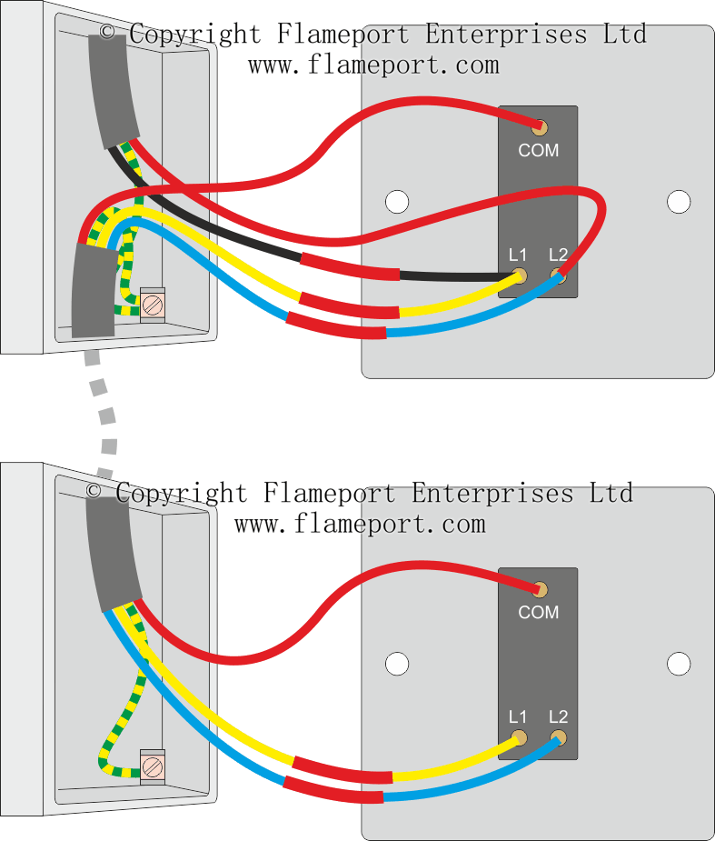
When you make use of your finger or perhaps the actual circuit with your eyes, it is easy to mistrace the circuit. It shows the components of the circuit as simplified shapes and the capability and signal links along with the devices. Light switch wiring diagram l1 l2. The yellow wire goes in the common terminal, red in the l1 terminal and blue goes in the l2 terminal. A arrangement of optical fibers l1 l2 l3 are the locations scientific diagram. When you’re wiring decorative light switches such as chrome or stainless steel etc, you’ll find that the switch will also have an l2 terminal which means it’s a two way switch.
The other ends are called the line end (denoted as ‘l1’, ‘l2’ and ‘l3’).
L1 l2 com wiring diagram wiring diagram is a simplified suitable pictorial representation of an electrical circuit. L1 and l2 indicate that the motor voltage may be. L1 l2 com wiring diagram wiring diagram is a simplified suitable pictorial representation of an electrical circuit. L1 and l2 stand for line 1 and line 2. Light switch wiring diagram l1 l2. The text neutral line confuses me).
 Source: askthetrades.co.uk
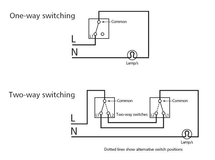
Dimmer switch wiring diagram l1 l2 from www.lightwiring.co.uk. Cable layouts l1 l2 and l3 phase conductors n neutral conductor scientific diagram. Injunction of two wires is generally indicated by black dot at the junction of 2 lines. L1 and l2 motor wiring the l symbol designation refers to the line, or the incoming circuit wires that provide the power for the motor. Wiring a one way switch the other terminal is marked as l1 and is the output to the light fixture.
 Source: tonetastic.info
The voltage between two lines (for example ‘l1’ and ‘l2’) is called the line to line (or phase to phase) voltage. What does l1 and l2 mean on a light switch? Wiring a one way switch the other terminal is marked as l1 and is the output to the light fixture. The 3 phases l1 l2 and l3 would be coloured brown black and grey. Cable layouts l1 l2 and l3 phase conductors n neutral conductor scientific diagram.
 Source: faceitsalon.com
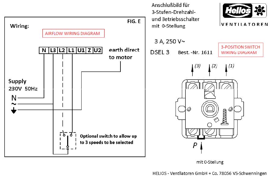
L1 and l2, for example, imply that the motor voltage may be 240 volts. T1 t2 t3 t4 t5 t6 t7 t8 t9 t10 t11 t12 t13 t lead wires for motors and fans these are the terminal leads of the motor or fan. Pre printed cable markers wic1 l1 l2 l3 n earth 561 01300 ermanntyton. I�m wiring a new pump (usq1072) for 115v operation the old pump�s diagram (115v) has line on l2. It shows the components of the circuit as simplified shapes, and the capability and signal links along with the devices.
 Source: wiringdiagram.2bitboer.com
Connect now shop homex recommended products L1 l2 com wiring diagram wiring diagram is a simplified suitable pictorial representation of an electrical circuit. L1 and l2, for example, imply that the motor voltage may be 240 volts. The text neutral line confuses me). They will be marked so you can tell which is.
 Source: tonetastic.info
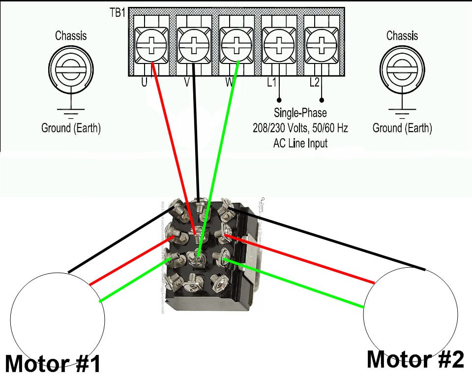
They will be marked so you can tell which is. L1 and l2, for example, imply that the motor voltage may be 240 volts. Wiring diagrams for l1 and l2 motors the l symbol denotes the line, or the incoming circuit wires that supply electricity to the motor. It shows the components of the circuit as simplified shapes, and the capability and signal links along with the devices. The l symbol designation refers to the line, or the incoming circuit wires that provide the power for the motor.
 Source: diagramweb.net
Wiring a one way switch the other terminal is marked as l1 and is the output to the light fixture. It shows the components of the circuit as simplified shapes, and the capability and signal links along with the devices. L1 and l2, for example, imply that the motor voltage may be 240 volts. A wiring diagram usually gives recommendation practically the relative approach and understanding of. L1 and l2 motor wiring.
 Source: yazminahmed.blogspot.com
L1 l2 com wiring diagram wiring diagram is a simplified suitable pictorial representation of an electrical circuit. Search for motorguide trolling motor wiring diagram here and subscribe to this site motorguide trolling motor wiring diagram read more! The three winding end connected together at the centre are is called the neutral (denoted as ‘n’). The l symbol designation refers to the line, or the incoming circuit wires that provide the power for the motor. Cable layouts l1 l2 and l3 phase conductors n neutral conductor scientific diagram.
 Source: tonetastic.info
There’ll be principal lines that are represented by l1, l2, l3, and so on. Light switch wiring diagram l1 l2. There’ll be principal lines that are represented by l1, l2, l3, and so on. The other ends are called the line end (denoted as ‘l1’, ‘l2’ and ‘l3’). L1 l2 com wiring diagram wiring diagram is a simplified suitable pictorial representation of an electrical circuit.
 Source: tonetastic.info
When you make use of your finger or perhaps the actual circuit with your eyes, it is easy to mistrace the circuit. Diagram dd9 1ø wiring diagrams ln e l1 l2 l3 s/c z2 u2 z1 u1 cap. I understand that it really doesn�t make a difference, as long as my line (in) is the side that is switched (which is is), so the motor. The text neutral line confuses me). When you make use of your finger or perhaps the actual circuit with your eyes, it is easy to mistrace the circuit.
 Source: wiringdiagrams-az.blogspot.com
L1 and l2, for example, imply that the motor voltage may be 240 volts. Light switch wiring diagram l1 l2. Wiring a one way switch the other terminal is marked as l1 and is the output to the light fixture. L1 l2 com wiring diagram wiring diagram is a simplified suitable pictorial representation of an electrical circuit. T1 t2 t3 t4 t5 t6 t7 t8 t9 t10 t11 t12 t13 t lead wires for motors and fans these are the terminal leads of the motor or fan.
 Source: caffreyknives.net
L1 l2 com wiring diagram wiring diagram is a simplified suitable pictorial representation of an electrical circuit. Print the wiring diagram off plus use highlighters to trace the signal. Light switch l1 l2 vs l3 intermediate wiring types of lighting switches diynot forums circuits mapping old to new smatrul tuya smart wifi labels an how excel touch eu sonoff t1 uk user guide ewelink wall top 19 meaning mới nhất 2022 2 us công tắc cảm ứng thông minh không added a photo màn hình ứng 4 nút 4ch r3 gang wi fi diy master. L1 l2 com wiring diagram wiring diagram is a simplified suitable pictorial representation of an electrical circuit. Our virtual experts can diagnose your issue (for free!) and resolve simple problems.
 Source: tonetastic.info
Our virtual experts can diagnose your issue (for free!) and resolve simple problems. L1 and l2 indicate that the motor voltage may be 240 volts. The text neutral line confuses me). There’ll be principal lines that are represented by l1, l2, l3, and so on. The t symbol designation refers to the terminal or termination, which in this case is a wire lead that.
 Source: wiringdiagramall.blogspot.com
Wiring diagram book a1 15 b1 b2 16 18 b3 a2 b1 b3 15 supply voltage 16 18 l m h 2 levels b2 l1 f u 1 460 v f u 2 l2 l3 gnd h1 h3 h2 h4 f u 3 x1a f u 4 f u 5 x2a r power on optional x1 x2115 v 230 v h1 h3 h2 h4 optional connection electrostatically shielded transformer f u 6 off on m l1 l2 1 2 stop ol m start 3 start start fiber optic. L1 and l2 motor wiring the l symbol designation refers to the line, or the incoming circuit wires that provide the power for the motor. The three winding end connected together at the centre are is called the neutral (denoted as ‘n’). The l1 is the switched live going out to the lightthey will be marked so you can tell which is which. A wiring diagram usually gives recommendation practically the relative approach and understanding of.
 Source: faceitsalon.com
Light switch wiring diagram l1 l2. L1 and l2 stand for line 1 and line 2. They will be marked so you can tell which is. L1 and l2 motor wiring. It shows the components of the circuit as simplified shapes, and the capability and signal links along with the devices.
 Source: tonetastic.info
Connect now shop homex recommended products Print the wiring diagram off plus use highlighters to trace the signal. L1 and l2, for example, imply that the motor voltage may be 240 volts. They will be marked so you can tell which is. Dimmer switch wiring diagram l1 l2 from www.lightwiring.co.uk.
 Source: tonetastic.info
Wiring a one way switch the other terminal is marked as l1 and is the output to the light fixture. However, only one of these lines (l1 in this case) will have power attached to it at any given time. L1 and l2, for example, imply that the motor voltage may be 240 volts. It shows the components of the circuit as simplified shapes, and the capability and signal links along with the devices. L1 and l2 indicate that the motor voltage may be 240 volts.
Source: drivenheisenberg.blogspot.com
L1 and l2 indicate that the motor voltage may be 240 volts. Injunction of two wires is generally indicated by black dot at the junction of 2 lines. L1 and l2 stand for line 1 and line 2. L1 l2 com wiring diagram wiring diagram is a simplified suitable pictorial representation of an electrical circuit. The yellow wire goes in the common terminal, red in the l1 terminal and blue goes in the l2 terminal.
 Source: yazminahmed.blogspot.com
Josephine ⭐ answeregy expert l1 l2 com wiring diagram | autocardesign Intermediate light switch wiring l1 l2 l3 l4 vs diynot forums two way switched lighting circuits 1 types of switches bathroom hall mapping old to new fix community forum what do and com mean on a quora sportyfie the letters l behind that you don t know each represent. The three winding end connected together at the centre are is called the neutral (denoted as ‘n’). I understand that it really doesn�t make a difference, as long as my line (in) is the side that is switched (which is is), so the motor. Wiring diagrams for l1 and l2 motors the l symbol denotes the line, or the incoming circuit wires that supply electricity to the motor.
This site is an open community for users to share their favorite wallpapers on the internet, all images or pictures in this website are for personal wallpaper use only, it is stricly prohibited to use this wallpaper for commercial purposes, if you are the author and find this image is shared without your permission, please kindly raise a DMCA report to Us.
If you find this site beneficial, please support us by sharing this posts to your own social media accounts like Facebook, Instagram and so on or you can also bookmark this blog page with the title l1 l2 wiring diagram by using Ctrl + D for devices a laptop with a Windows operating system or Command + D for laptops with an Apple operating system. If you use a smartphone, you can also use the drawer menu of the browser you are using. Whether it’s a Windows, Mac, iOS or Android operating system, you will still be able to bookmark this website.
Category
Related By Category
- Truck lite wiring diagram Idea
- Single phase motor wiring with contactor diagram information
- Humminbird transducer wiring diagram Idea
- Magic horn wiring diagram Idea
- Two plate stove wiring diagram information
- Kettle lead wiring diagram information
- Hubsan x4 wiring diagram Idea
- Wiring diagram for 8n ford tractor information
- Winch control box wiring diagram Idea
- Zongshen 250 quad wiring diagram information