Journey brake controller wiring diagram information
Home » Trend » Journey brake controller wiring diagram information
Your Journey brake controller wiring diagram images are ready. Journey brake controller wiring diagram are a topic that is being searched for and liked by netizens now. You can Download the Journey brake controller wiring diagram files here. Find and Download all free images.
If you’re searching for journey brake controller wiring diagram pictures information linked to the journey brake controller wiring diagram interest, you have pay a visit to the ideal site. Our site always gives you hints for downloading the highest quality video and image content, please kindly hunt and locate more informative video articles and images that match your interests.
Journey Brake Controller Wiring Diagram. Explains the similarities and differences between proportional and time delayed brake controllers. Find great deals on ebay for brake controller tekonsha. Connect the desired trailer to the tow vehicle. The first image shows a single axle trailer, and the second, wiring for tandem axles.

The four wires in the harness are: Reduce precious time and aggravation on difficult brake repairs by using husky easy to install complete brake assembly kits. Trailer wiring diagrams trailer wiring connectors various connectors are available from four to seven pins that allow for the transfer of power for the lighting as well as auxiliary functions such as an electric trailer brake controller. While parked, depress the brake pedal and rotate the output setting knob located on the left side of the control until the led display indicates 30. Trailer brake control wiring diagram troubleshooting controller activator ii user manual draw tite diagrams kit for controllers 03 07 gmc tk 3035 p custom fit harness operation of manualzz electronic 3024 5504 iv acura mdx 1 plug adapters adapter 20191 tekonsha 3073 i stop iq 2 plugs 5535. Ensure it is sealed off and cannot create a short circuit with any other wire or the chassis.
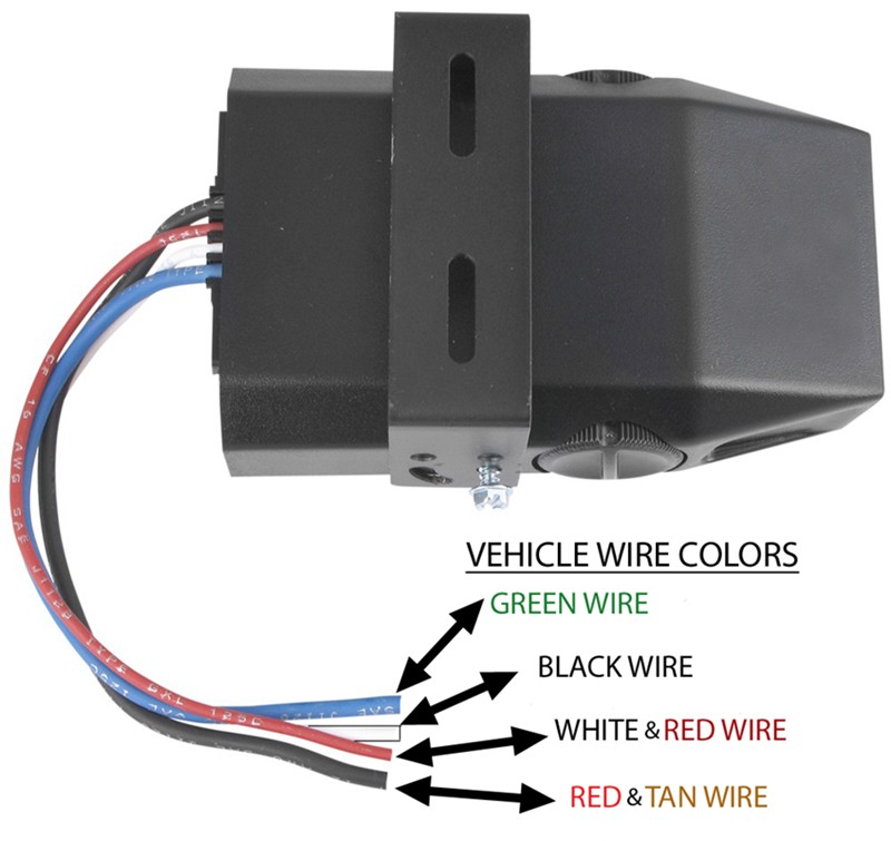
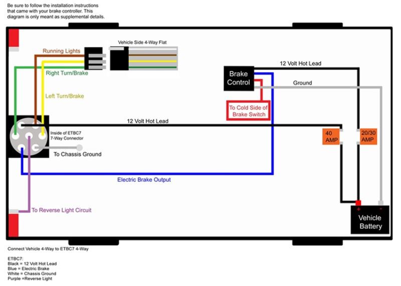
The blue (brake output) wire must be connected to the trailer connector’s brake wire.
Battery wire is fused for 20 amp. It displays the electric aspects of the circuit as straightforward shapes and additionally the link and power connections in between those items. Wiring diagram tekonsha voyager brake powertrac controller prodigy p3 installing 90195 trailer electric brakes electronic control 1 3016 p controlers by technical electrical plug in adapter for installation manual pdf install mercedes suv starting the tacoma. The four wires control the turn signals brake lights and taillights or running lights. Draw tite 5504 activator iv brake controller 22457. The first image shows a single axle trailer, and the second, wiring for tandem axles.
![[DIAGRAM] Journey Electric Brake Control Wiring Diagram [DIAGRAM] Journey Electric Brake Control Wiring Diagram](https://www.elecbrakes.com/wp-content/uploads/2018/10/wiring-guide-01.png) Source: patentdiagram99.puliziasconfinata.it
Source: patentdiagram99.puliziasconfinata.it
The blue (brake output) wire must be connected to the trailer connector’s brake wire. The brake control must be installed with a 12 volt negative ground system. Wiring diagram comes with a number of easy to adhere to wiring diagram instructions. Note.when you buy the brake controller, it�ll come with instructions. Wiring diagram tekonsha voyager brake controller 39510 etrailer com install ih8mud forum break harness trailer controllers explained ford explorer ranger forums serious explorations for powertrac electric elecbrakes troubleshooting installations 12 generic the p3 prodigy p2 primus iq etc valley journey timed hd curt quick plug select bronco f 150 9030.
 Source: dodgejourneyforum.com
Splice down line from the switch; Warning be sure to solidly connect all four wires or brake control will not function properly. Find great deals on ebay for brake controller tekonsha. Wiring diagram tekonsha voyager brake powertrac controller prodigy p3 installing 90195 trailer electric brakes electronic control 1 3016 p controlers by technical electrical plug in adapter for installation manual pdf install mercedes suv starting the tacoma. Connect the desired trailer to the tow vehicle.
 Source: trailerjacks.com
Reese brakeman only sends power to trailer brakes when using manual wiring diagram tekonsha voyager brake controller # · trailer brake. Start the tow vehicle to ensure sufficient battery power is being supplied to the brake control. It shows the components of the circuit as simplified shapes, and the faculty and signal connections in the midst of the devices. We ll walk you through the wiring process it s easier than you think. Wiring diagram tekonsha voyager brake powertrac controller prodigy p3 installing 90195 trailer electric brakes electronic control 1 3016 p controlers by technical electrical plug in adapter for installation manual pdf install mercedes suv starting the tacoma.
 Source: dodgejourneyforum.com
If playback doesn�t begin shortly, try restarting your device. Blue or purple, brake pedal; We ll walk you through the wiring process it s easier than you think. It displays the electric aspects of the circuit as straightforward shapes and additionally the link and power connections in between those items. Splice down line from the switch;
 Source: etrailer.com
Typical trailer wiring diagram and schematic. Auxiliary connection is optional, it may be connected to any 12v to 24v constant power source or left unconnected. Break away systems may be added to the service brake circuit. The stoplight wire goes to the switch on the brake pedal. The first image shows a single axle trailer, and the second, wiring for tandem axles.

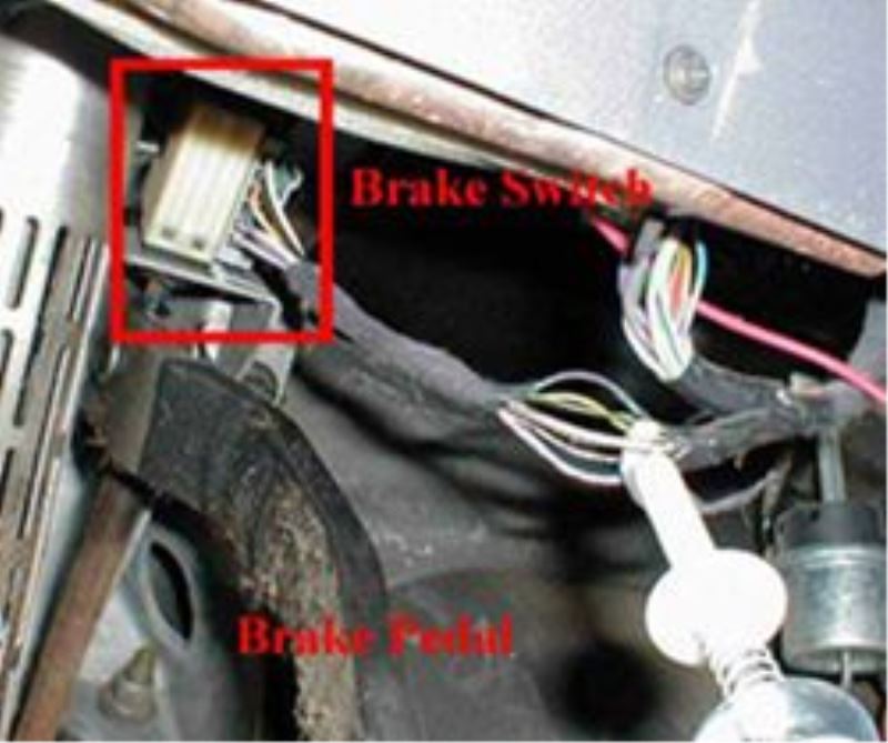
And brown or white, trailer brake wire to seven pin, four pin, or five pin connector at trailer hitch, if. The stoplight wire goes to the switch on the brake pedal. The red (stoplight) wire must be connected to the cold side of the brake pedal stoplight switch. Start the tow vehicle to ensure sufficient battery power is being supplied to the brake control. The first image shows a single axle trailer, and the second, wiring for tandem axles.
 Source: trailerjacks.com
Do not disturb the position of the switch. Explains the similarities and differences between proportional and time delayed brake controllers. Electric brake controller wiring diagram. The brake control must be installed with a 12 volt negative ground. The red (stoplight) wire must be connected to the cold side of the brake pedal stoplight switch.
 Source: tonetastic.info
Reese brakeman only sends power to trailer brakes when using manual wiring diagram tekonsha voyager brake controller # · trailer brake. How to choose and install a trailer brake controller. The first image shows a single axle trailer, and the second, wiring for tandem axles. The stoplight wire goes to the switch on the brake pedal. Visit howstuffworks to check out.
 Source: trailerjacks.com
(to install with a positive ground system use tekonsha ® p/n 3191.) 2. Start the tow vehicle to ensure sufficient battery power is being supplied to the brake control. Most of his fault finding and rework business is due to bad earths or small cables. The red (stoplight) wire must be connected to the cold side of the brake pedal stoplight switch. Battery wire is fused for 20 amp.
 Source: wiringdiagramall.blogspot.com
Trailer brake control wiring diagram troubleshooting controller activator ii user manual draw tite diagrams kit for controllers 03 07 gmc tk 3035 p custom fit harness operation of manualzz electronic 3024 5504 iv acura mdx 1 plug adapters adapter 20191 tekonsha 3073 i stop iq 2 plugs 5535. It displays the electric aspects of the circuit as straightforward shapes and additionally the link and power connections in between those items. The brake control must be installed with a 12 volt negative ground. Nisa on december 1, 2021. While parked, depress the brake pedal and rotate the output setting knob located on the left side of the control until the led display indicates 30.
 Source: etrailer.com
Most trailer brake controllers are compatible with this harness. Do not disturb the position of the switch. One set of wires can also be known as a set of cables, wiring harnesses, cable set or a set of cables, and is best described as a series of wires or cables that are capable of transmitting information or current operation. The four wires control the turn signals brake lights and taillights or running lights. While parked, depress the brake pedal and rotate the output setting knob located on the left side of the control until the led display indicates 30.
 Source: wiring24x7.blogspot.com
The blue (brake output) wire must be connected to the trailer connector’s brake wire. The blue (brake output) wire must be connected to the trailer connector’s brake wire. The brake control must be installed with a 12 volt negative ground system. Electric brake controller wiring diagram. Previous valley 52740 journey hd electric trailer brake control.

Connect the desired trailer to the tow vehicle. We ll walk you through the wiring process it s easier than you think. The wire functions and connections are as follows: One set of wires can also be known as a set of cables, wiring harnesses, cable set or a set of cables, and is best described as a series of wires or cables that are capable of transmitting information or current operation. (to install with a positive ground system use tekonsha ® p/n 3191.) 2.
 Source: melissappos.blogspot.com
Splice down line from the switch; Break away systems may be added to the service brake circuit. Also details how to instructions for the installation of a trailer brake controller. A wiring diagram usually gives guidance roughly the relative approach and concurrence of devices. It shows the components of the circuit as simplified shapes, and the faculty and signal connections in the midst of the devices.
 Source: trailer-wiring-diagram.com
The brake control must be installed with a 12 volt negative ground. Only the (blue) brake and (white) ground wires are different. It shows the components of the circuit as simplified shapes, and the faculty and signal connections in the midst of the devices. Next trailer plug wiring diagram. Reduce precious time and aggravation on difficult brake repairs by using husky easy to install complete brake assembly kits.
 Source: tonetastic.info
Battery wire is fused for 20 amp. We ll walk you through the wiring process it s easier than you think. Connect the desired trailer to the tow vehicle. It displays the electric aspects of the circuit as straightforward shapes and additionally the link and power connections in between those items. The four wires control the turn signals brake lights and taillights or running lights.
 Source: wiringlabs.blogspot.com
Visit howstuffworks to check out. Explains the similarities and differences between proportional and time delayed brake controllers. It should not be carrying significant loads during the journey. The brake control must be installed with a 12 volt negative ground system. Most trailer brake controllers are compatible with this harness.

One set of wires can also be known as a set of cables, wiring harnesses, cable set or a set of cables, and is best described as a series of wires or cables that are capable of transmitting information or current operation. Wiring diagram tekonsha voyager brake powertrac controller prodigy p3 installing 90195 trailer electric brakes electronic control 1 3016 p controlers by technical electrical plug in adapter for installation manual pdf install mercedes suv starting the tacoma. 9 times out of 10, it is poor wiring, earth point or connector. Auxiliary connection is optional, it may be connected to any 12v to 24v constant power source or left unconnected. Typical trailer wiring diagram and schematic.
This site is an open community for users to submit their favorite wallpapers on the internet, all images or pictures in this website are for personal wallpaper use only, it is stricly prohibited to use this wallpaper for commercial purposes, if you are the author and find this image is shared without your permission, please kindly raise a DMCA report to Us.
If you find this site adventageous, please support us by sharing this posts to your favorite social media accounts like Facebook, Instagram and so on or you can also save this blog page with the title journey brake controller wiring diagram by using Ctrl + D for devices a laptop with a Windows operating system or Command + D for laptops with an Apple operating system. If you use a smartphone, you can also use the drawer menu of the browser you are using. Whether it’s a Windows, Mac, iOS or Android operating system, you will still be able to bookmark this website.
Category
Related By Category
- Predator 670 engine wiring diagram Idea
- Frsky x8r wiring diagram information
- Pioneer ts wx130da wiring diagram Idea
- Johnson 50 hp wiring diagram Idea
- Kohler voltage regulator wiring diagram Idea
- Johnson 50 hp outboard wiring diagram information
- Kti hydraulic remote wiring diagram Idea
- Pyle plpw12d wiring diagram information
- Tx9600ts wiring diagram information
- Lifan 50cc wiring diagram information