Johnson controls wiring diagram Idea
Home » Trending » Johnson controls wiring diagram Idea
Your Johnson controls wiring diagram images are ready. Johnson controls wiring diagram are a topic that is being searched for and liked by netizens today. You can Get the Johnson controls wiring diagram files here. Get all free vectors.
If you’re searching for johnson controls wiring diagram images information linked to the johnson controls wiring diagram keyword, you have come to the right blog. Our website always gives you suggestions for seeing the maximum quality video and image content, please kindly surf and locate more informative video articles and images that fit your interests.
Johnson Controls Wiring Diagram. Glaswifi wireless thermostat user manual guide johnson controls t6000 series installation instructions manualzz types a19bac a28aa single and two stage e thermostats for farm general purpose applications a421 electronic temperature with cycle timer standard. Ensure that the flame sensor wire and the high However, variations can exist, such as between remote control and tiller models. The terminal is constructed to allow installation with standard metal hanging.
 Johnson Controls Thermostat Wiring Diagram Most From tonetastic.info
Johnson controls thermostat wiring diagram. This sheet numbering is divided into ranges, reflecting the type of device or The most common elements are capacitor, resistorbattery. Johnson controls ddc for bacnet, or n2 etc. That core competency is at the heart of johnson controls. Ensure that the flame sensor wire and the high
There are also other elements such as ground, switch, motor, and inductor.
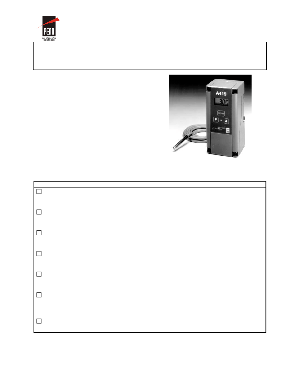
Everything depends on circuit that is being assembled. Table 1 when wiring the a419 control to your equipment. Replacement control contact the nearest johnson controls representative. By margaret byrd | july 11, 2018. Please verify your wiring before doing any work. • use wire no larger than 16 awg when connecting to the upper sensor terminal block (tb3).
 Source: forums.iboats.com
The high voltage spark transformer cable must not be in continuous contact with a metal surface. The most common elements are capacitor, resistorbattery. Table 1 when wiring the a419 control to your equipment. Blue wire used for neutral. By admin december 4 2017.
 Source: tonetastic.info
(mm) a421 control with cycle timer the a421 control with cycle timer is a. Temperature is arguably the most important component in a building s environment. Everything depends on circuit that is being assembled. Johnson controls ddc for bacnet, or n2 etc. By margaret byrd | july 11, 2018.
 Source: schematron.org
This type of diagram shows the physical relation of all devices in the system the conductor terminations between these devices and are commonly used in motor control installations. Johnson controls will not be responsible for damage/problems Occasionally, the wires will cross. Johnson controls ddc for bacnet, or n2 etc. There are also other elements such as ground, switch, motor, and inductor.
 Source: forums.iboats.com
The stop screw must be loosened and moved to the stop setting desired. Turn off all power to the equipment. • use wire no larger than 12 awg when connecting to the two lower terminal blocks (tb1 and tb2). (some wires may have additional specialized functions) Johnson controls will not be responsible for damage/problems
 Source: sitzone.blogspot.com
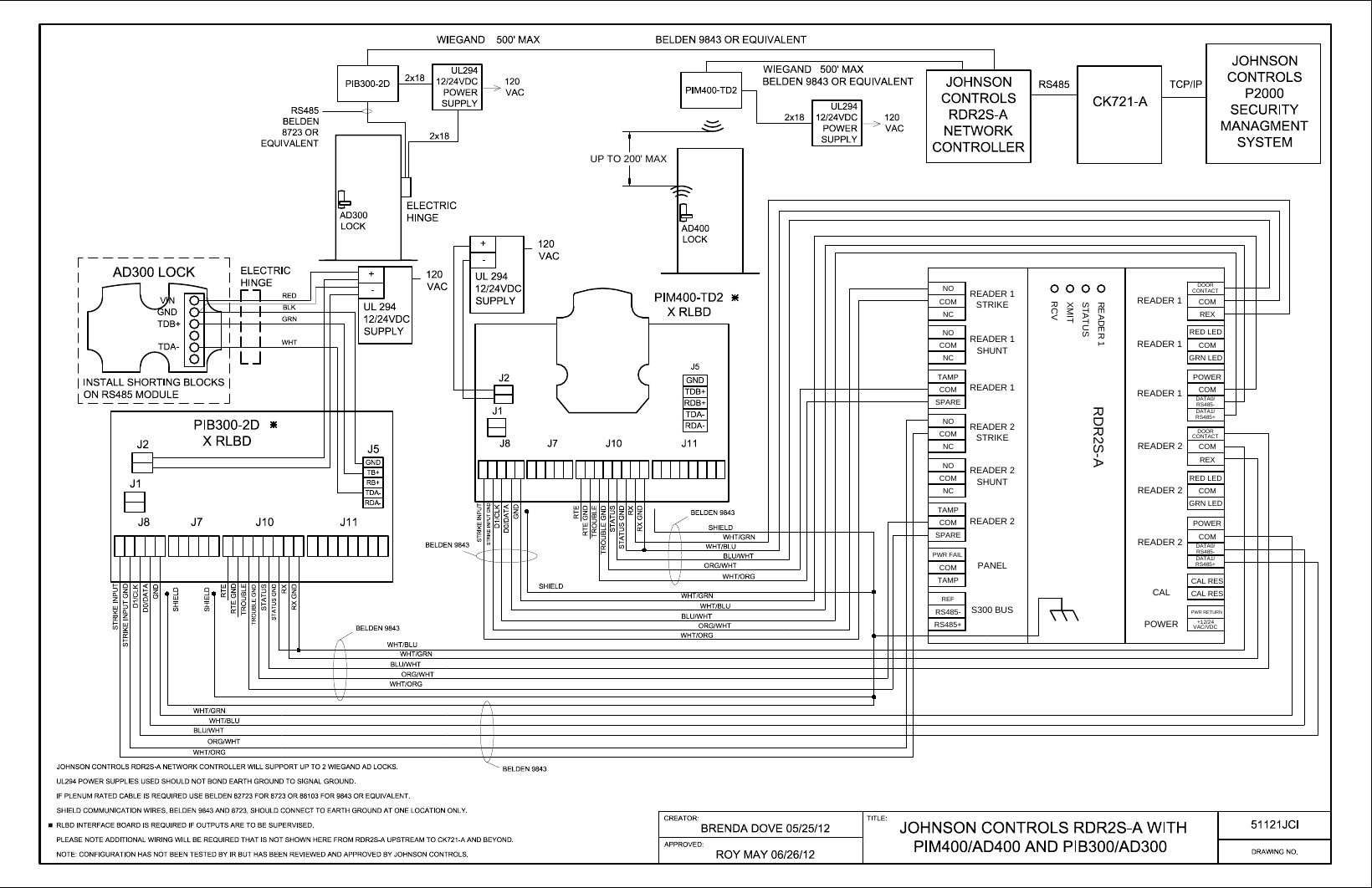
Red wire used for ac control. However, variations can exist, such as between remote control and tiller models. The stop screw must be loosened and moved to the stop setting desired. Johnson controls ddc for bacnet, or n2 etc. Schlage electronics ad300 ad400 wiring a421 series electronic temperature johnson controls a419 standard c t6000 em 3000 quick ad tec3000 on off or floating fan how to wire p470 pressure.
 Source: pinterest.com
Temperature is arguably the most important component in a building s environment. You can go to the johnson controls website and find this along with. Ensure that the flame sensor wire and the high The most common elements are capacitor, resistorbattery. There are also other elements such as ground, switch, motor, and inductor.
 Source: pinterest.com
A421abt control with type 1 (nema), ip20 enclosure; A421aet control with type 4x (nema), ip66 enclosure; Pcv1615/1626/1628/1630 controller wiring terminations and physical features table 1. 4 johnson controls general a this drawing is based on iec symbols b all sources of supply shown on this diagram to be taken from one main isolator, not shown or supplied by york. (some wires may have additional specialized functions)
 Source: usermanual.wiki
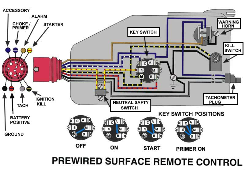
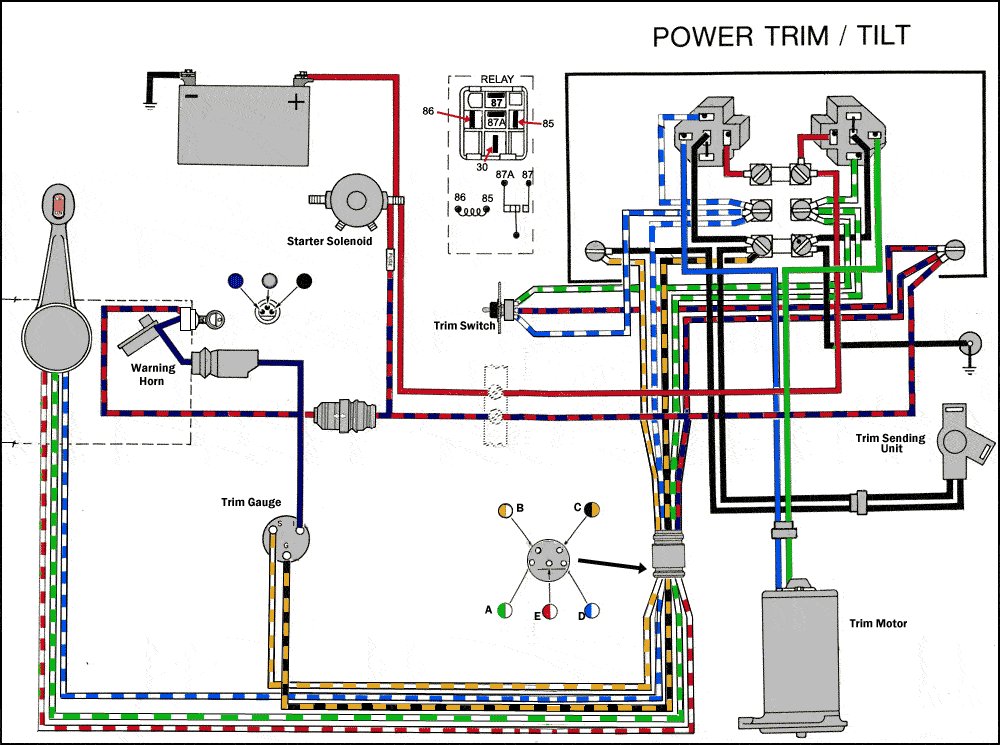
According to earlier, the lines at a johnson outboard wiring diagram pdf represents wires. When mounting field installed components, do not jumper out or rewire any factory wiring without written approval from johnson controls. (mm) a421 control with cycle timer the a421 control with cycle timer is a. So, 16/2 would be 16 gauge wire with two wires. If you have questions or request assistance, please contact us at psotechsupport@jci.com.
 Source: schematron.org
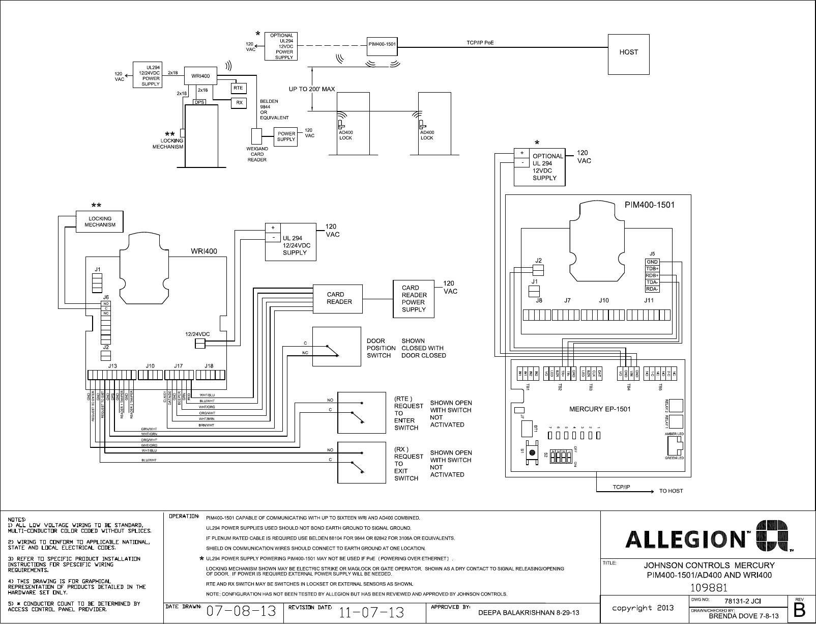
• a99 temperature sensors are not polarity • a99 temperature sensors are not polarity 4 johnson controls general a this drawing is based on iec symbols b all sources of supply shown on this diagram to be taken from one main isolator, not shown or supplied by york. Blue wire used for neutral. This type of diagram shows the physical relation of all devices in the system the conductor terminations between these devices and are commonly used in motor control installations.
 Source: usermanual.wiki
This sheet numbering is divided into ranges, reflecting the type of device or This should be the only wire attached to the ths terminal. However, variations can exist, such as between remote control and tiller models. Schlage electronics ad300 ad400 wiring a421 series electronic temperature johnson controls a419 standard c t6000 em 3000 quick ad tec3000 on off or floating fan how to wire p470 pressure. Replacement control contact the nearest johnson controls representative.
 Source: faceitsalon.com
The first number is the wire guage and the second the number of conductors. Dat by le0 mm/dd/yyyy submitted for approval ict g e n d #. Wiring diagrams description johnson controls series 5 j**ze/xn models series units are convertible single package high efficiency rooftops with a common roof curb for the 3, 4, 5, and 6 ton sizes. Occasionally, the wires will cross. The most common elements are capacitor, resistorbattery.
 Source: diagramweb.net
A421aet control with type 4x (nema), ip66 enclosure; Remove the thermostat front plate. The most common elements are capacitor, resistorbattery. This should be the only wire attached to the ths terminal. Table 1 when wiring the a419 control to your equipment.
 Source: hestiahelper.blogspot.com
The common heavier appliance cords are usually 16/2 w/ground and the ground is the third wire, but not considered a conductor. Types a19bac a28aa single and two stage e thermostats for farm general purpose applications. Johnson controls wiring diagram vfd wiring diagram showing power in power out and control device download scientific diagram By admin december 4 2017. Pcv1615/1626/1628/1630 controller wiring terminations and physical features table 1.
Source: kovodym.blogspot.com
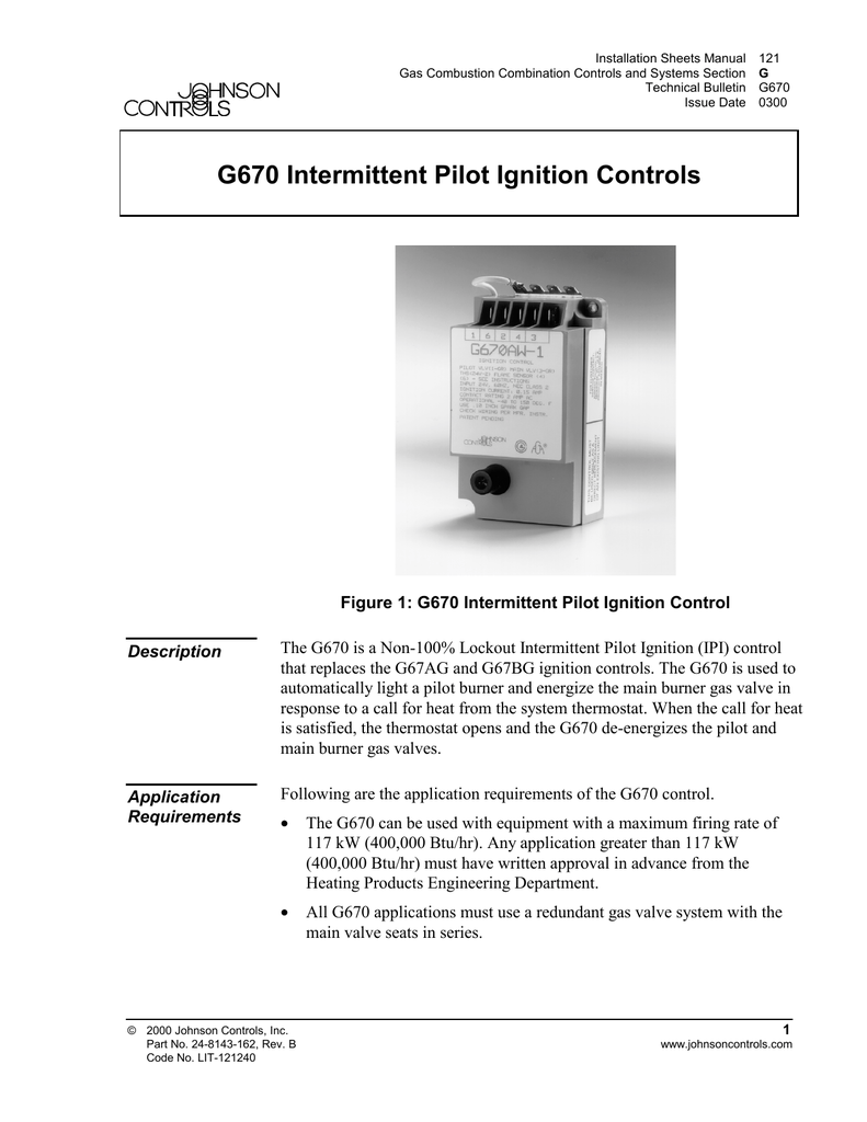
These diagrams show the wiring for particular modules or cards or detector bases which can be used with the 4100es (as4428.1) or 4100esi (as7240.2) simplex fire alarm systems. Pcv1615/1626/1628/1630 controller wiring terminations and physical features table 1. Building automation and controls product cross reference tool. Ensure that the flame sensor wire and the high voltage spark transformer cable are separated from Push any excess wiring back into the wall.
 Source: tonetastic.info
The most common elements are capacitor, resistorbattery. Ensure that the flame sensor wire and the high voltage spark transformer cable are separated from The first number is the wire guage and the second the number of conductors. Turn off all power to the equipment. (mm) a421 control with cycle timer the a421 control with cycle timer is a.
Source: askmehelpdesk.com
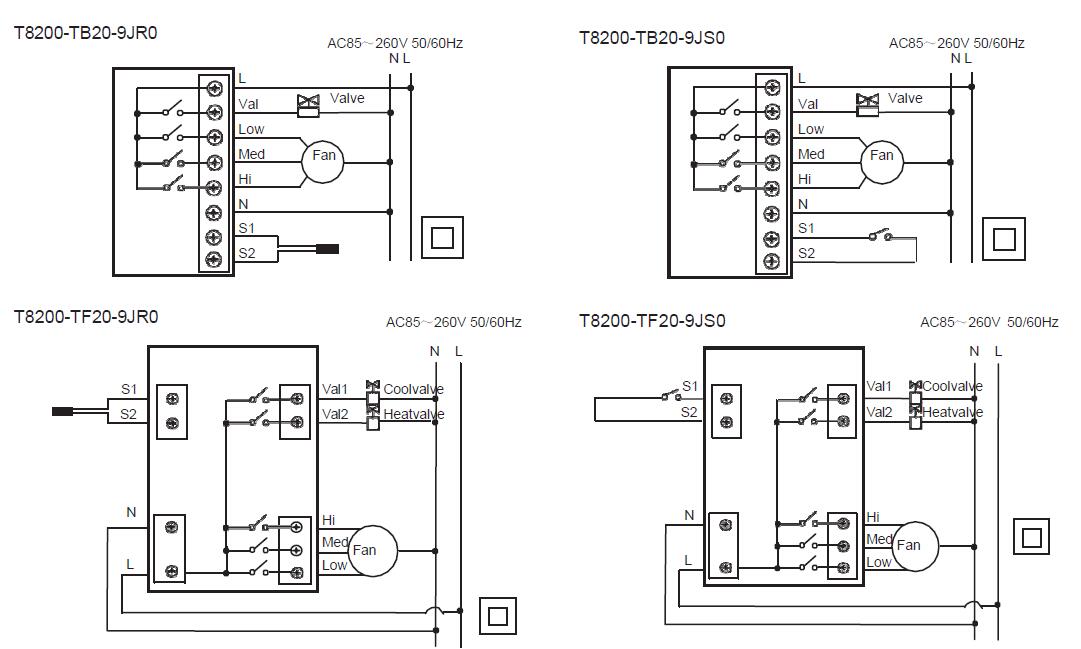
The most common elements are capacitor, resistorbattery. When mounting field installed components, do not jumper out or rewire any factory wiring without written approval from johnson controls. C green and yellow wire is used for earth. Wire sideview of plug figure 2. Johnson controls wiring diagram vfd wiring diagram showing power in power out and control device download scientific diagram
 Source: sitzone.blogspot.com
If you have questions or request assistance, please contact us at psotechsupport@jci.com. Occasionally, the wires will cross. A421aet control with type 4x (nema), ip66 enclosure; Ensure that the flame sensor wire and the high Dat by le0 mm/dd/yyyy submitted for approval ict g e n d #.
 Source: wiringall.com
This sheet numbering is divided into ranges, reflecting the type of device or Johnson controls ducted systems 11 thermostat wiring 1. Apac single point of contact: Replacement control contact the nearest johnson controls representative. Johnson controls ddc for bacnet, or n2 etc.
This site is an open community for users to do sharing their favorite wallpapers on the internet, all images or pictures in this website are for personal wallpaper use only, it is stricly prohibited to use this wallpaper for commercial purposes, if you are the author and find this image is shared without your permission, please kindly raise a DMCA report to Us.
If you find this site helpful, please support us by sharing this posts to your own social media accounts like Facebook, Instagram and so on or you can also save this blog page with the title johnson controls wiring diagram by using Ctrl + D for devices a laptop with a Windows operating system or Command + D for laptops with an Apple operating system. If you use a smartphone, you can also use the drawer menu of the browser you are using. Whether it’s a Windows, Mac, iOS or Android operating system, you will still be able to bookmark this website.
Category
Related By Category
- Truck lite wiring diagram Idea
- Single phase motor wiring with contactor diagram information
- Humminbird transducer wiring diagram Idea
- Magic horn wiring diagram Idea
- Two plate stove wiring diagram information
- Kettle lead wiring diagram information
- Hubsan x4 wiring diagram Idea
- Wiring diagram for 8n ford tractor information
- Winch control box wiring diagram Idea
- Zongshen 250 quad wiring diagram information