Jandy aqualink wiring diagram Idea
Home » Trending » Jandy aqualink wiring diagram Idea
Your Jandy aqualink wiring diagram images are ready in this website. Jandy aqualink wiring diagram are a topic that is being searched for and liked by netizens now. You can Get the Jandy aqualink wiring diagram files here. Find and Download all free vectors.
If you’re looking for jandy aqualink wiring diagram pictures information related to the jandy aqualink wiring diagram keyword, you have come to the ideal blog. Our site frequently provides you with suggestions for viewing the highest quality video and image content, please kindly surf and find more enlightening video articles and graphics that match your interests.
Jandy Aqualink Wiring Diagram. Jandy pro series relay kit, rs 2 speed aqualink rs. Various application notes (including more detailed instructions) are available from the dealer covering installation, operation, maintenance, and plumbing of the chlorinator system. Connect the other sensors to the 10 pin terminal bar. Package contents will depend on which aqualink® rs system you are installing.
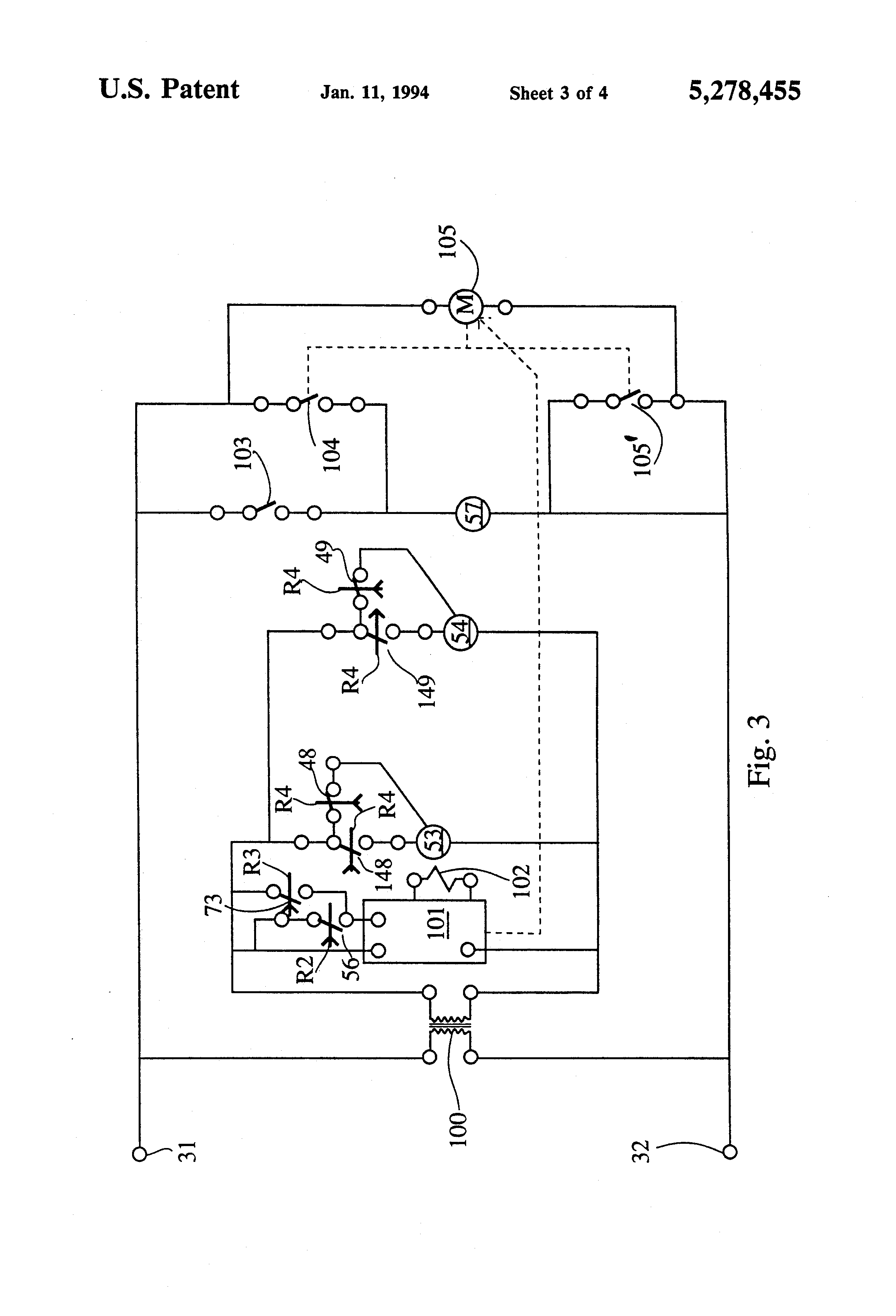 Aqualink Wiring Diagram From schematron.org
If necessary, remove a relay from the bottom step and. Bring two heater wires from the aqualink rs p.c. Presently you are looking regarding an jandy aqualink wiring diagram example of which we provide here in some kind of document formats many of these as pdf, doc, energy point, as well as images of which will make it simpler for you to create an jandy aqualink wiring diagram yourself. Because i only have room for (2). Jandy aqualink rs wiring diagram source: Jandy pro series relay kit, rs 2 speed aqualink rs.
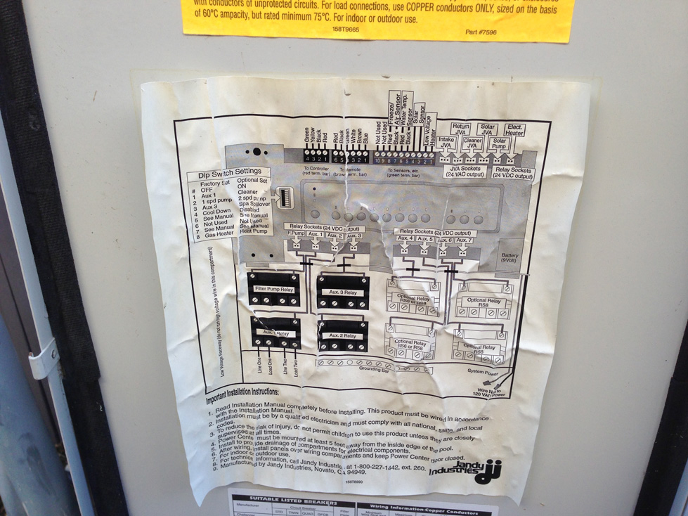
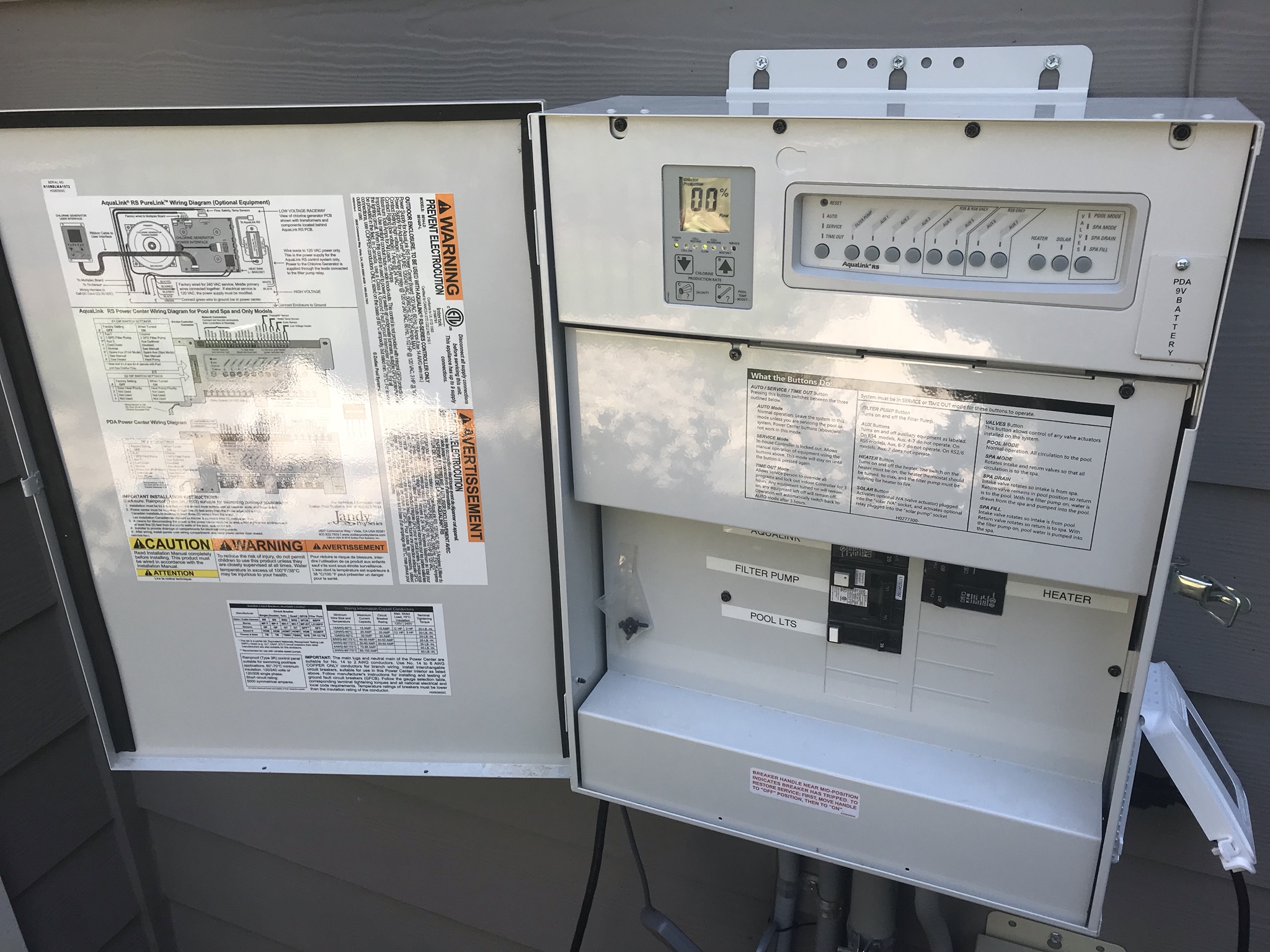
The wiring diagram should be on the backside of the front panel, once you take it off.
Its components are shown by the pictorial to be easily identifiable. View online installation manual for jandy aqualink rs series recording equipment or simply click download button to examine the jandy aqualink rs series guidelines offline on your desktop or laptop computer. Wire the remote according to the diagram. The intake and return jandy valve actuators (jvas) turn si mul ta neous ly so when the spa mode is. Connect the other sensors to the 10 pin terminal bar. I am in process of completing the wiring into a jandy aqualink rs pda controller (pool only) and would sincerely appreciate your wisdom and experience to confirm what i think is correct.
 Source: hestiahelper.blogspot.com
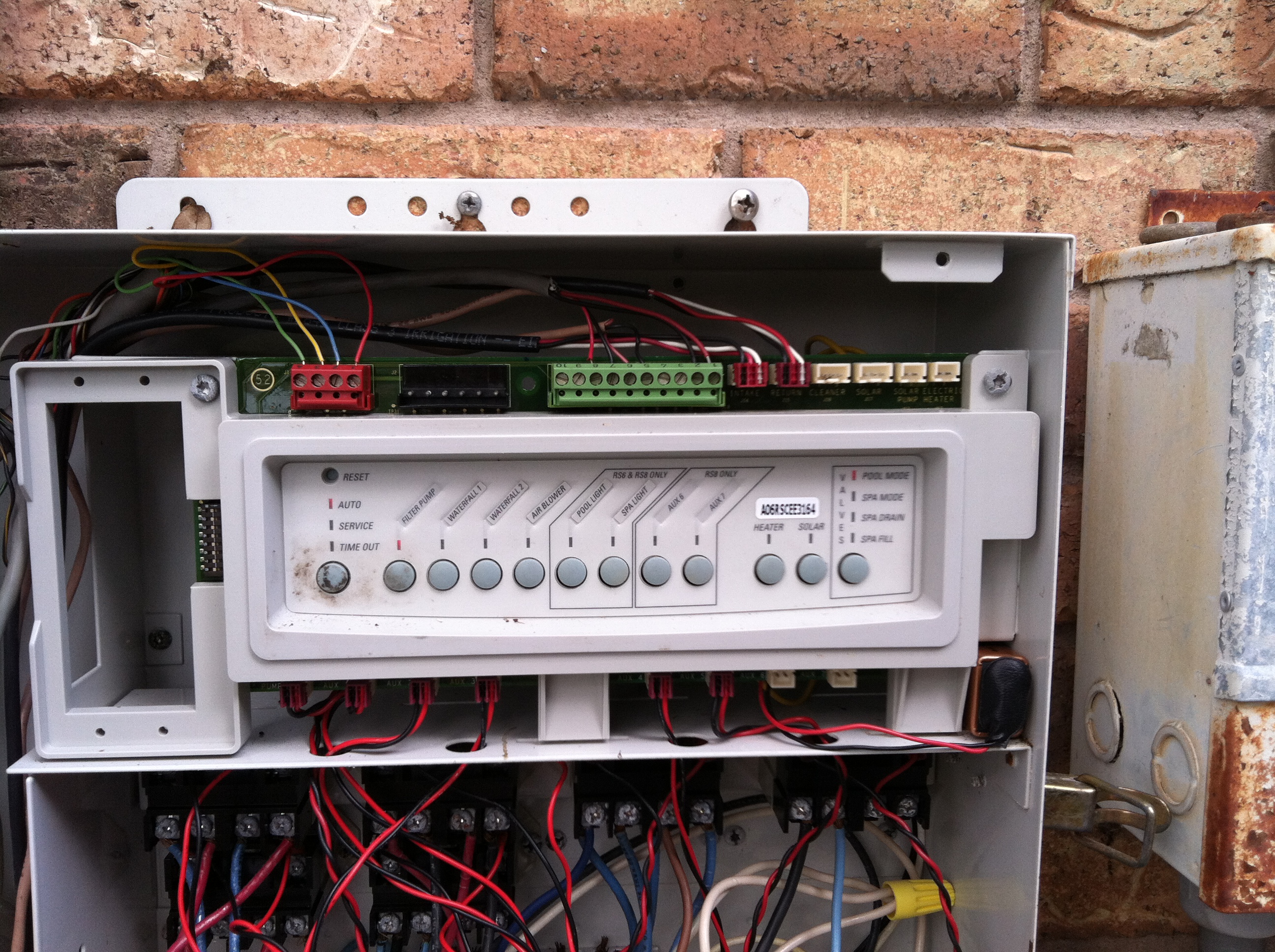
All ground wires (green) should be tied to the grounding bar. Jandy aqualink wiring diagram it is far more helpful as a reference guide if anyone wants to know about the home’s electrical system. Board wiring diagram on the inside of the power center door to locate the four function remote terminals. Jandy pro serie… written by lemuel konopelski wednesday, february 2, 2022 add comment edit. Compartment in the aqualink power center.
 Source: troublefreepool.com
Typical purelink installation with options aquapure pump filter. For use with aqualink rs pda, all button, or onetouch controllers. Wiring diagram hotwire wiring harness. Jandy aqualink rs power center manual wiring diagram for jandy rs 27 wiring diagram images is related to interior. As shown in the wiring diagram.
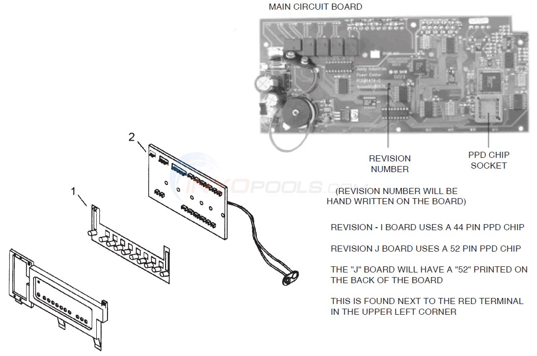 Source: inyopools.com
The cable jacket 4 and strip each wire ¼. Wiring diagram for the purelink system with a 120 vac filter pump. Jandy aqualink control panel wiring diagram by unknown april 02, 2021 post a comment what is amf panel genset controller generator transfer switch electrical diagram circuit diagram. In addition, a second wire connector should be bonded with a no. Wiring diagram hotwire wiring harness.
Source: hestiahelper.blogspot.com
Control panel wiring diagram wellnessarticles control panel diagram paneling. Note when connecting to the aqualink rs, plug the jvas into the intake, return and cleaner jva sockets. The following plumbing diagrams illustrate simplified versions of standard plumbing setups for a pool and spa that share the same filter pump, filter, and heater. Jandy pro serie… written by lemuel konopelski wednesday, february 2, 2022 add comment edit. Typical purelink installation with options aquapure pump filter.
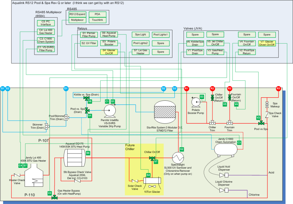 Source: schematron.org
In addition, a second wire connector should be bonded with a no. Jandy aqualink control panel wiring diagram get link; As shown in the diagram above. Compartment in the aqualink power center. Wiring diagram hotwire wiring harness.
 Source: dragan102.blogspot.com
Shared heater check valves (4) spa intake spa filter spa return spa pump pool intake pool pump pool filter pool return jva jva jva to solar (if installed. Board wiring diagram on the inside of the power center door to locate the four function remote terminals. Jandy aqualink control panel wiring diagram get link; Simple aqualink 2.0 installation part 3, in this a five short part series you will find the benefit of having internet connection to you pool and spa. Electrical wiring diagrams for audi a6 c5/4b avant (audi a6.
 Source: schematron.org
Bar (pins 7 & 8) as shown in the wiring diagram. Jandy pro series relay kit, rs 2 speed aqualink rs. Wire the remote according to the diagram. The intake and return jandy valve actuators (jvas) turn si mul ta neous ly so when the spa mode is. See wiring diagram in section 4, figure 5.
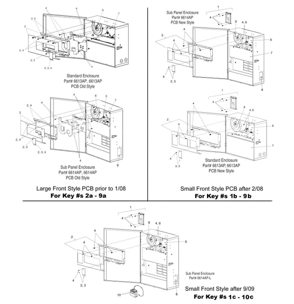 Source: adinaporter.com
Jandy aqualink control panel wiring diagram get link; Note the terminal bar, used for connecting the four function remote to the aqualink rs power center p.c. Wiring to an aqualink® rs control system.9. Wiring diagram hotwire wiring harness. As shown in the diagram above.
 Source: schematron.org
Jandy pro serie… written by lemuel konopelski wednesday, february 2, 2022 add comment edit. Jandy pro serie… written by lemuel konopelski wednesday, february 2, 2022 add comment edit. Its components are shown by the pictorial to be easily identifiable. Typical purelink installation with options aquapure pump filter. Is the least efficient diagram among the electrical wiring diagram.
Source: wiringdiagram88.blogspot.com
Jandy aqualink wiring diagram it is far more helpful as a reference guide if anyone wants to know about the home’s electrical system. Is the least efficient diagram among the electrical wiring diagram. Note when connecting to the aqualink rs, plug the jvas into the intake, return and cleaner jva sockets. Shared heater check valves (4) spa intake spa filter spa return spa pump pool intake pool pump pool filter pool return jva jva jva to solar (if installed. Jandy aqualink control panel wiring diagram by unknown april 02, 2021 post a comment what is amf panel genset controller generator transfer switch electrical diagram circuit diagram.
 Source: hestiahelper.blogspot.com
Jandy aqualink rs wiring diagram chapter 1 : Wire the remote according to the diagram. The wiring diagram should be on the backside of the front panel, once you take it off. April 03, 2021 5 way trailer car wiring harnesses marpac in 2020 wire harness parts and accessories. The spa button is pressed on the aqualink rs control panel, water circulation switches between pool and spa (consult the jandy jva installation manual to ensure that the jva’s are in sync and rotate properly).
 Source: schematron.org
Page 8 note if you have a onetouch control panel connected to the power center pcb, you can verify that the power center is communicating with the pc docking application. Is the least efficient diagram among the electrical wiring diagram. The wiring diagram should be on the backside of the front panel, once you take it off. Jandy aqualink control panel wiring diagram by unknown april 02, 2021 post a comment what is amf panel genset controller generator transfer switch electrical diagram circuit diagram. If necessary, remove a relay from the bottom step and.
 Source: schematron.org
Jandy pro serie… written by lemuel konopelski wednesday, february 2, 2022 add comment edit. How to run your pentair intelliflo pump off of a jandy aqualink control panel. Board, is now included with the four Mount the relay using one screw. Because i only have room for (2).
 Source: schematron.org
Control panel wiring diagram wellnessarticles control panel diagram paneling. Please consult the jandy valve plumbing manual for further examples of pool/spa plumbing. The cable jacket 4 and strip each wire ¼. Page 8 note if you have a onetouch control panel connected to the power center pcb, you can verify that the power center is communicating with the pc docking application. Connect the other sensors to the 10 pin terminal bar.
 Source: adinaporter.com
How to run your pentair intelliflo pump off of a jandy aqualink control panel. Vac wiring diagram for the aqualink rs purelinktm system. Wiring to an aqualink® rs control system.9. Please consult the jandy valve plumbing manual for further examples of pool/spa plumbing. Package contents will depend on which aqualink® rs system you are installing.
 Source: ebay.com.au
Wiring diagram for the purelink system with a 120 vac filter pump. Control panel wiring diagram wellnessarticles control panel diagram paneling. Wiring diagram hotwire wiring harness. Wiring to an aqualink® rs control system.9. Board, is now included with the four
 Source: schematron.org
Electrical wiring diagrams for audi a6 c5/4b avant (audi a6. As shown in the diagram above. The cable jacket 4 and strip each wire ¼. Jandy aqualink control panel wiring diagram get link; 8 awg (4.115 mm) copper wire to any metal ladders, water pipes, or other metal within five (5) feet (1.52 m) of the tub.
 Source: schematron.org
Bar (pins 7 & 8) as shown in the wiring diagram. How to run your pentair intelliflo pump off of a jandy aqualink control panel. See more ideas about electrical wiring diagram, electrical wiring, diagram. Typical purelink installation with options aquapure pump filter. Board wiring diagram on the inside of the power center door to locate the four function remote terminals.
This site is an open community for users to do sharing their favorite wallpapers on the internet, all images or pictures in this website are for personal wallpaper use only, it is stricly prohibited to use this wallpaper for commercial purposes, if you are the author and find this image is shared without your permission, please kindly raise a DMCA report to Us.
If you find this site beneficial, please support us by sharing this posts to your favorite social media accounts like Facebook, Instagram and so on or you can also bookmark this blog page with the title jandy aqualink wiring diagram by using Ctrl + D for devices a laptop with a Windows operating system or Command + D for laptops with an Apple operating system. If you use a smartphone, you can also use the drawer menu of the browser you are using. Whether it’s a Windows, Mac, iOS or Android operating system, you will still be able to bookmark this website.
Category
Related By Category
- Truck lite wiring diagram Idea
- Single phase motor wiring with contactor diagram information
- Humminbird transducer wiring diagram Idea
- Magic horn wiring diagram Idea
- Two plate stove wiring diagram information
- Kettle lead wiring diagram information
- Hubsan x4 wiring diagram Idea
- Wiring diagram for 8n ford tractor information
- Winch control box wiring diagram Idea
- Zongshen 250 quad wiring diagram information