Interposing relay wiring diagram Idea
Home » Trend » Interposing relay wiring diagram Idea
Your Interposing relay wiring diagram images are ready. Interposing relay wiring diagram are a topic that is being searched for and liked by netizens now. You can Find and Download the Interposing relay wiring diagram files here. Find and Download all royalty-free photos and vectors.
If you’re searching for interposing relay wiring diagram pictures information linked to the interposing relay wiring diagram topic, you have pay a visit to the ideal blog. Our site frequently provides you with suggestions for viewing the maximum quality video and image content, please kindly search and find more informative video articles and images that match your interests.
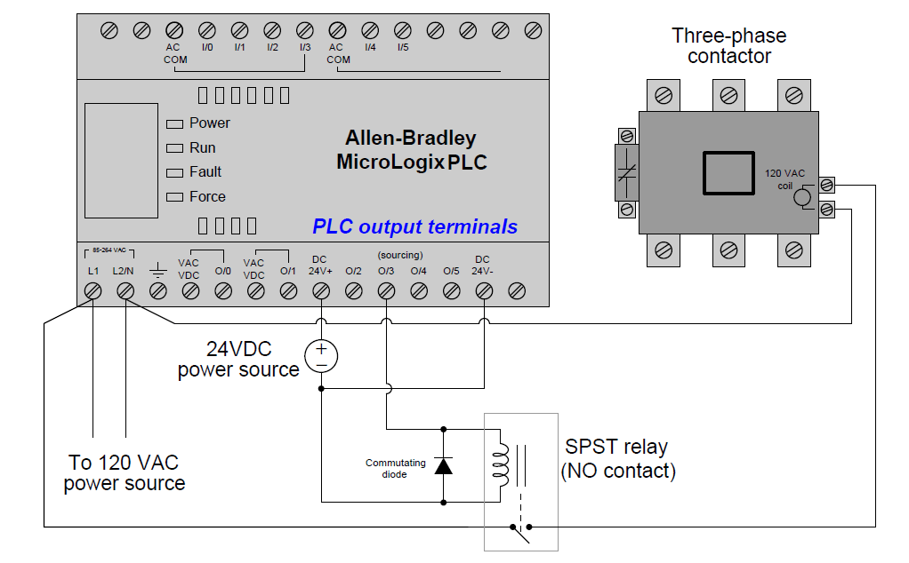
Interposing Relay Wiring Diagram. Standard plc relay outputs will usually have a specification around 0.5 amps of current at 220 volts ac. Log in for pricing and availability. Wiring diagram for interposing relay wiring diagram line wiring diagram wiring diagram line we are make source the schematics, wiring diagrams and technical photos You can use these relays in applications with pumps, compressors, air conditioning, and refrigeration units.
 Emerson Exchange 365 From emersonexchange365.com
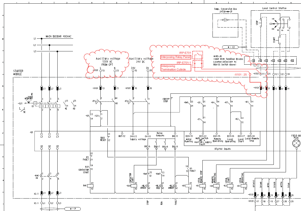
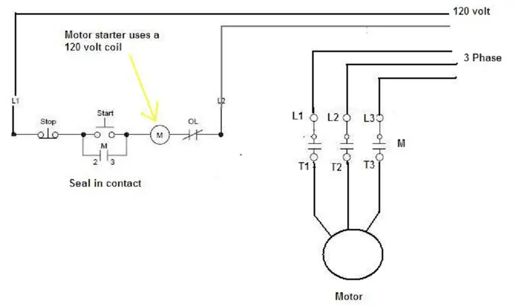
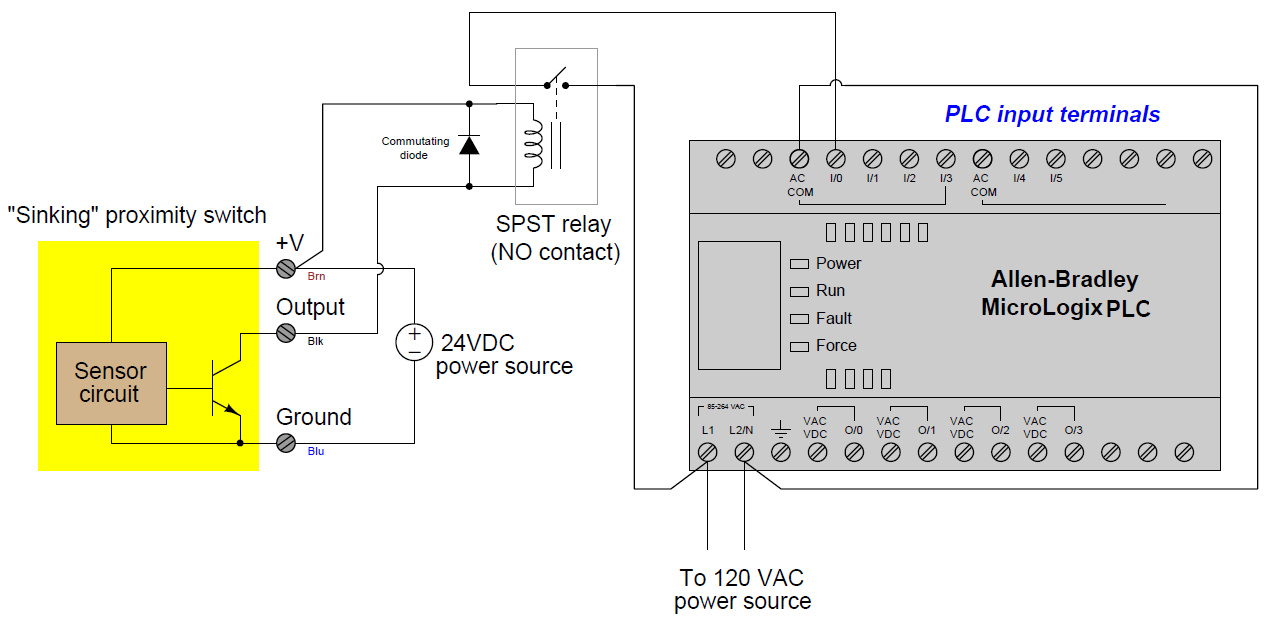
A very common form of schematic diagram showing the interconnection of relays to perform these functions is called a ladder diagram. The following diagram shows an example of an interposing relay connected to a plc output channel: 5 pin is compromised of 3 main. Because relay logic is a hard wired system some sort of wiring diagram or relay schematic diagram is required to make sense of it all. Log in for pricing and availability. This line of interposing relays is designed to fi t a wide range of industrial applications.
12v latching relay wiring diagram.
A 120v supply to #4 terminals on both relays and also the 120v/24v transformer. S70 on/off actuator with interposing relay board (i.r.b.) the back feeding of one actuator by another one wired in parallel is eliminated by using the i.r.b. So in the image below, you’ll see the wire that i am looking for. My current process for fast drawing generation is have a template for di, do , ai, ao, etc or have templates for individual plc cards. In the wiring diagram, it says the tag for the plc input that the push button is connected to is 300u2.1. How to follow an electrical panel wiring diagram?
 Source: accautomation.ca
For example, it uses a single line to represent three phases (hence the name “single line”). In a “ladder” diagram, the two poles of the power source are drawn as vertical rails of a ladder, with horizontal “rungs” showing the switch contacts, relay contacts, relay coils, and final control elements (lamps, solenoid coils, motors) drawn in. These are the tags for the plc inputs and outputs. S70 on/off actuator with interposing relay board (i.r.b.) the back feeding of one actuator by another one wired in parallel is eliminated by using the i.r.b. Log in for pricing and availability.
 Source: allaboutcircuits.com
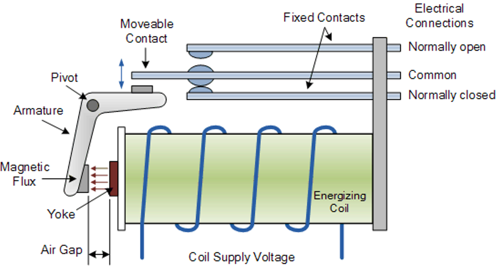
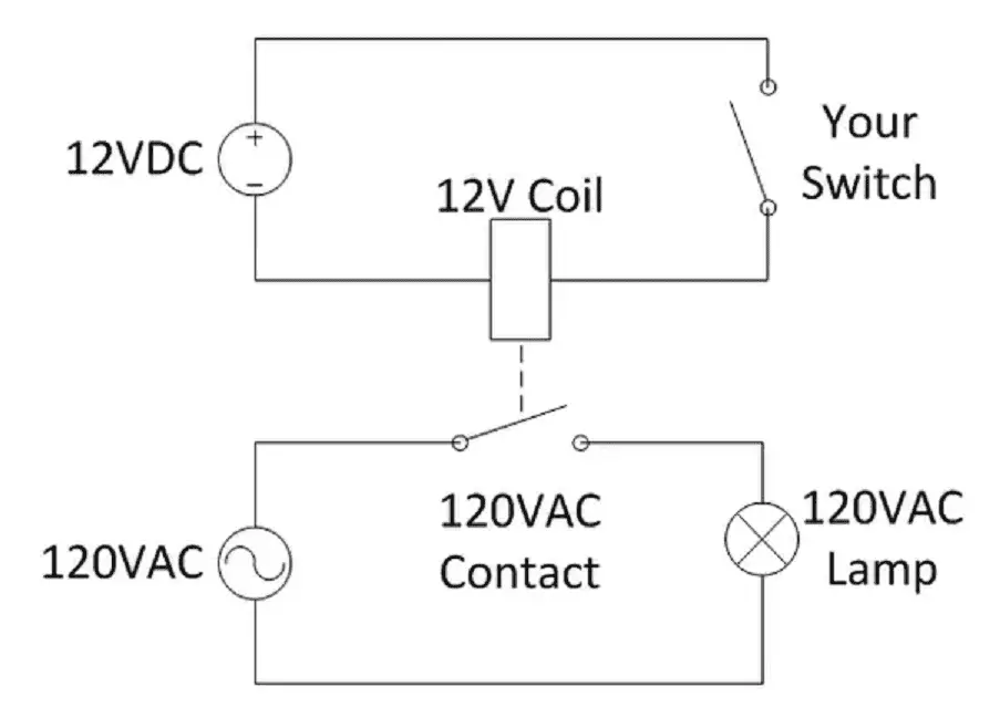
Standard plc relay outputs will usually have a specification around 0.5 amps of current at 220 volts ac. Control voltage control contact e he ch th 1h. An interposing relay is simply an auxiliary relay that is used to isolate two different systems or devices from one another. In this circuit the plc’s transistor outputs can only handle 24 volts dc, and at fairly low current. S70 on/off actuator with interposing relay board (i.r.b.) the back feeding of one actuator by another one wired in parallel is eliminated by using the i.r.b.
 Source: plctalk.net
These are the tags for the plc inputs and outputs. Standard plc relay outputs will usually have a specification around 0.5 amps of current at 220 volts ac. Wiring diagram for interposing relay the wiring diagram. Relay can be the best option to control electrical devices automatically. For example, it uses a single line to represent three phases (hence the name “single line”).
 Source: emersonexchange365.com
There are different kinds of relays for different purposes. Wiring diagram for interposing relay the wiring diagram. For example, it uses a single line to represent three phases (hence the name “single line”). So why do we need to isolate different devices in the first place. Here is a quick interposing relay diagram i found with a quick google image search of interposing relay wiring diagram where as cr aaa is a small relay controlled by the plc output and the contacts from that cr aaa relay control larger field devices.
 Source: accautomation.ca
There are different kinds of relays for different purposes. If we need to switch a solenoid that requires 1.2 amps of current at 220 volts ac, we need a relay that will be able to handle that current and voltage. There are different kinds of relays for different purposes. The pump is connected to #2 terminal on both relays. In a “ladder” diagram, the two poles of the power source are drawn as vertical rails of a ladder, with horizontal “rungs” showing the switch contacts, relay contacts, relay coils, and final control elements (lamps, solenoid coils, motors) drawn in.
 Source: pinterest.com
The following diagram shows an example of an interposing relay connected to a plc output channel: Creating an interposing relay and plc schematic using plc io utility. It is installed onto a standard one gang electrical box with a mounting hole that have 6.5cm spacing. In the wiring diagram, it says the tag for the plc input that the push button is connected to is 300u2.1. 12v latching relay wiring diagram.
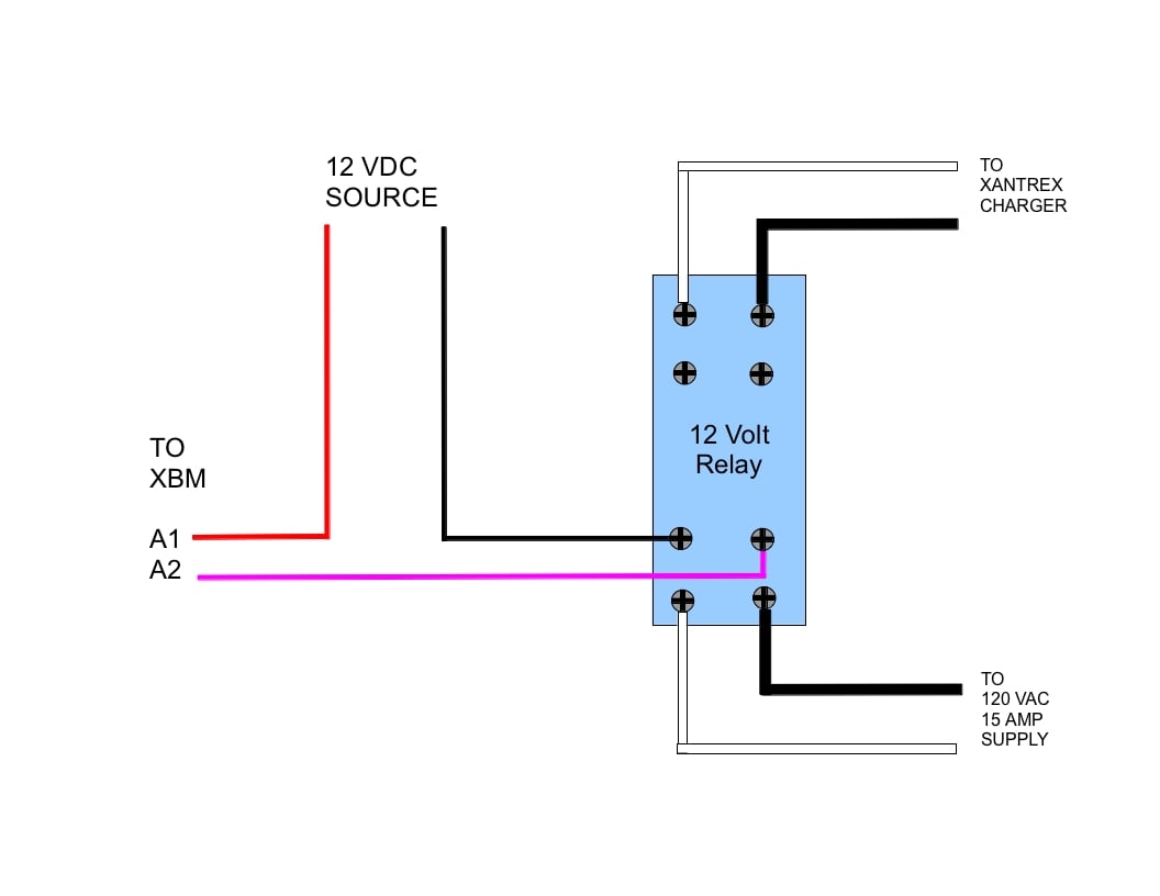 Source: forum.solar-electric.com
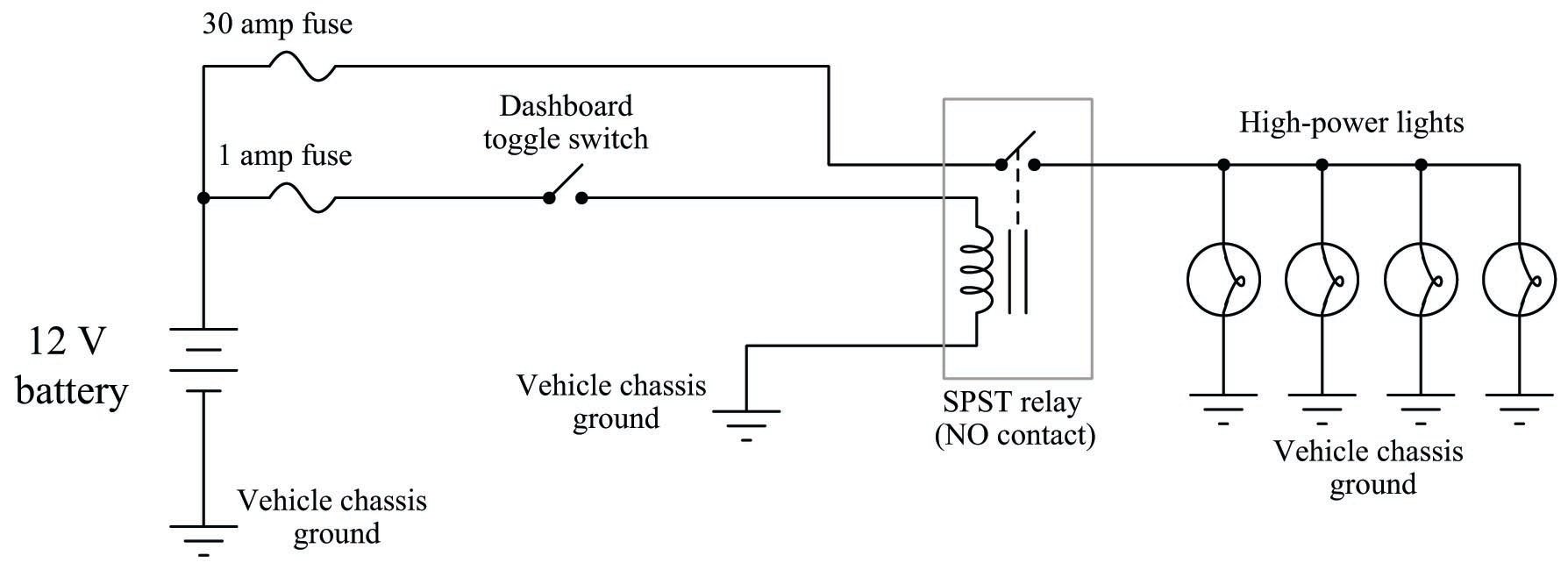
It is installed onto a standard one gang electrical box with a mounting hole that have 6.5cm spacing. You can use these relays in applications with pumps, compressors, air conditioning, and refrigeration units. In this circuit, the relay performs no logic function whatsoever. My main question is how do i generate 120vac and 24vdc on the same drawings and through the plc io utility and its spreadsheet. So in the image below, you’ll see the wire that i am looking for.
 Source: plctalk.net
It can be used for various switching. Now based on the diagram i need to look for a wire that is tagged as 2. There are different kinds of relays for different purposes. The standard d20ki interposing relay panel is equipped with p&b kuep and kup interposing relays (10 a at 150 vdc and 10 a at 240 vac respectively). Voltage levels which may be induced onto the pilot wires.

Control voltage control contact e he ch th 1h. Repeat the above steps for each do signal and highlight each signal in the i/o list to ensure all the do signals are covered under the test. It is installed onto a standard one gang electrical box with a mounting hole that have 6.5cm spacing. This line of interposing relays is designed to fi t a wide range of industrial applications. Interposing and supervision relays 7pg17.
 Source: afruitfulfinddd.blogspot.com
The diagram above is the 5 pin relay wiring diagram. S70 on/off actuator with interposing relay board (i.r.b.) the back feeding of one actuator by another one wired in parallel is eliminated by using the i.r.b. Now based on the diagram i need to look for a wire that is tagged as 2. So why do we need to isolate different devices in the first place. The interposing relays are intended for the remote control operation of switchgear over pilot wires with a maximum resistance of 200 ohms.
 Source: wiringdiagramall.blogspot.com
Log in for pricing and availability. Let’s consider a scenario where we have the need operate a device that requires 120vac, but the plc in which we need to control this device can only output 24vdc. S70 on/off actuator with interposing relay board (i.r.b.) the back feeding of one actuator by another one wired in parallel is eliminated by using the i.r.b. It can be used for various switching. Interposing and supervision relays 7pg17.
 Source: instrumentationtools.com
Standard plc relay outputs will usually have a specification around 0.5 amps of current at 220 volts ac. It is installed onto a standard one gang electrical box with a mounting hole that have 6.5cm spacing. The pump is connected to #2 terminal on both relays. Wiring diagram for interposing relay wiring diagram line wiring diagram wiring diagram line we are make source the schematics, wiring diagrams and technical photos Standard plc relay outputs will usually have a specification around 0.5 amps of current at 220 volts ac.
 Source: etechnog.com
Wiring diagram for interposing relay wiring diagram line wiring diagram wiring diagram line we are make source the schematics, wiring diagrams and technical photos It can be used for various switching. Check and ensure the continuity at the mcc end for the same signal using a multimeter. The following diagram shows an example of an interposing relay connected to a plc output channel: In this circuit, the relay performs no logic function whatsoever.
 Source: articleshook.com
Automotive relays mini relayspcb relayspower relayslatching relayssolendoid water valve automotive connector and harness. Interposing and supervision relays 7pg17. The alternating feature lets you select the primary or secondary load or to alternate between the two. Voltage levels which may be induced onto the pilot wires. Wiring diagram for interposing relay wiring diagram line wiring diagram wiring diagram line we are make source the schematics, wiring diagrams and technical photos
 Source: articleshook.com
The relays are designed so that they are not susceptible to certain a.c. My main question is how do i generate 120vac and 24vdc on the same drawings and through the plc io utility and its spreadsheet. Hope the above explanation for the wiring and testing of the interposing relay panel is understood. A very common form of schematic diagram showing the interconnection of relays to perform these functions is called a ladder diagram. Log in for pricing and availability.
 Source: control.com
Automotive relays mini relayspcb relayspower relayslatching relayssolendoid water valve automotive connector and harness. Standard plc relay outputs will usually have a specification around 0.5 amps of current at 220 volts ac. Log in for pricing and availability. In the wiring diagram, it says the tag for the plc input that the push button is connected to is 300u2.1. Hope the above explanation for the wiring and testing of the interposing relay panel is understood.
 Source: schematicandwiringdiagram.blogspot.com
Log in for pricing and availability. The pump is connected to #2 terminal on both relays. Log in for pricing and availability. S70 on/off actuator with interposing relay board (i.r.b.) the back feeding of one actuator by another one wired in parallel is eliminated by using the i.r.b. The standard d20ki interposing relay panel is equipped with p&b kuep and kup interposing relays (10 a at 150 vdc and 10 a at 240 vac respectively).
 Source: instrumentationtools.com
Automotive relays mini relayspcb relayspower relayslatching relayssolendoid water valve automotive connector and harness. My main question is how do i generate 120vac and 24vdc on the same drawings and through the plc io utility and its spreadsheet. These are the tags for the plc inputs and outputs. Because relay logic is a hard wired system some sort of wiring diagram or relay schematic diagram is required to make sense of it all. Wiring interposing relays npn pnp isolation acc automation wet and dry contact relay explanation and case study interposing relay application advantages function 1 in the block diagram an interposing relay is used chegg com diagram 12 volt fuel pump relay wiring diagram full version plc discrete i o modules plc instrumentation forum
This site is an open community for users to do submittion their favorite wallpapers on the internet, all images or pictures in this website are for personal wallpaper use only, it is stricly prohibited to use this wallpaper for commercial purposes, if you are the author and find this image is shared without your permission, please kindly raise a DMCA report to Us.
If you find this site adventageous, please support us by sharing this posts to your preference social media accounts like Facebook, Instagram and so on or you can also save this blog page with the title interposing relay wiring diagram by using Ctrl + D for devices a laptop with a Windows operating system or Command + D for laptops with an Apple operating system. If you use a smartphone, you can also use the drawer menu of the browser you are using. Whether it’s a Windows, Mac, iOS or Android operating system, you will still be able to bookmark this website.
Category
Related By Category
- Predator 670 engine wiring diagram Idea
- Frsky x8r wiring diagram information
- Pioneer ts wx130da wiring diagram Idea
- Johnson 50 hp wiring diagram Idea
- Kohler voltage regulator wiring diagram Idea
- Johnson 50 hp outboard wiring diagram information
- Kti hydraulic remote wiring diagram Idea
- Pyle plpw12d wiring diagram information
- Tx9600ts wiring diagram information
- Lifan 50cc wiring diagram information