Intermittent pilot ignition wiring diagram Idea
Home » Trending » Intermittent pilot ignition wiring diagram Idea
Your Intermittent pilot ignition wiring diagram images are available in this site. Intermittent pilot ignition wiring diagram are a topic that is being searched for and liked by netizens now. You can Find and Download the Intermittent pilot ignition wiring diagram files here. Find and Download all royalty-free photos and vectors.
If you’re searching for intermittent pilot ignition wiring diagram pictures information connected with to the intermittent pilot ignition wiring diagram interest, you have come to the ideal site. Our site always gives you hints for refferencing the highest quality video and image content, please kindly surf and locate more informative video content and images that match your interests.
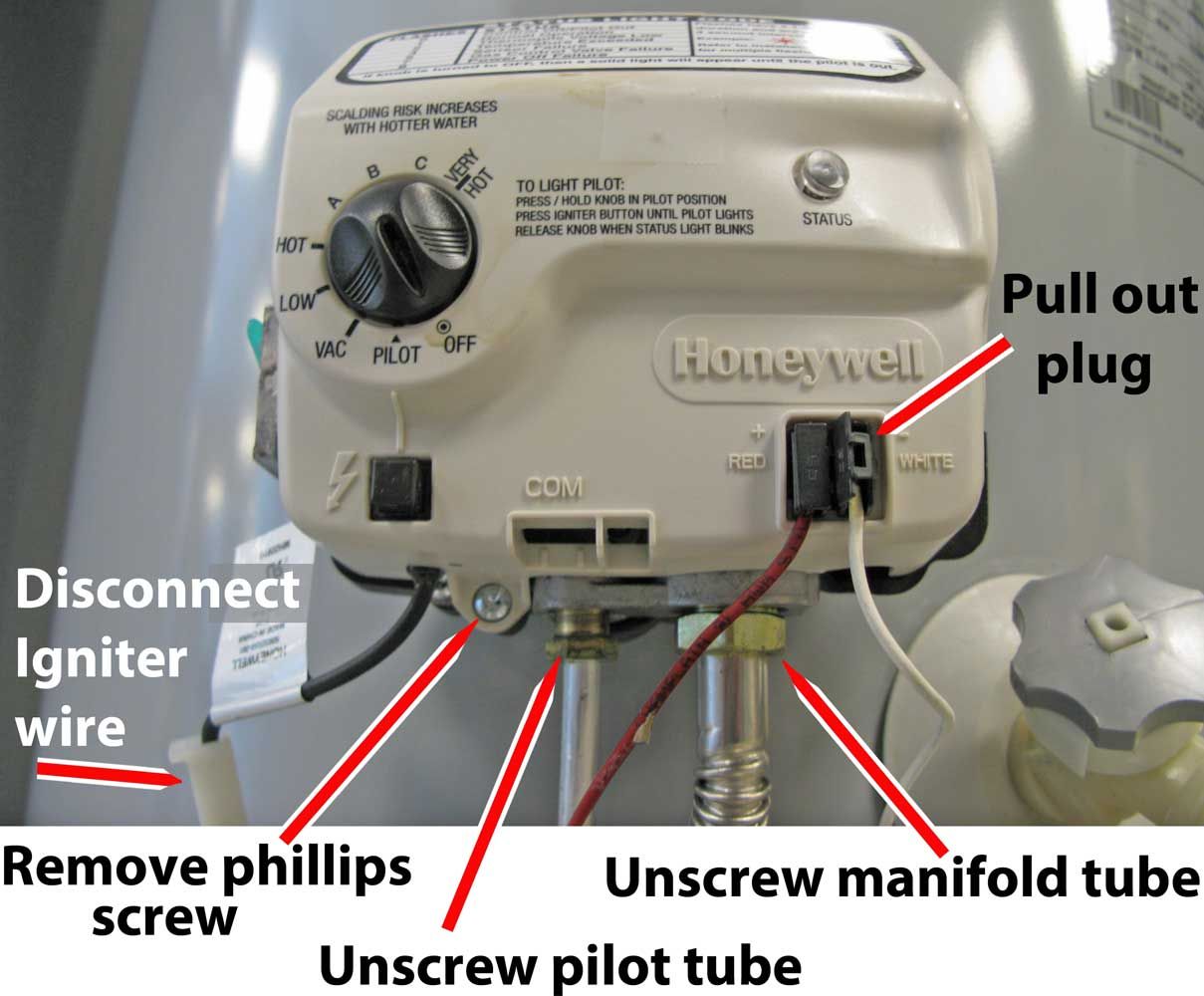
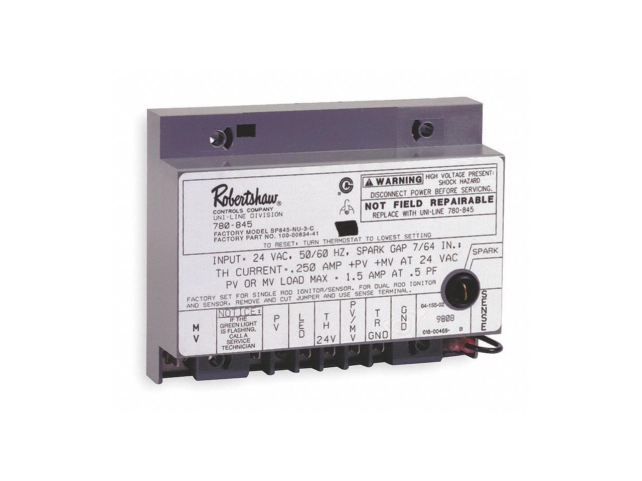
Intermittent Pilot Ignition Wiring Diagram. Pilot gas provides labels to help assure proper marking of the wires. These additional terminals are not shown in this diagram.ahe; Pilot gas is ignited and burns during each run cycle (intermittent pilot). Main burner and pilot gas are extinguished during the off cycle.
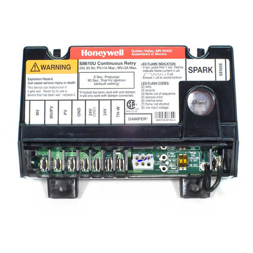
 Honeywell S8610U3009/U. Universal Intermittent Pilot From ebay.com
The spark gap on most systems, from the tip of the igniter to the ground connection, is 1/8 in. Ignition trial/delay sequence is repeated until the appliance lights or call for heat is removed. These additional terminals are not shown in this diagram.ahe; Wire per wiring diagrams on reverse side. Check all wiring for proper connections and make sure your system is properly grounded, including the pilot burner igniter. The g67 intermittent pilot ignition control is used to automatically light a pilot burner and energize the main burner gas valve of a heating system in response to the thermostats call for heat.
Ahe user manual ( kb):
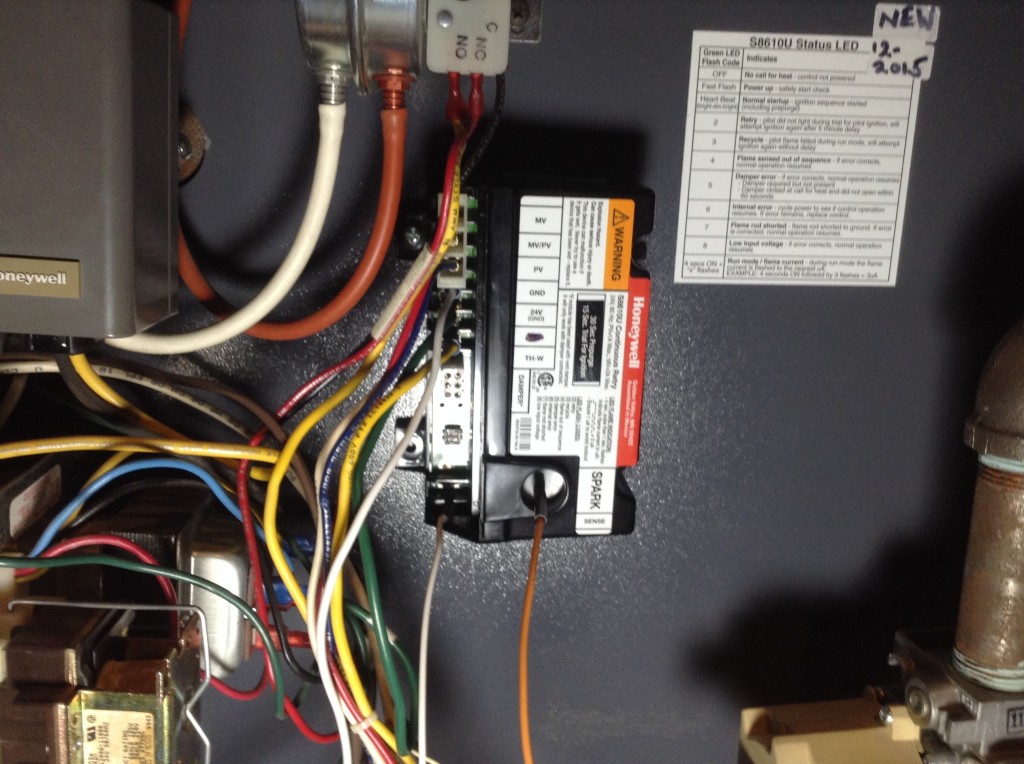
With no trouble at all. Intermittent pilot modules s8600, s8610, s8660, s8670 application these ignition modules provide ignition sequence, flame monitoring and safety shutoff for intermittent pilot central furnaces and heating appliances. Wiring l8148e1265 with internal plug directly to vent damper in hydronic intermittent pilot system. S8610 and s8670 provide up to 1.0 a pilot and 2.0 Pilot gas provides labels to help assure proper marking of the wires. Honeywell s8610u3009 universal intermittent pilot ignition module for honeywell s8610u wiring diagram, image size 541 x 541 px, and to view image details please click the image.
 Source: bostonheatingsupply.com
I ordered a replacement one. The su universal replacement ignition module is. The g67 intermittent pilot ignition control is used to automatically light a pilot burner and energize the main burner gas valve of a heating system in response to the thermostats call for heat. However, with everything else now days, the newer one does not match the older one. The “main control module” acts like an “operating system” of a computer and controls all primary functions of the ipi system (i.e.
 Source: supplyhouse.com
The “extension module” controls the fan and auxiliary lighting powered by 120vac. Intermittent pilot ignition wiring diagram wiring diagram is a simplified normal pictorial representation of an electrical circuit. Pilot gas provides labels to help assure proper marking of the wires. The spark gap on most systems, from the tip of the igniter to the ground connection, is 1/8 in. Bg1600m intermittent pilot ignition control this model is configured to replace the s8670d 15 sec trial until lockout prepurge:

Q refer to the wiring diagram and. That graphic (honeywell s8610u3009 universal intermittent pilot ignition module for honeywell s8610u wiring diagram) over can be branded along with: Check the wiring diagram furnished by the. Q locate the components needed for this lab and mount them on the trainer. Attached.my assumption (confirmed via wiring diagram) is that 25v (1) is hot and 25v (2) is ground.

Flame monitoring and safety shutoff for intermittent pilot warm air furnaces and heating appliances provides 100 percent pilot gas shutoff if pilot fails to light; S8610 and s8670 provide up to 1.0 a pilot and 2.0 Taking into consideration aggravating to remove, replace or repair the wiring in an automobile, having an accurate and detailed intermittent pilot. I ordered a replacement one. That graphic (honeywell s8610u3009 universal intermittent pilot ignition module for honeywell s8610u wiring diagram) over can be branded along with:
 Source: daewoowiringdiagram.blogspot.com
The burden really is that every car is different. Pilot gas is ignited and burns during each run cycle (intermittent pilot). Pilot gas provides labels to help assure proper marking of the wires. Q refer to the wiring diagram and. White rodgers aquastat wiring diagram wiring diagram steam boiler boiler boiler installation.

I ordered a replacement one. I ordered a replacement one. Perform the checkout section before leaving the installation. Submitted through admin on january, 3 2016. G775 rjd 14 g775 rjd 15 jci johnson controls to baso intermittent pilot ignition ipi control with rollout switch g77xrjx series to bg1600m0 series with remote sense and r o.
 Source: wiringschemas.blogspot.com
Wire per wiring diagrams on reverse side. Ignition trial/delay sequence is repeated until the appliance lights or call for heat is removed. Verify the sequence of operation. The intermittent pilot ignition control is short cycling. 4 g600 series replacement intermittent pilot ignition controls installation instructions setup and adjustments commissioning the anticipator setting is normally equal to the ignition system current draw, plus that of the pilot and main valve.
 Source: diagramweb.net
The g776rgd 14 ignition control kit can only be used to replace a lennox g20 g20r g23 and g26 series unit that has a johnson controls g776rgd 1. The “main control module” acts like an “operating system” of a computer and controls all primary functions of the ipi system (i.e. However, with everything else now days, the newer one does not match the older one. All applications must use a redundant main gas valve. Automatic gas ignition system components shall be installed so these components will not be subjected to dripping water during installation or service.
 Source: ebay.com
Following a pain to remove, replace or repair the wiring in an automobile, having an accurate and detailed auxiliary reverse lights wiring diagram is vital. Wire per wiring diagrams on reverse side. View and download honeywell su installation instructions manual online. Honeywell s8610u3009 universal intermittent pilot ignition module for honeywell s8610u wiring diagram, image size 541 x 541 px, and to view image details please click the image. Trial for ignition is repeated.
 Source: wiringschemas.blogspot.com
• to connect the vent damper, the wire from pin 1 should be connected to 24vac hot from the supply transformer. Ahe user manual ( kb): Be sure the system is properly grounded, including ground connection to the pilot burner. If the spark will jump across ½ in. Flame monitoring and safety shutoff for intermittent pilot warm air furnaces and heating appliances provides 100 percent pilot gas shutoff if pilot fails to light;
 Source: walmart.com
Refer to the wiring section for electrical connections and wiring diagrams. Trial for ignition is repeated. Ahe fenwal ignition sensing control system wiring diagram ( kb): S8610 and s8670 provide up to 1.0 a pilot and 2.0 Honeywell s8610u3009 universal intermittent pilot ignition module for honeywell s8610u wiring diagram, image size 541 x 541 px, and to view image details please click the image.

Wiring diagram for g67b( ) These additional terminals are not shown in this diagram.ahe; The ignition control module’s operation is divided into two phases: Perform the checkout section before leaving the installation. This should be the only wire attached to the ths terminal.
 Source: supplyhouse.com
Be sure the system is properly grounded, including ground connection to the pilot burner. Due to variations in appliance wiring and valves, it is advisable to measure the actual current draw of the Do not connect the thermostat wires to the control board until wiring is verified. That graphic (honeywell s8610u3009 universal intermittent pilot ignition module for honeywell s8610u wiring diagram) over can be branded along with: The “main control module” acts like an “operating system” of a computer and controls all primary functions of the ipi system (i.e.
 Source: vustudy.com
Ignition trial/delay sequence is repeated until the appliance lights or call for heat is removed. 8 g67 intermittent pilot ignition controls technical bulletin y75 flame sensor thermostat power supply 24 vac 1 2 4 3 high voltage cable high limits in this line only jumper pilot burner ground ground terminals mv pv 5 power is wired directly to r (common) on the thermostat. Wire per wiring diagrams on reverse side. The main gas valve will not open until the pilot flame has been proven by the sensing circuit. The su universal replacement ignition module is.

With good intensity, it should be able to jump across 1/8 in. Ahe parts list ( kb): Honeywell s8610u3009 universal intermittent pilot ignition module for honeywell s8610u wiring diagram, image size 541 x 541 px, and to view image details please click the image. • to connect the vent damper, the wire from pin 1 should be connected to 24vac hot from the supply transformer. Verify the sequence of operation.
 Source: newegg.com
Pilot gas provides labels to help assure proper marking of the wires. To find out just about all pictures within honeywell s8610u wiring diagram photographs gallery make sure you comply with this specific hyperlink. With no trouble at all. Trial for ignition is repeated. Ahe white rodgers ignition sensing control system wiring.
 Source: reddit.com
However, with everything else now days, the newer one does not match the older one. Q refer to the wiring diagram and. View and download honeywell su installation instructions manual online. Pilot gas provides labels to help assure proper marking of the wires. Honeywell s8610u3009 universal intermittent pilot ignition module for honeywell s8610u wiring diagram, image size 541 x 541 px, and to view image details please click the image.
 Source: galvinconanstuart.blogspot.com
Check all wiring for proper connections and make sure your system is properly grounded, including the pilot burner igniter. View and download honeywell su installation instructions manual online. Pilot gas provides labels to help assure proper marking of the wires. Ahe white rodgers ignition sensing control system wiring. Ahe fenwal ignition sensing control system wiring diagram ( kb):
This site is an open community for users to do submittion their favorite wallpapers on the internet, all images or pictures in this website are for personal wallpaper use only, it is stricly prohibited to use this wallpaper for commercial purposes, if you are the author and find this image is shared without your permission, please kindly raise a DMCA report to Us.
If you find this site adventageous, please support us by sharing this posts to your favorite social media accounts like Facebook, Instagram and so on or you can also save this blog page with the title intermittent pilot ignition wiring diagram by using Ctrl + D for devices a laptop with a Windows operating system or Command + D for laptops with an Apple operating system. If you use a smartphone, you can also use the drawer menu of the browser you are using. Whether it’s a Windows, Mac, iOS or Android operating system, you will still be able to bookmark this website.
Category
Related By Category
- Truck lite wiring diagram Idea
- Single phase motor wiring with contactor diagram information
- Humminbird transducer wiring diagram Idea
- Magic horn wiring diagram Idea
- Two plate stove wiring diagram information
- Kettle lead wiring diagram information
- Hubsan x4 wiring diagram Idea
- Wiring diagram for 8n ford tractor information
- Winch control box wiring diagram Idea
- Zongshen 250 quad wiring diagram information