Intermatic t104 timer wiring diagram Idea
Home » Trending » Intermatic t104 timer wiring diagram Idea
Your Intermatic t104 timer wiring diagram images are available. Intermatic t104 timer wiring diagram are a topic that is being searched for and liked by netizens now. You can Get the Intermatic t104 timer wiring diagram files here. Find and Download all royalty-free photos.
If you’re searching for intermatic t104 timer wiring diagram pictures information connected with to the intermatic t104 timer wiring diagram topic, you have come to the ideal site. Our site frequently gives you suggestions for downloading the maximum quality video and picture content, please kindly surf and locate more informative video content and images that match your interests.
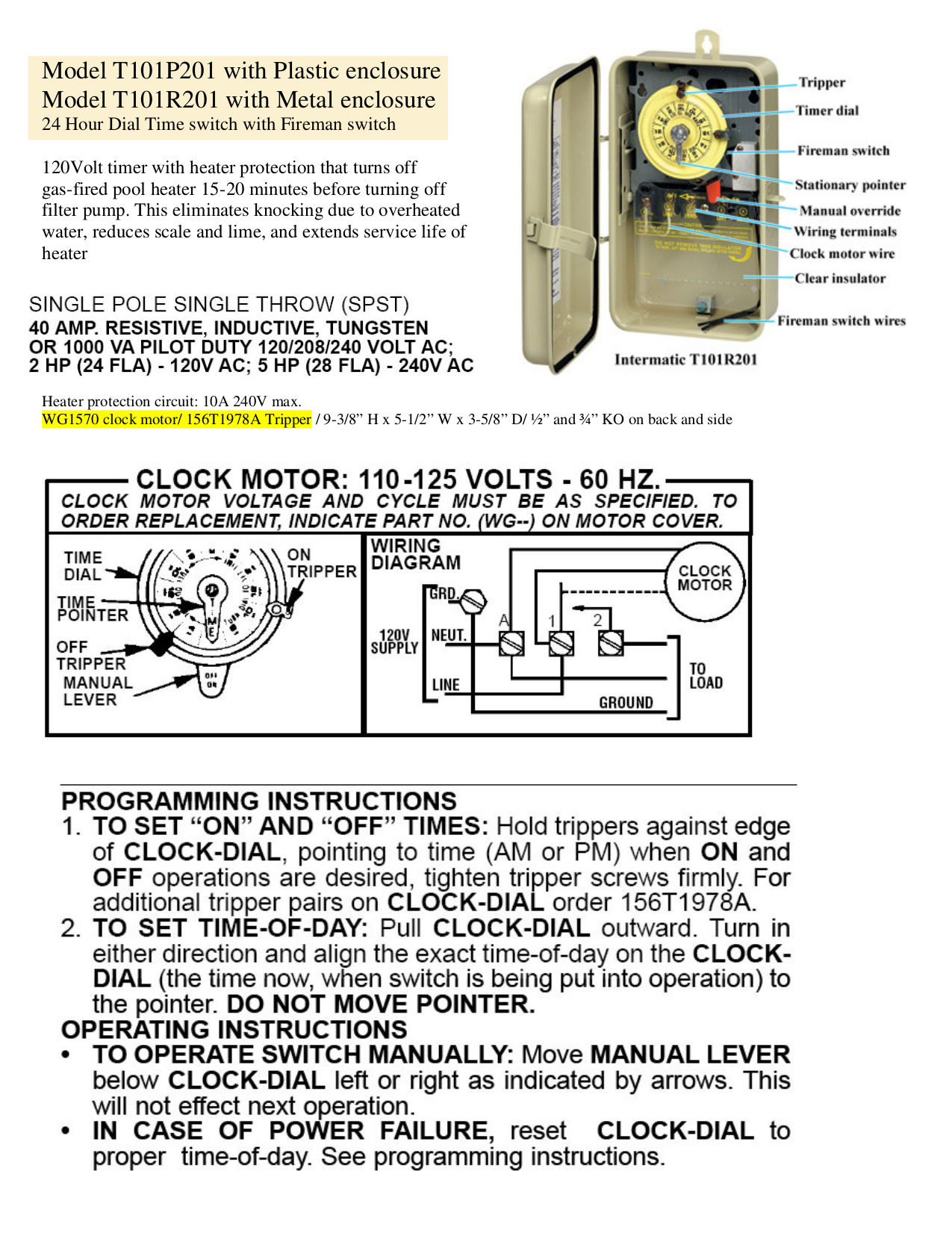
Intermatic T104 Timer Wiring Diagram. Wiring instructions:to wire switch follow diagram above. Lr ul moving the clock hands can damage the timer. Intermatic t101 timer wiring diagram. T, t & t are volt timers.

Intermatic t basic wiring diagram, t timer volts or volts check label on side of water heater for volts & watts this timer. T has wg v clock motor. These dependable time switches can handle electrical loads up to 40 a per. Assortment of intermatic timer t104 wiring diagram. The pump is a gould 240v jrs 10 jet pump with a hayward label on it. T timer requires neutral wire.
The pump is a gould 240v jrs 10 jet pump with a hayward label on it.
T104 intermatic 250v time clock. Grässlin uk connect wiring in accordance with wiring diagram. I disconnected the old manual switch and installed the t 104 timer switch. T104 24 hour dial time switch type 1 indoor use only Moving the clock hands can damage the timer. T & t are volt timers;
 Source: wholefoodsonabudget.com
Unique t104m timer wiring diagram white neutral wire famous pool. Apr 21, 2009, 01:48 pm. I disconnected the old manual switch and installed the t 104 timer switch. It reveals the components of the circuit as streamlined forms, and also the power and also signal connections in between the tools. The pump is a gould 240v jrs 10 jet pump with a hayward label on it.
 Source: schematron.org
I have recently decided to install a timer for our pool pump to replace the manual switch that was there before. While the intermatic t104 has a manual switch, it is through a gate, down some stares, through a door into the equipment room/bodega. T has wg v clock motor. Unique t104m timer wiring diagram white neutral wire famous pool. Get a 21 ft round 52 in deep pretium above ground pool kit direct from pool warehouse.
 Source: strawberry-sweet.blogspot.com
Assortment of intermatic timer t104 wiring diagram. T104 intermatic 250v time clock. A wiring diagram is a simplified standard photographic depiction of an electric circuit. Assortment of intermatic timer t104 wiring diagram. Wiring instructions:to wire switch follow diagram above.
 Source: wholefoodsonabudget.com
Wiring instructions:to wire switch follow diagram above. Click the register link above to proceed. Wiring diagram line we are make source the schematics, wiring diagrams and technical photos. Apr 21, 2009, 01:48 pm. Wiring diagram 240 v 2 wire and ground lr3730 document1 10/30/03 1:36 pm page 1.
 Source: pinterest.com
Pool pump timer bypass in 240v system intermatic wiring t101r t104 off controller box for with heater delay circuit basic. A decade ago, the folks that build my pool installed a bypass switch for the 240v pool pump timer. Wiring diagram 240 v 2 wire and ground clock motor: It reveals the components of the circuit as streamlined forms, and also the power and also signal connections in between the tools. I have recently decided to install a timer for our pool pump to replace the manual switch that was there before.
 Source: wholefoodsonabudget.com
A wiring diagram is a simplified standard photographic depiction of an electric circuit. The key.jul 18, · t timer wiring diagram intermatic wall timer instructions intermatic wall timer instructions buy now model overview specifications resources digital timer with astro random and dst features 7 on. Wiring diagram 240 v 2 wire and ground clock motor: Clock motor voltage and cycle must be as specified. T, t & t are volt timers.
 Source: whatmindsaid.blogspot.com
As my pool has two infinity edges, it needs. Use solid or stranded copper only wire. While the intermatic t104 has a manual switch, it is through a gate, down some stares, through a door into the equipment room/bodega. Moving the clock hands can damage the timer. Pool pump timer bypass in 240v system intermatic wiring t101r t104 off controller box for with heater delay circuit basic.
 Source: wholefoodsonabudget.com
I have recently decided to install a timer for our pool pump to replace the manual switch that was there before. As my pool has two infinity edges, it needs. I disconnected the old manual switch and installed the t 104 timer switch. T timer requires neutral wire. Get intermatic timer t104 wiring diagram sample.
 Source: usermanual.wiki
A decade ago, the folks that build my pool installed a bypass switch for the 240v pool pump timer. Open following links for troubleshooting, wiring, manuals, and replacement parts: Lighting contactor wiring diagram with timer. Irish connections a magazine cover for the irish worldwide. A decade ago, the folks that build my pool installed a bypass switch for the 240v pool pump timer.
 Source: galvinconanstuart.blogspot.com
Assortment of intermatic timer t104 wiring diagram. Intermatic timer t104 wiring diagram wiring diagram is a simplified tolerable pictorial representation of an electrical circuit. Get intermatic timer t104 wiring diagram sample. It reveals the components of the circuit as streamlined forms, and also the power and also signal connections in between the tools. Intermatic t104 wiring diagram wiring diagram line wiring diagram.
 Source: galvinconanstuart.blogspot.com
Intermatic t101 timer wiring diagram. Wiring diagram line we are make source the schematics, wiring diagrams and technical photos. T104 replacement parts more box timers how to wire timers. Unique t104m timer wiring diagram white neutral wire famous pool. Intermatic t104 wiring (simple terms) i am trying to wire an intematic timer model #t104 to my pool pump.
 Source: waterheatertimer.org
Intermatic t104 pool timer off tripper turns the clock doityourself com community forums series 40 amp 208 277 volt dpst 24 hour mechanical time switch mechanism. Intermatic timer t104 wiring diagram wiring diagram is a simplified tolerable pictorial representation of an electrical circuit. Intermatic t101 timer wiring diagram. With diagram t104r won t turn pump on but does it off doityourself com community forums t101p201 instruction manual t104 indoor 24 hour dial 208v 277v 40 amp 2 poles changing in. The pump is a gould 240v jrs 10 jet pump with a hayward label on it.
 Source: ebay.com
These dependable time switches can handle electrical loads up to 40 a per. Unique t104m timer wiring diagram white neutral wire famous pool. Assortment of intermatic timer t104 wiring diagram. T104 intermatic 250v time clock. A wiring diagram is a simplified standard photographic depiction of an electric circuit.
 Source: wholefoodsonabudget.com
Irish connections a magazine cover for the irish worldwide. Wiring instructions:to wire switch follow diagram above. I have recently decided to install a timer for our pool pump to replace the manual switch that was there before. T104 24 hour dial time switch double pole single throw (dpst) 40 amp. To my pump, i have a black, red and green wire.
 Source: wholefoodsonabudget.com
Up to 12 intermatic t series timer, manuals, parts. T104 24 hour dial time switch double pole single throw (dpst) 40 amp. 1) diagram 1 showing how to change wiring: To my salt converter, i have a black, pink and green wire. Get intermatic timer t104 wiring diagram sample.
 Source: wholefoodsonabudget.com
Intermatic t101 timer wiring diagram wiring diagram line wiring diagram. Click the register link above to proceed. T104 replacement parts more box timers how to wire timers. Wiring diagram 240 v 2 wire and ground lr3730 document1 10/30/03 1:36 pm page 1. Assortment of intermatic timer t104 wiring diagram.
 Source: waterheatertimer.org
Wiring diagram 240 v 2 wire and ground lr3730 document1 10/30/03 1:36 pm page 1. The pump is a gould 240v jrs 10 jet pump with a hayward label on it. Use solid or stranded copper only wire. T104 replacement parts more box timers how to wire timers. Moving the clock hands can damage the timer.

Open following links for troubleshooting, wiring, manuals, and replacement parts: Diagram intermatic st01 wiring full version hd quality diagramrt ilmondochenonvedo it. 1) diagram 1 showing how to change wiring: While the intermatic t104 has a manual switch, it is through a gate, down some stares, through a door into the equipment room/bodega. Intermatic t104 wiring diagram wiring diagram line wiring diagram.
This site is an open community for users to share their favorite wallpapers on the internet, all images or pictures in this website are for personal wallpaper use only, it is stricly prohibited to use this wallpaper for commercial purposes, if you are the author and find this image is shared without your permission, please kindly raise a DMCA report to Us.
If you find this site convienient, please support us by sharing this posts to your favorite social media accounts like Facebook, Instagram and so on or you can also save this blog page with the title intermatic t104 timer wiring diagram by using Ctrl + D for devices a laptop with a Windows operating system or Command + D for laptops with an Apple operating system. If you use a smartphone, you can also use the drawer menu of the browser you are using. Whether it’s a Windows, Mac, iOS or Android operating system, you will still be able to bookmark this website.
Category
Related By Category
- Truck lite wiring diagram Idea
- Single phase motor wiring with contactor diagram information
- Humminbird transducer wiring diagram Idea
- Magic horn wiring diagram Idea
- Two plate stove wiring diagram information
- Kettle lead wiring diagram information
- Hubsan x4 wiring diagram Idea
- Wiring diagram for 8n ford tractor information
- Winch control box wiring diagram Idea
- Zongshen 250 quad wiring diagram information