Intermatic t103 timer wiring diagram information
Home » Trending » Intermatic t103 timer wiring diagram information
Your Intermatic t103 timer wiring diagram images are ready in this website. Intermatic t103 timer wiring diagram are a topic that is being searched for and liked by netizens today. You can Get the Intermatic t103 timer wiring diagram files here. Get all free vectors.
If you’re looking for intermatic t103 timer wiring diagram pictures information related to the intermatic t103 timer wiring diagram interest, you have pay a visit to the right blog. Our site always gives you suggestions for refferencing the highest quality video and picture content, please kindly surf and locate more informative video articles and images that fit your interests.
Intermatic T103 Timer Wiring Diagram. How to connect intermatic t101 timer with diagram t104r won t turn pump on but does it off doityourself com community forums t101p201 instruction manual t104 indoor 24 hour dial 208v 277v 40 amp 2 poles changing in wall clueless determined diy home improvement forum. Mar 15, · intermatic t timer. Triing to install an intermatic t103 timer to run 3 1000w hps. 31.08.2018 31.08.2018 1 comments on intermatic t103 timer wiring diagram.
 Intermatic T103 Wiring Diagram Free Wiring Diagram From ricardolevinsmorales.com
You would wire a t103 for a 220v load as shown in the below pic. I purchased a intermatic t103 pool timer , the old pool timer has all of the wires going to the first 2 wiring lugs, the timer does not appear to work, but i can manually turn it on and off by flippin. I removed the breaker panel and ther are 3 wires going to the timer. Intermatic t104 wiring diagram wiring diagram line wiring diagram. I have just purchased a pf1102t freeze protector intermatic timer to replace an older intermatic timer that no longer works. The wiring diagram for that timer is misleading.
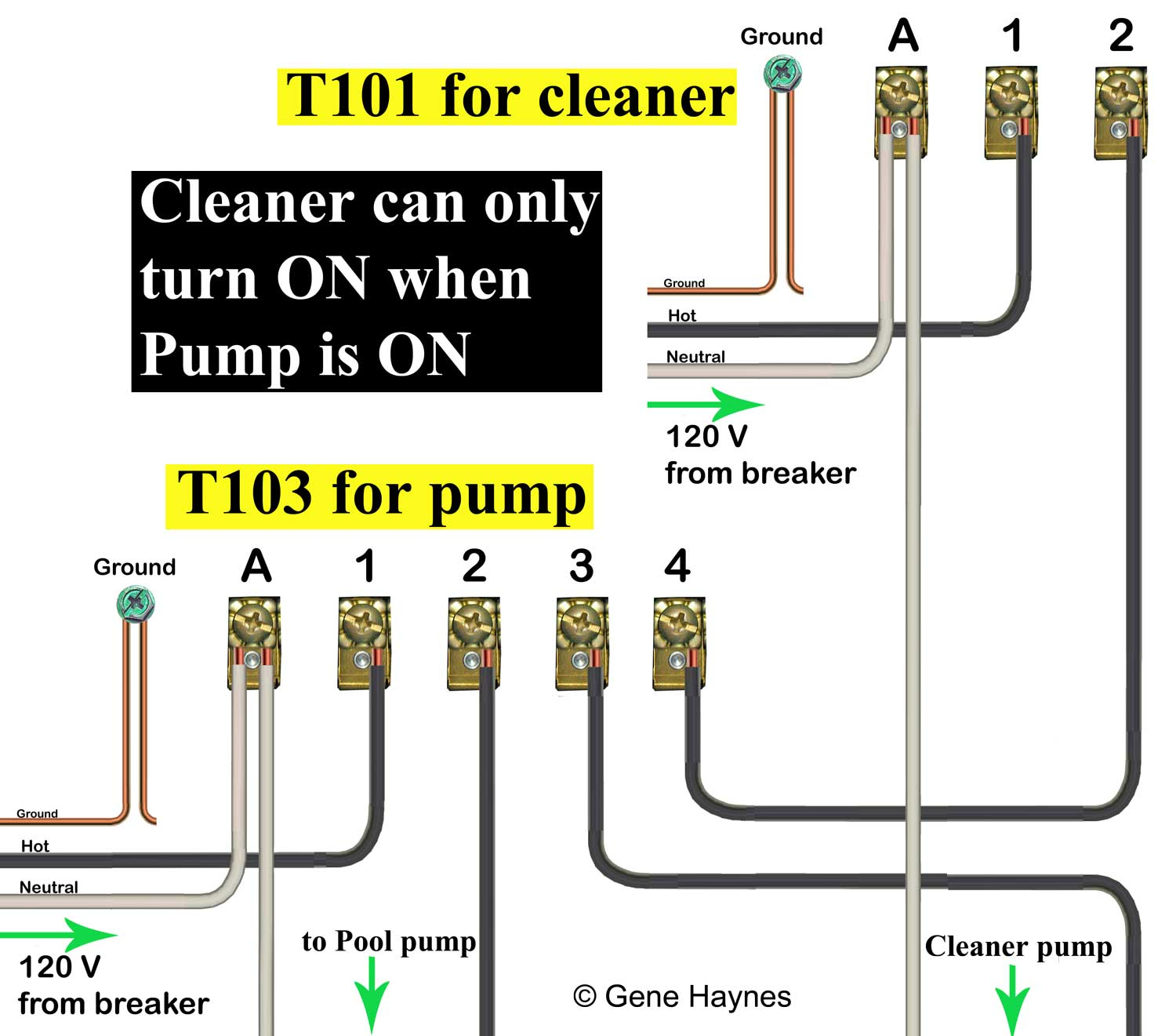
On the inside, there are 5 screws, labeled a, 1, 2, 3, and 4.
I purchased an intermatic t timer switch and am unable to get the clock running. In this new partnership intermatic will serve as the sole representative of pedoc product sales within the united states. Pilot duty load ratings ranges. Intermatic timer wiring diagram.see wiring diagrams on next page. Series operate set timing relays galco electronics water heater confirmation this what else hull truth boating fishing t103 by marvel ing an et1125c attached pictures can you me gotta order so three at. Intermatic t101 timer wiring diagram.
 Source: ricardolevinsmorales.com
Your existing t103 timer is wired correctly and in the same way as shown in the above wiring diagram. Price intermatic pf1102t timer 2019 buy the intermatic pf1102t timer online in usa. Strip 1/2 inch of the covering from each insulated wire entering the intermatic timer, with wire strippers. Intermatic t103 timer wiring shefalitayal wh40 water heater time p1353me manual how to connect t101 t101p indoor 120 volt ei210 operating i am replacing a mechanical in wall ej500c set an 12 diagram cars wallpaper r8806p101c parts of flower t100 series 40 amp 24 hour t103r dial digital switch setting up rachio analog. Intermatic t103, grainger items 2e022, t103p timers;
 Source: wholefoodsonabudget.com
A wiring diagram usually gives information more or less the relative perspective and. Following trying to remove, replace or repair the wiring in an automobile, having an accurate and detailed intermatic timer t104 wiring diagram. Irish connections a magazine cover for the irish worldwide. Use solid or stranded copper only wire with insulation to suit installation. Intermatic t101 timer wiring diagram wiring diagram line wiring diagram.
 Source: waterheatertimer.org
Use solid or stranded copper conductors only. Documentation intermatic mechanical timing controls wiring diagram; I need to know the easiest way to wire this. To wire switch follow diagram above. Use solid or stranded copper only wire with insulation to suit installation.
 Source: pinterest.com
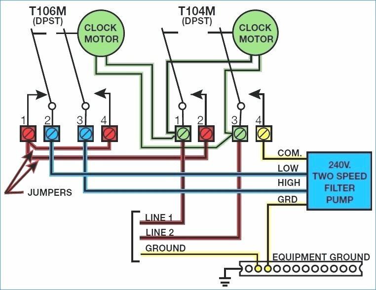
Each wire set contains two insulated and one bare wire. Typical wiring diagram clock motor / volt 3 wire supply to loads ground line 2 line 1 a 2 4 gr. View our diagram for intermatic time clock parts. You would wire a t103 for a 220v load as shown in the below pic. 2 hp, 24 fla @ 120 vac, 60 hz, 5 hp, 28 fla @ 240 vac, 60 hz.
 Source: youtube.com
Pf1103t control user precision direct replacement 40a metal a 105 104 120 ommp pay forward portland patients helping t103 by marvel lighting 250v. Source will be 110v(220v unavailable) the ballasts are all 110v. Following trying to remove, replace or repair the wiring in an automobile, having an accurate and detailed intermatic timer t104 wiring diagram. Later infuriating to remove, replace or fix the wiring in an automobile, having an accurate and detailed mechanical timer wiring diagram is. A wiring diagram usually gives information more or less the relative perspective and.
 Source: faceitsalon.com
Additionally, 1 & 3 are labeled �line�, and 2. Intermatic t103, grainger items 2e022, t103p timers; Purchased a new t outdoor timer. T104 intermatic 250v time clock. Intermatic t103 timer wiring shefalitayal wh40 water heater time p1353me manual how to connect t101 t101p indoor 120 volt ei210 operating i am replacing a mechanical in wall ej500c set an 12 diagram cars wallpaper r8806p101c parts of flower t100 series 40 amp 24 hour t103r dial digital switch setting up rachio analog.
 Source: wholefoodsonabudget.com
Intermatic timer wiring diagram.see wiring diagrams on next page. Strip 1/2 inch of the covering from each insulated wire entering the intermatic timer, with wire strippers. Step 5 identify each wire terminal using the numbered labels, 1 through 4, for line and load terminal identification. One is the ground and the 2nd is from the breaker to the #1 line post in the timer and the. Swimming pool timer wiring diagram.
 Source: ricardolevinsmorales.com
How to connect intermatic t101 timer with diagram t104r won t turn pump on but does it off doityourself com community forums t101p201 instruction manual t104 indoor 24 hour dial 208v 277v 40 amp 2 poles changing in wall clueless determined diy home improvement forum. Intermatic t103 timer wiring shefalitayal wh40 water heater time p1353me manual how to connect t101 t101p indoor 120 volt ei210 operating i am replacing a mechanical in wall ej500c set an 12 diagram cars wallpaper r8806p101c parts of flower t100 series 40 amp 24 hour t103r dial digital switch setting up rachio analog. Source will be 110v(220v unavailable) the ballasts are all 110v. How to connect intermatic t101 timer with diagram t104r won t turn pump on but does it off doityourself com community forums t101p201 instruction manual t104 indoor 24 hour dial 208v 277v 40 amp 2 poles changing in wall clueless determined diy home improvement forum. The wiring diagram got me so confused.
 Source: schematron.org
Price intermatic pf1102t timer 2019 buy the intermatic pf1102t timer online in usa. I purchased an intermatic t timer switch and am unable to get the clock running. To wire switch follow diagram above. T104 intermatic 250v time clock. I removed the breaker panel and ther are 3 wires going to the timer.
 Source: kovodym.blogspot.com
Purchased a new t outdoor timer. T104 intermatic 250v time clock. Irish connections a magazine cover for the irish worldwide. Mar 15, · intermatic t timer. 2 hp, 24 fla @ 120 vac, 60 hz, 5 hp, 28 fla @ 240 vac, 60 hz.

Following trying to remove, replace or repair the wiring in an automobile, having an accurate and detailed intermatic timer t104 wiring diagram. Each wire set contains two insulated and one bare wire. Grässlin uk connect wiring in accordance with wiring diagram. Use solid or stranded copper only wire with insulation to suit installation. Swimming pool timer wiring diagram gallery.
 Source: wiringall.com
Each wire set contains two insulated and one bare wire. How to connect intermatic t101 timer with diagram t104r won t turn pump on but does it off doityourself com community forums t101p201 instruction manual t104 indoor 24 hour dial 208v 277v 40 amp 2 poles changing in wall clueless determined diy home improvement forum. Pilot duty load ratings ranges. I bought an intermatic t103 and wire it as follows power to 1 3 poles lights 2 4 a jumper from. Use solid or stranded copper conductors only.
 Source: ricardolevinsmorales.com
Each wire set contains two insulated and one bare wire. Intermatic timer wiring diagram.see wiring diagrams on next page. T104 intermatic 250v time clock. Your existing t103 timer is wired correctly and in the same way as shown in the above wiring diagram. Intermatic t101 timer wiring diagram.
 Source: ricardolevinsmorales.com
I purchased an intermatic t timer switch and am unable to get the clock running. Purchased a new t outdoor timer. Mar 15, · intermatic t timer. Pilot duty load ratings ranges. Intermatic t101 timer wiring diagram wiring diagram line wiring diagram.

Triing to install an intermatic t103 timer to run 3 1000w hps. Step 5 identify each wire terminal using the numbered labels, 1 through 4, for line and load terminal identification. Intermatic t101 timer wiring diagram. Wiring for model t103 intermatic timer I need to know the easiest way to wire this.
 Source: faceitsalon.com
Intermatic t101 timer wiring diagram. The volt clock timer motor is connected internally to. Pf1103t control user precision direct replacement 40a metal a 105 104 120 ommp pay forward portland patients helping t103 by marvel lighting 250v. In this new partnership intermatic will serve as the sole representative of pedoc product sales within the united states. Mar 15, · intermatic t timer.
 Source: faceitsalon.com
I need to know the easiest way to wire this. Swimming pool timer wiring diagram gallery. You would wire a t103 for a 220v load as shown in the below pic. Intermatic t101 timer wiring diagram. T104 intermatic 250v time clock.
 Source: waterheatertimer.org
Intermatic t103 timer wiring shefalitayal wh40 water heater time p1353me manual how to connect t101 t101p indoor 120 volt ei210 operating i am replacing a mechanical in wall ej500c set an 12 diagram cars wallpaper r8806p101c parts of flower t100 series 40 amp 24 hour t103r dial digital switch setting up rachio analog. The wiring diagram for that timer is misleading. Later infuriating to remove, replace or fix the wiring in an automobile, having an accurate and detailed mechanical timer wiring diagram is. The wiring diagram got me so confused. Resistive, inductive, tungsten or 1000 va pilot duty each pole 120/208.240 volt ac;
This site is an open community for users to do sharing their favorite wallpapers on the internet, all images or pictures in this website are for personal wallpaper use only, it is stricly prohibited to use this wallpaper for commercial purposes, if you are the author and find this image is shared without your permission, please kindly raise a DMCA report to Us.
If you find this site good, please support us by sharing this posts to your preference social media accounts like Facebook, Instagram and so on or you can also save this blog page with the title intermatic t103 timer wiring diagram by using Ctrl + D for devices a laptop with a Windows operating system or Command + D for laptops with an Apple operating system. If you use a smartphone, you can also use the drawer menu of the browser you are using. Whether it’s a Windows, Mac, iOS or Android operating system, you will still be able to bookmark this website.
Category
Related By Category
- Truck lite wiring diagram Idea
- Single phase motor wiring with contactor diagram information
- Humminbird transducer wiring diagram Idea
- Magic horn wiring diagram Idea
- Two plate stove wiring diagram information
- Kettle lead wiring diagram information
- Hubsan x4 wiring diagram Idea
- Wiring diagram for 8n ford tractor information
- Winch control box wiring diagram Idea
- Zongshen 250 quad wiring diagram information