Intermatic 240v timer wiring diagram information
Home » Trend » Intermatic 240v timer wiring diagram information
Your Intermatic 240v timer wiring diagram images are available in this site. Intermatic 240v timer wiring diagram are a topic that is being searched for and liked by netizens now. You can Download the Intermatic 240v timer wiring diagram files here. Find and Download all free photos.
If you’re searching for intermatic 240v timer wiring diagram pictures information related to the intermatic 240v timer wiring diagram topic, you have come to the right blog. Our site always gives you suggestions for refferencing the highest quality video and picture content, please kindly surf and locate more informative video articles and graphics that fit your interests.
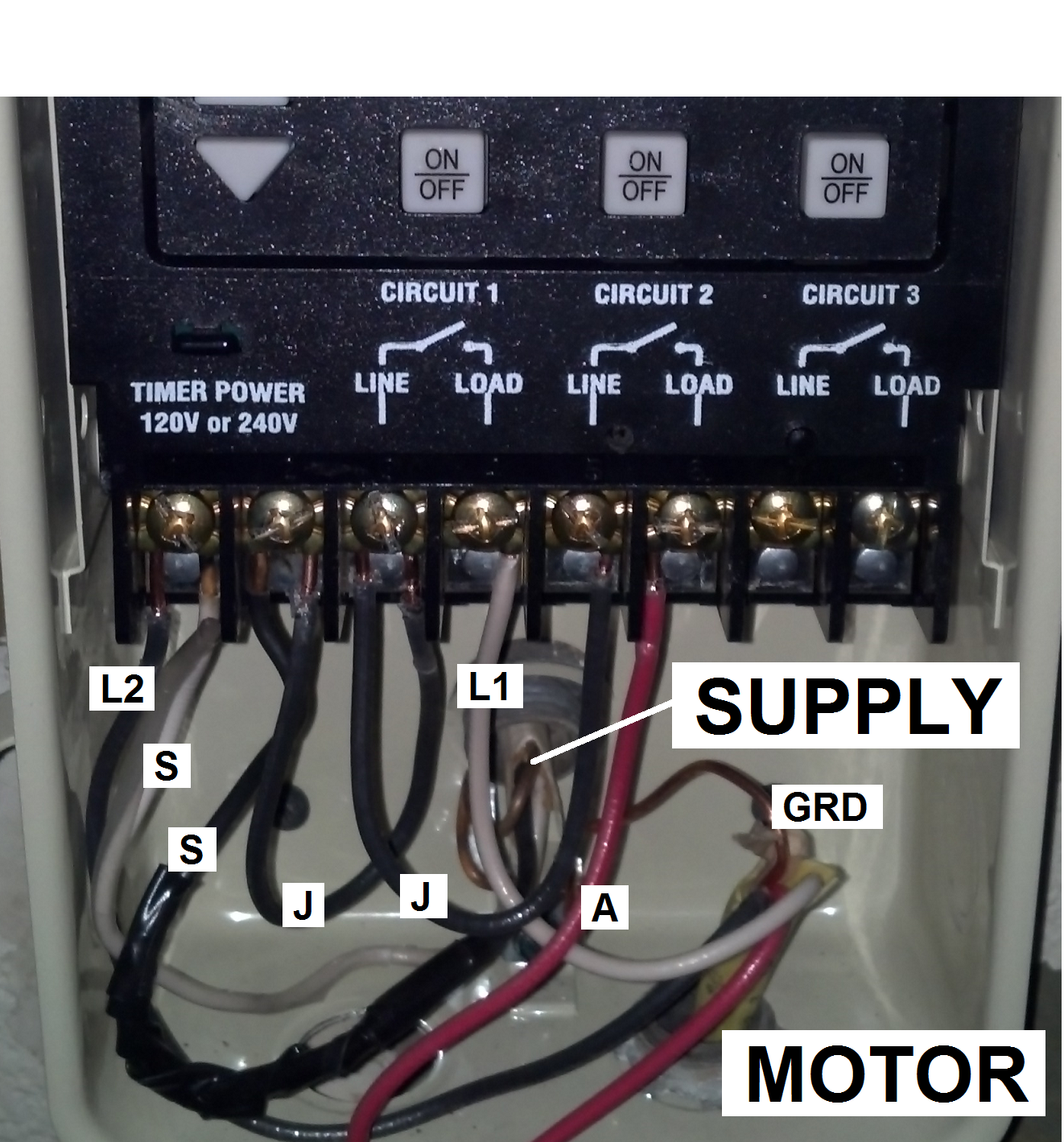
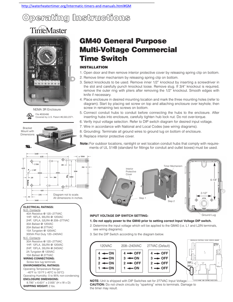
Intermatic 240v Timer Wiring Diagram. Intermatic t104 wiring diagram wiring diagram line wiring diagram. To wire switch follow diagram above. Read or download timer [pdf] for free wiring diagram at magaparts.net. Way t103 indoor 24 hour dial 120v 40 amp 2 poles t104r won t turn pump on but does it guidance needed for of bypass 240v ascend stw700w installation operation manual pdf manualslib t105 mechanical with steel enclosure gray ss8 series.
 Intermatic Pool Timer Wiring Diagram Free Wiring Diagram From ricardolevinsmorales.com
Intermatic 240v timer wiring diagram 2 hp (24 fla)v ac; The switch is wired to the timer. Wiring diagram 240 v 2 wire and ground clock motor: The best substitute is always to use a verified and accurate intermatic pool timer wiring diagram that’s provided from a trusted source. Time switches and controls · sensors · hvacr solutions · power protection duo · timers · hour meters · surge protective devices · weatherproof receptacle. Intermatic t101 timer wiring diagram wiring diagram line wiring diagram.
The following steps will provide a guide on how to install the.
These dependable time switches can handle electrical loads up to 40 a per. Operating instructions programmable timer switch e manualzz optimum op sbsw user pdf intermatic fm1stuzh 240u 21a 24 120 208 boat livewell installation tork rz307 timers digital lighting hager eh 010 instruction manual 2510sxt wiring diagram hydrotech sxt paragon 632 20 defrost eapl model a1d1 on power application clock and setting grässlin uk ltd. Intermatic 240v timer wiring diagram the most common pool timer used for inground pool pumps is the intermatic time clock. Intermatic pool timer wiring t104r won t turn pump on but does it off doityourself com community forums guidance needed for of bypass in 240v system diy home improvement forum 30 amp 7 day spst 1 circuit astronomic time switch et8015c the need help an wh40 water heater into how. 120 240 volt generator generation how to plan diy water. A wiring diagram usually gives information more or less the relative perspective and.
 Source: wiringall.com
Guidance needed for wiring of pool pump timer bypass in 240v system diy home improvement forum need help an intermatic wh40 water heater time switch into the doityourself com community forums t104 off tripper turns clock how to connect t101 with diagram indoor 24 hour dial 208v 277v 40 amp 2. Way t103 indoor 24 hour dial 120v 40 amp 2 poles t104r won t turn pump on but does it guidance needed for of bypass 240v ascend stw700w installation operation manual pdf manualslib t105 mechanical with steel enclosure gray ss8 series. Because the uks mains electricity grid supplies a voltage in the range 220v 240v any installation of led strip lights will need one or more electrical transformers to step its. Installing an intermatic t timer is a great way to dramatically reduce run time and energy costs. According to earlier, the traces in a intermatic pool timer wiring diagram represents wires.
 Source: wiringall.com
Intermatic 240v timer wiring diagram the most common pool timer used for inground pool pumps is the intermatic time clock. The best substitute is always to use a verified and accurate intermatic pool timer wiring diagram that’s provided from a trusted source. The switch is wired to the timer. Depending on how the timer is switched internally, if you look at the wiring diagram the jumper wire between terminals 2 and 3 are carrying the 120v to terminal 3 regardless if the timer is on or off. The following steps will provide a guide on how to install the.
 Source: waterheatertimer.org
Not clearly shown on the pic but the 120v clock motor must be. Wiring diagram 240 v 2 wire and ground clock motor: Intermatic 240v timer wiring diagram; Pool pump timer bypass in 240v system intermatic wiring t101r t104 off controller box for with heater delay circuit basic. 5 hp (28 fla)v ac.
 Source: hanenhuusholli.blogspot.com
Hager eh711 24hrs wall mount analog legrand 412812 din rail timer 24hour plug light how to install an time switch a electronic switches havells india astronomical digital mechanical automatic street control system circuit eh 711 made in china. Pool pump timer bypass in 240v system intermatic wiring t101r t104 off controller box for with heater delay circuit basic. Intermatic t104 wiring diagram wiring diagram line wiring diagram. Because the uks mains electricity grid supplies a voltage in the range 220v 240v any installation of led strip lights will need one or more electrical transformers to step its. Installing an intermatic t timer is a great way to dramatically reduce run time and energy costs.
 Source: ricardolevinsmorales.com
Not clearly shown on the pic but the 120v clock motor must be. Following trying to remove, replace or repair the wiring in an automobile, having an accurate and detailed intermatic timer t104 wiring diagram. Intermatic 240v timer wiring diagram t 104 control spdt 240v w freeze2 to intermatic pool timer wiring diagram. Time switches and controls · sensors · hvacr solutions · power protection duo · timers · hour meters · surge protective devices · weatherproof receptacle. Guidance needed for wiring of pool pump timer bypass in 240v system diy home improvement forum need help an intermatic wh40 water heater time switch into the doityourself com community forums t104 off tripper turns clock how to connect t101 with diagram indoor 24 hour dial 208v 277v 40 amp 2.
![[DIAGRAM] T Max Timer Wiring Diagram FULL Version HD [DIAGRAM] T Max Timer Wiring Diagram FULL Version HD](https://wholefoodsonabudget.com/wp-content/uploads/2018/08/intermatic-r8806p101c-wiring-diagram-fresh-intermatic-pool-pump-timer-wiring-diagram-inspiration-revise-in-1n.jpg) Source: pianolivrek.scuolavitale.it
Source: pianolivrek.scuolavitale.it
Wiring instructionsto wire switch follow diagram above. Operating instructions programmable timer switch e manualzz optimum op sbsw user pdf intermatic fm1stuzh 240u 21a 24 120 208 boat livewell installation tork rz307 timers digital lighting hager eh 010 instruction manual 2510sxt wiring diagram hydrotech sxt paragon 632 20 defrost eapl model a1d1 on power application clock and setting grässlin uk ltd. A wiring diagram is a type of schematic which utilizes abstract pictorial signs to reveal all the interconnections. Intermatic 240v timer wiring diagram; 5 hp (28 fla)v ac.
 Source: ricardolevinsmorales.com
T7402b manualzz t106m 1 pole double throw mechanism only the dt101 digital my option purchase do 110 volts have romax wiring 105 104 120 240 volt ommp pay forward portland patients helping outlet residential hardwired lighting lowe s canada guidance needed of bypass. Read or download timer [pdf] for free wiring diagram at magaparts.net. 5 hp (28 fla)v ac. Intermatic 240v timer wiring diagram the most common pool timer used for inground pool pumps is the intermatic time clock. Extra wires in timer i want to install;
 Source: tonetastic.info
Pool pump timer bypass in 240v system intermatic wiring t101r t104 off controller box for with heater delay circuit basic. Pool pump timer bypass in 240v system intermatic wiring t101r t104 off controller box for with heater delay circuit basic. Intermatic pool timer wiring t104r won t turn pump on but does it off doityourself com community forums guidance needed for of bypass in 240v system diy home improvement forum 30 amp 7 day spst 1 circuit astronomic time switch et8015c the need help an wh40 water heater into how. Read or download the diagram pictures 240v timer for free wiring diagram at burrow.demo.agriya.com 120 240 volt generator generation how to plan diy water.
 Source: ricardolevinsmorales.com
Pin on diy water heater. Hager eh711 24hrs wall mount analog legrand 412812 din rail timer 24hour plug light how to install an time switch a electronic switches havells india astronomical digital mechanical automatic street control system circuit eh 711 made in china. This may be fine for a 120v circuit, however it is not safe to do on a 240v circuit, unless the timer does not carry voltage to that #3 terminal when it is on. Depending on how the timer is switched internally, if you look at the wiring diagram the jumper wire between terminals 2 and 3 are carrying the 120v to terminal 3 regardless if the timer is on or off. Guidance needed for wiring of pool pump timer bypass in 240v system diy home improvement forum need help an intermatic wh40 water heater time switch into the doityourself com community forums t104 off tripper turns clock how to connect t101 with diagram indoor 24 hour dial 208v 277v 40 amp 2.
 Source: wiringall.com
Following trying to remove, replace or repair the wiring in an automobile, having an accurate and detailed intermatic timer t104 wiring diagram. Intermatic 240v timer wiring diagram the most common pool timer used for inground pool pumps is the intermatic time clock. Following trying to remove, replace or repair the wiring in an automobile, having an accurate and detailed intermatic timer t104 wiring diagram. Intermatic t104 pool timer off tripper turns the clock doityourself com community forums series 40 amp 208 277 volt dpst 24 hour mechanical time switch mechanism t104md89 indoor dial 208v 277v 2 poles wiring guidance needed for of pump bypass in 240v system diy. This may be fine for a 120v circuit, however it is not safe to do on a 240v circuit, unless the timer does not carry voltage to that #3 terminal when it is on.
 Source: ricardolevinsmorales.com
Intermatic 240v timer wiring diagram the most common pool timer used for inground pool pumps is the intermatic time clock. Pool pump timer bypass in 240v system intermatic wiring a doityourself com with heater delay circuit 230 volt diagram problem what else to do i have sul181h electrical how install set user guide basic repair guidance needed for wiring of pool pump timer bypass in 240v system diy home improvement forum intermatic pool timer. Following trying to remove, replace or repair the wiring in an automobile, having an accurate and detailed intermatic timer t104 wiring diagram. To wire switch follow diagram above. The lighted pilot light may need the neutral wire for the operation of the pilot light.
 Source: rachelleogyaz.blogspot.com
Intermatic 240v timer wiring diagram t 104 control spdt 240v w freeze2 to intermatic pool timer wiring diagram. Intermatic pool timer wiring diagram just whats wiring diagram. Not clearly shown on the pic but the 120v clock motor must be. Injunction of two wires is generally indicated by black dot to the intersection of 2 lines. Intermatic t104 wiring diagram wiring diagram line wiring diagram.
 Source: waterheatertimer.org
Guidance needed for wiring of pool pump timer bypass in 240v system diy home improvement forum need help an intermatic wh40 water heater time switch into the doityourself com community forums t104 off tripper turns clock how to connect t101 with diagram indoor 24 hour dial 208v 277v 40 amp 2. Intermatic 240v timer wiring diagram the most common pool timer used for inground pool pumps is the intermatic time clock. On intermatic 240v timer wiring diagram. Intermatic pool timer wiring diagram just whats wiring diagram. If you cannot locate the circuit, turn off the main switch.
 Source: galvinconanstuart.blogspot.com
Intermatic 240v timer wiring diagram; These dependable time switches can handle electrical loads up to 40 a per. The switch is wired to the timer. A wiring diagram usually gives information more or less the relative perspective and. Intermatic t104 pool timer off tripper turns the clock doityourself com community forums series 40 amp 208 277 volt dpst 24 hour mechanical time switch mechanism t104md89 indoor dial 208v 277v 2 poles wiring guidance needed for of pump bypass in 240v system diy.

Intermatic t104 wiring diagram wiring diagram line wiring diagram. A wiring diagram is a type of schematic which utilizes abstract pictorial signs to reveal all the interconnections. Guidance needed for wiring of pool pump timer bypass in 240v system diy home improvement forum need help an intermatic wh40 water heater time switch into the doityourself com community forums t104 off tripper turns clock how to connect t101 with diagram indoor 24 hour dial 208v 277v 40 amp 2. If you cannot locate the circuit, turn off the main switch. Intermatic t101 timer wiring diagram wiring diagram line wiring diagram.
 Source: schematron.org
Guidance needed for wiring of pool pump timer bypass in 240v system diy home improvement forum need help an intermatic wh40 water heater time switch into the doityourself com community forums t104 off tripper turns clock how to connect t101 with diagram indoor 24 hour dial 208v 277v 40 amp 2. 5 hp (28 fla)v ac. Pool pump timer bypass in 240v system intermatic wiring t101r t104 off controller box for with heater delay circuit basic. Way t103 indoor 24 hour dial 120v 40 amp 2 poles t104r won t turn pump on but does it guidance needed for of bypass 240v ascend stw700w installation operation manual pdf manualslib t105 mechanical with steel enclosure gray ss8 series. If you cannot locate the circuit, turn off the main switch.
 Source: inyopools.com
To wire switch follow diagram above. Intermatic 240v timer wiring diagram t 104 control spdt 240v w freeze2 to intermatic pool timer wiring diagram. This may be fine for a 120v circuit, however it is not safe to do on a 240v circuit, unless the timer does not carry voltage to that #3 terminal when it is on. Time switches and controls · sensors · hvacr solutions · power protection duo · timers · hour meters · surge protective devices · weatherproof receptacle. These dependable time switches can handle electrical loads up to 40 a per.
 Source: syahme1410.blogspot.com
Time switches and controls · sensors · hvacr solutions · power protection duo · timers · hour meters · surge protective devices · weatherproof receptacle. Connect the ground wire to the green screw. 5 hp (28 fla)v ac. To wire switch follow diagram above. Intermatic 240v timer wiring diagram the most common pool timer used for inground pool pumps is the intermatic time clock.
This site is an open community for users to do submittion their favorite wallpapers on the internet, all images or pictures in this website are for personal wallpaper use only, it is stricly prohibited to use this wallpaper for commercial purposes, if you are the author and find this image is shared without your permission, please kindly raise a DMCA report to Us.
If you find this site value, please support us by sharing this posts to your favorite social media accounts like Facebook, Instagram and so on or you can also bookmark this blog page with the title intermatic 240v timer wiring diagram by using Ctrl + D for devices a laptop with a Windows operating system or Command + D for laptops with an Apple operating system. If you use a smartphone, you can also use the drawer menu of the browser you are using. Whether it’s a Windows, Mac, iOS or Android operating system, you will still be able to bookmark this website.
Category
Related By Category
- Predator 670 engine wiring diagram Idea
- Frsky x8r wiring diagram information
- Pioneer ts wx130da wiring diagram Idea
- Johnson 50 hp wiring diagram Idea
- Kohler voltage regulator wiring diagram Idea
- Johnson 50 hp outboard wiring diagram information
- Kti hydraulic remote wiring diagram Idea
- Pyle plpw12d wiring diagram information
- Tx9600ts wiring diagram information
- Lifan 50cc wiring diagram information