Interconnected smoke alarms wiring diagram uk information
Home » Trending » Interconnected smoke alarms wiring diagram uk information
Your Interconnected smoke alarms wiring diagram uk images are available in this site. Interconnected smoke alarms wiring diagram uk are a topic that is being searched for and liked by netizens today. You can Find and Download the Interconnected smoke alarms wiring diagram uk files here. Download all free photos and vectors.
If you’re looking for interconnected smoke alarms wiring diagram uk images information related to the interconnected smoke alarms wiring diagram uk interest, you have pay a visit to the ideal site. Our website frequently provides you with hints for seeing the highest quality video and picture content, please kindly hunt and find more informative video content and graphics that fit your interests.
Interconnected Smoke Alarms Wiring Diagram Uk. How and where to install it, how to wire it and interconnect with another smo. Overall, 88% of all households had at least one working smoke alarm in their home, 11% of households either did When strobe lights and alarms are interconnected, all the interconnected devices must be powered from the same circuit. This video teaches you how to wire and interconnect smoke detectors.
 Hard Wired Smoke Detector Wiring Diagrams Wiring Diagram From tops-stars.com
The alarms do not have an earth terminal. Each smoke detector is supplied power from the 120v power line via the black and white wires. With a sloping or peaked ceiling install a smoke alarm within 600mm of the peak or a heat alarm within 150mm of the peak (measured vertically). Interconnecting smoke alarms how interconnected alarms function • interconnecting smoke alarms is a method of joining a series of alarms so that if any one alarm senses smoke, all the connected alarms will operate (alarm). Simple wiring diagrams for mains powered fire and carbon monoxide alarms. • a 9 v signal is applied to the interconnect wire (referenced to neutral) to alarm all the other interconnected alarms.
How to install a hardwired smoke alarm.
Vac power is provided by the hot (black) and neutral (white) wires. With a sloping or peaked ceiling install a smoke alarm within 600mm of the peak or a heat alarm within 150mm of the peak (measured vertically). Overall, 88% of all households had at least one working smoke alarm in their home, 11% of households either did In our basic wiring diagram a single or multiple heat and smoke detectors are installed in the home by connecting the live line or hot neutral ground and an interconnected wire to the alarm. First time wiring smoke and heat alarms into a flat. However, not all of these alarms were working at the time of the survey.
 Source: sfpow.blogspot.com
For details on how to do this, see connecting 4 wire smoke detectors. This video teaches you how to wire and interconnect smoke detectors. As its interconnected there is more than one but they were all done like this one. This will link all other smart rf alarms or accessories to communicate to hardwire interconnected alarms. When strobe lights and alarms are interconnected, all the interconnected devices must be powered from the same circuit.
 Source: hidupkudibumiini.blogspot.com
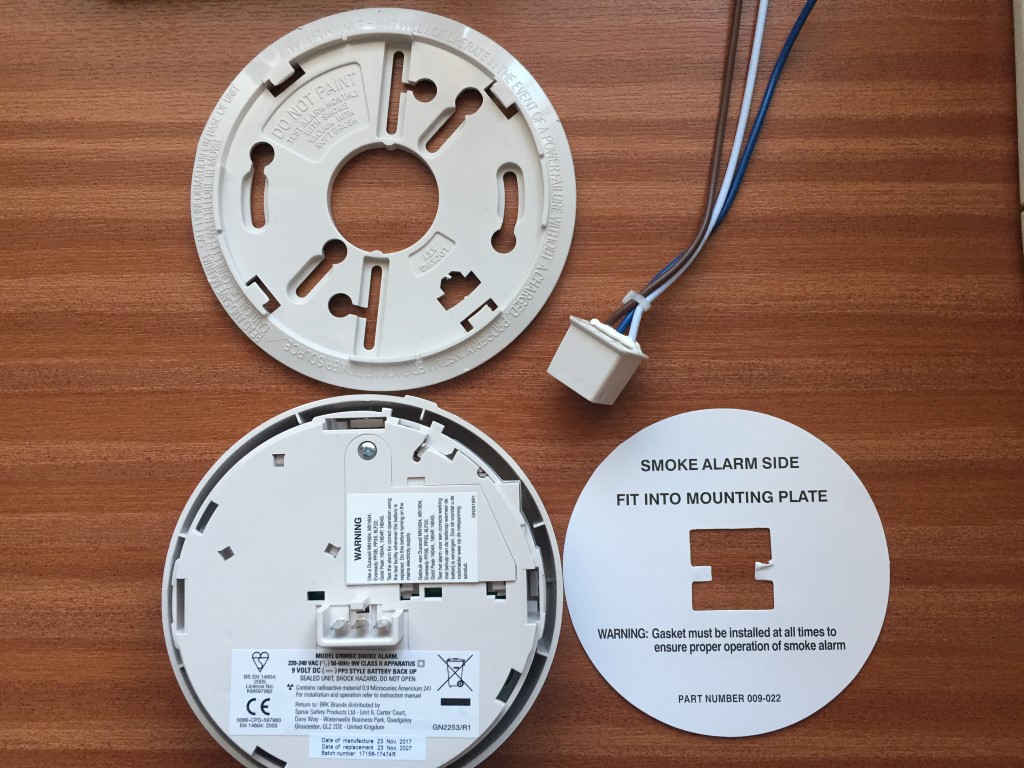
Remove the power connector from the new alarm’s packaging. Basic wiring diagrams and tips for installing aico smoke and co alarms. How to install a hardwired smoke alarm. Any red wires should be connected to the interconnect wire with the smoke detector, which is usually a yellow wire and should be listed in the manufacturer’s manual. On interlinked smoke alarm wiring diagram.
 Source: mswee3.blogspot.com
Wiring for hard wired alarms with radiolink interconnect. This video teaches you how to wire and interconnect smoke detectors. Am intending to connect the black to the line. Wiring for hard wired alarms with radiolink interconnect. Once the electrical wires have been attached, you can strip the ground wire and connect it.
 Source: schematron.org
How to install an interconnected mains operated smoke alarm. However, not all of these alarms were working at the time of the survey. This video teaches you how to wire and interconnect smoke detectors. • a 9 v signal is applied to the interconnect wire (referenced to neutral) to alarm all the other interconnected alarms. In our basic wiring diagram a single or multiple heat and smoke detectors are installed in the home by connecting the live line or hot neutral ground and an interconnected wire to the alarm.

Any red wires should be connected to the interconnect wire with the smoke detector, which is usually a yellow wire and should be listed in the manufacturer’s manual. A smoke or heat detector can be installed to the existing or new home wiring. To begin, turn off power at the junction box and connect the alarm to the building’s electrical wiring. This is the basic fire alarm system used in household wiring. In our basic wiring diagram, a single or multiple heat and smoke detectors are installed in the home by connecting the live (line or hot), neutral, ground and an interconnected wire to the alarm.
 Source: wiringdiagram.2bitboer.com
This is the basic fire alarm system used in household wiring. To begin, turn off power at the junction box and connect the alarm to the building’s electrical wiring. However, not all of these alarms were working at the time of the survey. When strobe lights and alarms are interconnected, all the interconnected devices must be powered from the same circuit. Wiring diagrams are included in the instructions supplied with all alarms, but here are a few basics.
 Source: wiringdiagram.2bitboer.com
In our basic wiring diagram, a single or multiple heat and smoke detectors are installed in the home by connecting the live (line or hot), neutral, ground and an interconnected wire to the alarm. To begin, turn off power at the junction box and connect the alarm to the building’s electrical wiring. This will link all other smart rf alarms or accessories to communicate to hardwire interconnected alarms. In our basic wiring diagram a single or multiple heat and smoke detectors are installed in the home by connecting the live line or hot neutral ground and an interconnected wire to the alarm. If your alarm is not a sealed back‑up battery alarm, then install the batteries following the steps within the manual.
 Source: wiringdiagram.2bitboer.com
Vac power is provided by the hot (black) and neutral (white) wires. To begin, turn off power at the junction box and connect the alarm to the building’s electrical wiring. Wiring for hard wired alarms with radiolink interconnect. This will link all other smart rf alarms or accessories to communicate to hardwire interconnected alarms. If your alarm is not a sealed back‑up battery alarm, then install the batteries following the steps within the manual.
 Source: mainetreasurechest.com
Separate hardwire interconnected networks in the dwelling. In our basic wiring diagram a single or multiple heat and smoke detectors are installed in the home by connecting the live line or hot neutral ground and an interconnected wire to the alarm. Assortment of duct smoke detector wiring diagram. As the battery is a back up for when the power fails. With a sloping or peaked ceiling install a smoke alarm within 600mm of the peak or a heat alarm within 150mm of the peak (measured vertically).
 Source: wiringdiagram.2bitboer.com
Overall, 88% of all households had at least one working smoke alarm in their home, 11% of households either did This will link all other smart rf alarms or accessories to communicate to hardwire interconnected alarms. How to install a hardwired smoke alarm. How to install an interconnected mains operated smoke alarm. Separate hardwire interconnected networks in the dwelling.
 Source: tops-stars.com
Each smoke detector is supplied power from the 120v power line via the black and white wires. A hardwired smoke alarm installation involves wiring one of the smoke detectors (closest to the voltage source) to a 120 vac breaker in the main electric panel or tapping from a 120 v electrical box, wiring it using a 14/2 cable with a black (live), a white (neutral), and a ground wire, as shown by the diagram in figure 5. For details on connecting smoke detectors and other devices to a typical alarm panel, see ademco vista 20p wiring diagram. All homes need smoke detectors, you must also wire your smoke detector on the same circu. How and where to install it, how to wire it and interconnect with another smo.
 Source: schematicandwiringdiagram.blogspot.com
This wiring plan was suggested as it would avoid using the earth for the interconnection wire, and therefore potentially confusing anyone else examining the wiring. How to install an interconnected mains operated smoke alarm. The alarms do not have an earth terminal. This wiring plan was suggested as it would avoid using the earth for the interconnection wire, and therefore potentially confusing anyone else examining the wiring. Remove the power connector from the new alarm’s packaging.
 Source: tops-stars.com
As its interconnected there is more than one but they were all done like this one. • a 9 v signal is applied to the interconnect wire (referenced to neutral) to alarm all the other interconnected alarms. How to install an interconnected mains operated smoke alarm. Simple wiring diagrams for mains powered fire and carbon monoxide alarms. This wiring plan was suggested as it would avoid using the earth for the interconnection wire, and therefore potentially confusing anyone else examining the wiring.
 Source: pinterest.com
Basic wiring diagrams and tips for installing aico smoke and co alarms. First time wiring smoke and heat alarms into a flat. This is the basic fire alarm system used in household wiring. In our basic wiring diagram, a single or multiple heat and smoke detectors are installed in the home by connecting the live (line or hot), neutral, ground and an interconnected wire to the alarm. However, not all of these alarms were working at the time of the survey.
 Source: wiringdiagram.2bitboer.com
Basic wiring diagrams and tips for installing aico smoke and co alarms. On interlinked smoke alarm wiring diagram. Find the home�s junction box and turn off power. The alarms do not have an earth terminal. Line up the alarm with the base plate and gently apply pressure until the alarm clicks into place.
 Source: smarts4k.com
Each smoke detector is supplied power from the 120v power line via the black and white wires. This will link all other smart rf alarms or accessories to communicate to hardwire interconnected alarms. The extra run of 4 conductor wire gives us a return path to the panel. This video teaches you how to wire and interconnect smoke detectors. As its interconnected there is more than one but they were all done like this one.
 Source: brk.co.uk
When strobe lights and alarms are interconnected, all the interconnected devices must be powered from the same circuit. • a 9 v signal is applied to the interconnect wire (referenced to neutral) to alarm all the other interconnected alarms. This is obviously the means by which they communicate with each other, and i decided to. This is the basic fire alarm system used in household wiring. To begin, turn off power at the junction box and connect the alarm to the building’s electrical wiring.
 Source: diagramweb.net
All homes need smoke detectors, you must also wire your smoke detector on the same circu. How and where to install it, how to wire it and interconnect with another smo. When strobe lights and alarms are interconnected, all the interconnected devices must be powered from the same circuit. Am intending to connect the black to the line. A maximum of 24 kidde safety devices may be interconnected in a multiple station arrangement.
This site is an open community for users to do submittion their favorite wallpapers on the internet, all images or pictures in this website are for personal wallpaper use only, it is stricly prohibited to use this wallpaper for commercial purposes, if you are the author and find this image is shared without your permission, please kindly raise a DMCA report to Us.
If you find this site adventageous, please support us by sharing this posts to your preference social media accounts like Facebook, Instagram and so on or you can also bookmark this blog page with the title interconnected smoke alarms wiring diagram uk by using Ctrl + D for devices a laptop with a Windows operating system or Command + D for laptops with an Apple operating system. If you use a smartphone, you can also use the drawer menu of the browser you are using. Whether it’s a Windows, Mac, iOS or Android operating system, you will still be able to bookmark this website.
Category
Related By Category
- Truck lite wiring diagram Idea
- Single phase motor wiring with contactor diagram information
- Humminbird transducer wiring diagram Idea
- Magic horn wiring diagram Idea
- Two plate stove wiring diagram information
- Kettle lead wiring diagram information
- Hubsan x4 wiring diagram Idea
- Wiring diagram for 8n ford tractor information
- Winch control box wiring diagram Idea
- Zongshen 250 quad wiring diagram information