Input module wiring diagram Idea
Home » Trend » Input module wiring diagram Idea
Your Input module wiring diagram images are ready in this website. Input module wiring diagram are a topic that is being searched for and liked by netizens today. You can Get the Input module wiring diagram files here. Get all royalty-free photos and vectors.
If you’re looking for input module wiring diagram images information related to the input module wiring diagram interest, you have come to the right blog. Our website always provides you with suggestions for viewing the maximum quality video and picture content, please kindly surf and locate more enlightening video articles and graphics that fit your interests.
Input Module Wiring Diagram. Siemens analog input module wiring diagram wiring diagram line wiring diagram wiring diagram line we are make source the schematics, wiring diagrams and technical photos Connect individual input wiring to numbered terminals on the 0…15 row (a) as indicated in the following table on the next page. Exposing less wire may result in a faulty connection. Slide the module into the chassis until the bottom tabs lock into place.
 SIEMENS ANALOG INPUT MODULE WIRING DIAGRAM Auto From electrowiring.herokuapp.com
For more information on front connector wiring and creating cable shields, for example, refer Hope this helps, daniel chartier Ge fanuc analog cur input block diagram ic693alg221 222 223 390 391 392 442 ic693alg392 wiring online ge fanuc emerson series 90 30. In this article, we are sharing the basic concepts of plc and dcs control systems wiring diagrams for digital input (di), digital output (do), analog input (ai), and analog output (ao) signals. Connect individual input wiring to numbered terminals on the 0…15 row (a) as indicated in the following table on the next page. The module is designed for class a circuit operation.
Analog input output module ai wiring diagrams of plc and dcs systems programming signals techniques 4 20ma 10v for how to read a diagram rslogix 5000 500 circuits inputs i o modules cara penyambungan sensor pada connection plcs net control loop.
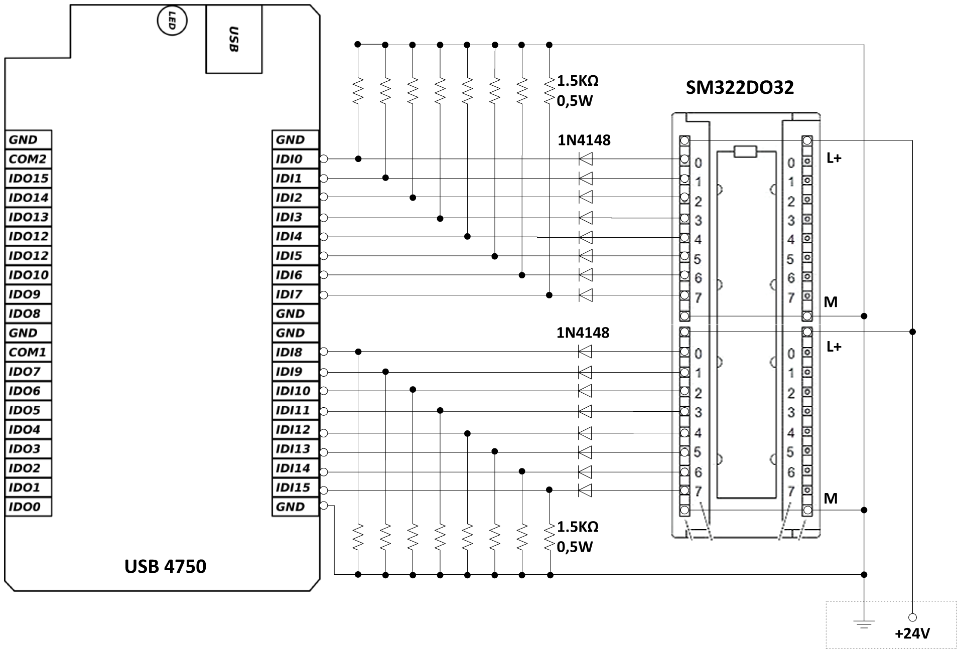
Bmxddi3202k main range of product modicon x80 product or component type discrete input module discrete input number 32 discrete input type isolated. By lucas swansen | february 20, 2019. For more information on front connector wiring and creating cable shields, for example, refer The switch is monitored by a plc digital input module. Looking at these modules we notice they have 16 channels available with similar wiring schemes. Ge fanuc analog cur input block diagram ic693alg221 222 223 390 391 392 442 ic693alg392 wiring online ge fanuc emerson series 90 30.
 Source: manualsdir.com
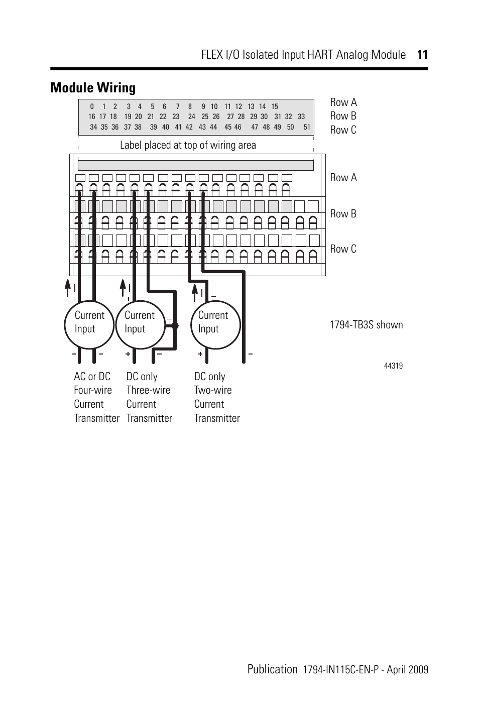
How do i wire the bmxddo3202k discrete io 24 vdc positive. Plc digital signals wiring techniques. Ge fanuc analog cur input block diagram ic693alg221 222 223 390 391 392 442 ic693alg392 wiring online ge fanuc emerson series 90 30. The flex™ i/o 8 channel universal isolated analog inputs module has fully isolated, universal, analog capability for noisy environments. In above figure, a level switch is mounted to a vessel.
 Source: datexel.com
Installation and wiring guidelines chapter 2 input module addressing, configuration and status information chapter 3 output module addressing, configuration and status information chapter 4. Wiring diagram and schematics this place is a growing library of the schematics, wiring diagrams and technical photos. In this documentation, step 7 is used as a synonym for all versions of the The m721 dual input, single relay output module, as well as providing two supervised inputs also provides a single change over relay output rated at 2a @30vdc. The circuit is powered through a circuit breaker (cb2) in an instrument power panel.
 Source: electrowiring.herokuapp.com
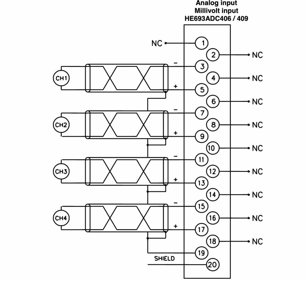
(about 6 mm) from the ends of all wires that connect to the terminal block of the module. (about 6 mm) from the ends of all wires that connect to the terminal block of the module. Looking at these modules we notice they have 16 channels available with similar wiring schemes. Each input can be configured as a current or voltage input with internal jumpers. 8 analog inputs voltage measuring type can be set per channel current measuring type can be set per channel measuring type resistance adjustable for channel 0, 2, 4 and 6
 Source: factoryio.com
In above figure, a level switch is mounted to a vessel. Wires as shown in the diagram. Fanuc input output module wiring diagram. Slide the module into the chassis until the bottom tabs lock into place. Wiring potentiometer to analog input output module ai 4xu i rtd tc aq 2xu entries forum industry support siemens.
 Source: pdfsupply.com
Analog input output module ai wiring diagrams of plc and dcs systems programming signals techniques 4 20ma 10v for how to read a diagram rslogix 5000 500 circuits inputs i o modules cara penyambungan sensor pada connection plcs net control loop. In this documentation, step 7 is used as a synonym for all versions of the (about 6 mm) from the ends of all wires that connect to the terminal block of the module. The flex™ i/o 8 channel universal isolated analog inputs module has fully isolated, universal, analog capability for noisy environments. In this documentation, step 7 is used as a synonym for all versions of the
 Source: wiringdiagramall.blogspot.com
In this documentation, step 7 is used as a synonym for all versions of the The examples and diagrams in this manual ar e included solely for illustrative purposes. Looking at these modules we notice they have 16 channels available with similar wiring schemes. You can select from five voltage or three current input ranges. Slide the module into the chassis until the bottom tabs lock into place.
 Source: manualsdir.com
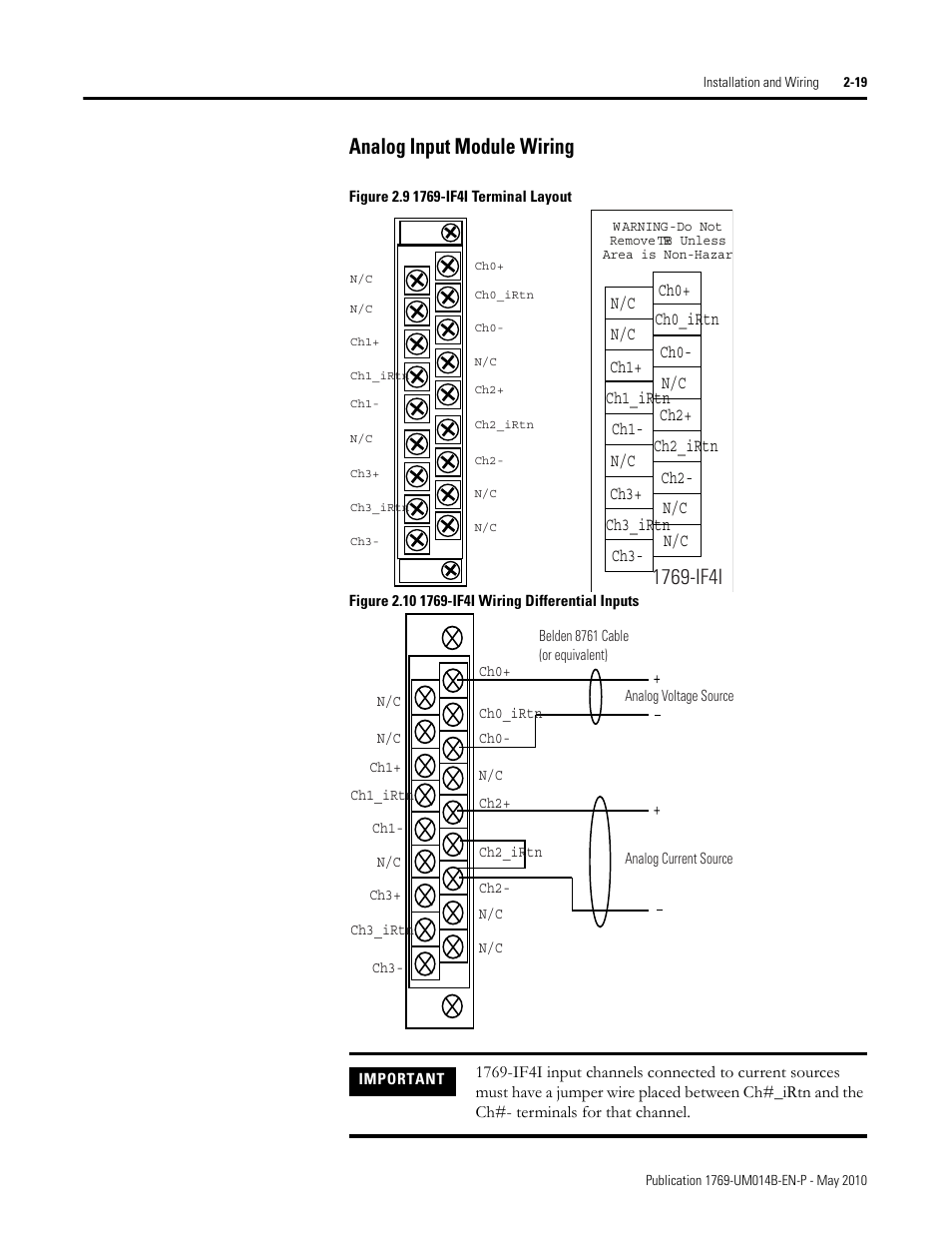
Connect individual input wiring to numbered terminals on the 0…15 row (a) as indicated in the following table on the next page. Installation and wiring guidelines chapter 2 input module addressing, configuration and status information chapter 3 output module addressing, configuration and status information chapter 4. Siemens analog input module wiring diagram wiring diagram and schematics. The module is designed for class a circuit operation. Siemens analog input module wiring diagram wiring diagram line wiring diagram wiring diagram line we are make source the schematics, wiring diagrams and technical photos
 Source: 14core.com
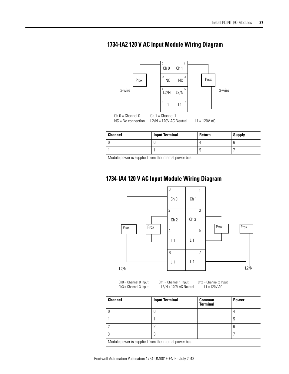
The switch is monitored by a plc digital input module. When stripping wire ends, exposing more wire may cause a ground fault; The examples and diagrams in this manual ar e included solely for illustrative purposes. Siemens analog input module wiring diagram wiring diagram line wiring diagram wiring diagram line we are make source the schematics, wiring diagrams and technical photos Wires as shown in the diagram.
 Source: manualsdir.com
Installation and wiring guidelines chapter 2 input module addressing, configuration and status information chapter 3 output module addressing, configuration and status information chapter 4. Siemens analog input module wiring diagram wiring diagram and schematics. In above figure, a level switch is mounted to a vessel. The flex™ i/o 8 channel universal isolated analog inputs module has fully isolated, universal, analog capability for noisy environments. The switch is monitored by a plc digital input module.
 Source: wiringdiagramall.blogspot.com
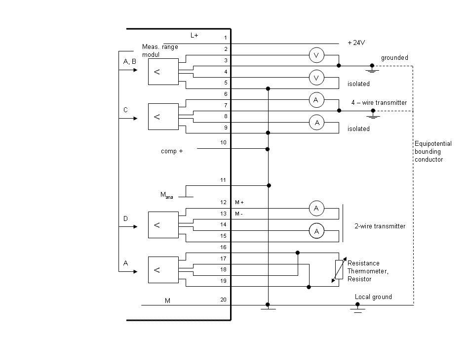
Ge fanuc analog cur input block diagram ic693alg221 222 223 390 391 392 442 ic693alg392 wiring online ge fanuc emerson series 90 30. In above figure, a level switch is mounted to a vessel. Use this diagram to identify the external features of the module. Route the wires down and away from the module, securing them with the wire tie. In this article, we are sharing the basic concepts of plc and dcs control systems wiring diagrams for digital input (di), digital output (do), analog input (ai), and analog output (ao) signals.
 Source: electrowiring.herokuapp.com
The switch is monitored by a plc digital input module. The wiring base assembly consists of one of the following: Wiring potentiometer to analog input output module ai 4xu i rtd tc aq 2xu entries forum industry support siemens. Ge fanuc analog cur input block diagram ic693alg221 222 223 390 391 392 442 ic693alg392 wiring online ge fanuc emerson series 90 30. (about 6 mm) from the ends of all wires that connect to the terminal block of the module.
 Source: profibus-connector.com
The wiring base assembly consists of one of the following: Wiring and block diagram has been modified. By lucas swansen | february 20, 2019. For more information on front connector wiring and creating cable shields, for example, refer Analog output module aq 4xu i st 6es7532 5hd00 0ab0 wiring potentiometer to input ai rtd tc 2xu entries forum industry support siemens profibus connector 6es7331 1kf02 s7 300 7kf02 modules s5 135u 155u user manual page 447 560 programming and configure inputs 4 20ma 1200 sm331 how connect a this forums mrplc com blog archive 6es7332 5hd01… read.
Source: electrowiring.herokuapp.com
Siemens analog input module wiring diagram wiring diagram line wiring diagram wiring diagram line we are make source the schematics, wiring diagrams and technical photos Plc digital signals wiring techniques. Siemens analog input module wiring diagram wiring diagram line wiring diagram wiring diagram line we are make source the schematics, wiring diagrams and technical photos Analog input output module ai wiring diagrams of plc and dcs systems programming signals techniques 4 20ma 10v for how to read a diagram rslogix 5000 500 circuits inputs i o modules cara penyambungan sensor pada connection plcs net control loop. How do i wire the bmxddo3202k discrete io 24 vdc positive.
 Source: datexel.com
Wiring potentiometer to analog input output module ai 4xu i rtd tc aq 2xu entries forum industry support siemens. Wiring and block diagram has been modified. Mix and match i/o modules. Analog input output module ai wiring diagrams of plc and dcs systems programming signals techniques 4 20ma 10v for how to read a diagram rslogix 5000 500 circuits inputs i o modules cara penyambungan sensor pada connection plcs net control loop. Slide the module into the chassis until the bottom tabs lock into place.
 Source: datexel.com
Wiring diagram and schematics this place is a growing library of the schematics, wiring diagrams and technical photos. Wiring potentiometer to analog input output module ai 4xu i rtd tc aq 2xu entries forum industry support siemens. Analog input output module ai wiring diagrams of plc and dcs systems programming signals techniques 4 20ma 10v for how to read a diagram rslogix 5000 500 circuits inputs i o modules cara penyambungan sensor pada connection plcs net control loop. By lucas swansen | february 20, 2019. Ge fanuc analog cur input block diagram ic693alg221 222 223 390 391 392 442 ic693alg392 wiring online ge fanuc emerson series 90 30.
 Source: electrowiring.herokuapp.com
How do i wire the bmxddo3202k discrete io 24 vdc positive. The main power feed is brought to a marshalling panel, where the power is split, feeding multiple fused circuits. 8 analog inputs voltage measuring type can be set per channel current measuring type can be set per channel measuring type resistance adjustable for channel 0, 2, 4 and 6 By lucas swansen | february 20, 2019. For more information on front connector wiring and creating cable shields, for example, refer
 Source: diagramweb.net
Both of the noted safety modules require. Exposing less wire may result in a faulty connection. You can select from five voltage or three current input ranges. Wiring diagram and schematics this place is a growing library of the schematics, wiring diagrams and technical photos. How do i wire the bmxddo3202k discrete io 24 vdc positive.
 Source: electrowiring.herokuapp.com
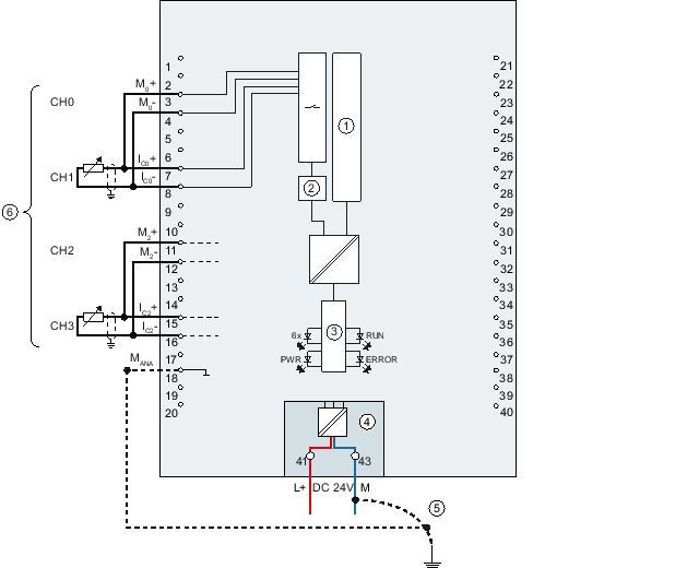
M721 dual input module with output the m700 series modules are designed for use with any notifier protocol fire alarm control panel and include selectable loop isolation in every device. Verify that all field wiring is free of opens, shorts, and ground faults. Siemens analog input module wiring diagram wiring diagram and schematics. 8 analog inputs voltage measuring type can be set per channel current measuring type can be set per channel measuring type resistance adjustable for channel 0, 2, 4 and 6 Ge fanuc analog cur input block diagram ic693alg221 222 223 390 391 392 442 ic693alg392 wiring online ge fanuc emerson series 90 30.
This site is an open community for users to submit their favorite wallpapers on the internet, all images or pictures in this website are for personal wallpaper use only, it is stricly prohibited to use this wallpaper for commercial purposes, if you are the author and find this image is shared without your permission, please kindly raise a DMCA report to Us.
If you find this site serviceableness, please support us by sharing this posts to your favorite social media accounts like Facebook, Instagram and so on or you can also save this blog page with the title input module wiring diagram by using Ctrl + D for devices a laptop with a Windows operating system or Command + D for laptops with an Apple operating system. If you use a smartphone, you can also use the drawer menu of the browser you are using. Whether it’s a Windows, Mac, iOS or Android operating system, you will still be able to bookmark this website.
Category
Related By Category
- Predator 670 engine wiring diagram Idea
- Frsky x8r wiring diagram information
- Pioneer ts wx130da wiring diagram Idea
- Johnson 50 hp wiring diagram Idea
- Kohler voltage regulator wiring diagram Idea
- Johnson 50 hp outboard wiring diagram information
- Kti hydraulic remote wiring diagram Idea
- Pyle plpw12d wiring diagram information
- Tx9600ts wiring diagram information
- Lifan 50cc wiring diagram information