Infrared motion sensor wiring diagram Idea
Home » Trend » Infrared motion sensor wiring diagram Idea
Your Infrared motion sensor wiring diagram images are ready in this website. Infrared motion sensor wiring diagram are a topic that is being searched for and liked by netizens today. You can Get the Infrared motion sensor wiring diagram files here. Download all free photos and vectors.
If you’re searching for infrared motion sensor wiring diagram pictures information linked to the infrared motion sensor wiring diagram topic, you have pay a visit to the right blog. Our site frequently provides you with suggestions for downloading the maximum quality video and picture content, please kindly surf and find more enlightening video articles and graphics that fit your interests.
Infrared Motion Sensor Wiring Diagram. E circuits youtube switch touch circuit. If parallel connection of multiple devices to control a common load is required, Brazix infrared motion sensor occupancy swivel switch mss4kw The pir sensor stands for passive infrared sensor.
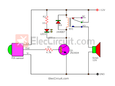 Motion detector alarm circuit with PIR sensor Simple and From eleccircuit.com
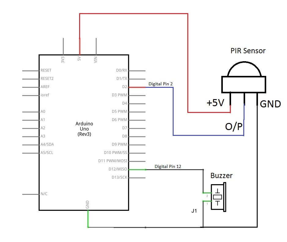
In the wiring diagram below, you can see how to hook it up to the arduino. Pin 1 is vcc which is connected positive 5v supply Wiring diagram will come with a number of easy to follow wiring diagram directions. Switch/circuit breaker then switch back on within one second. A wiring diagram is a simplified conventional pictorial depiction of an electrical circuit. Whenever the water level rises or decreases and comes in contact of any sensor then.
These state of the art devices use passive infrared ultrasonic or a combined multi sensing technology.
Alarm pir sensor wiring diagram. 12v pir motion sensor wiring diagram wiring diagram line wiring diagram. Switch/circuit breaker then switch back on within one second. And the infrared region of pir sensor is from 0 75um to 1000um. It includes guidelines and diagrams for various varieties of wiring techniques and other items like lights, home windows, and so forth. As stated previous the lines in a wiring a motion sensor light diagram signifies wires.
 Source: tcworks.org
C0ea51 ceiling motion sensor wiring diagram wiring resources. There are three ir regions on spectrum named as near infrared 0 75 3um mid infrared 3 6um and far infrared higher than 6um. Then you can draw power for your motion sensors from the pins labeled u1 and gnd on the bottom left of the device base. Photo diode is connected in reverse bias inverting end of lm358 pin 2 is connected to the variable resistor to adjust the sensitivity of the sensor. Alarm pir sensor wiring diagram.
 Source: pinterest.com
The passive infrared sensor consists of three pins as shown below. Passive infrared motion sensor motion sensor technology, the series indoor infrascan is the next generation of the constantly evolving family of clipsal pir sensing devices. Pdtoweb 110 220v outdoor led waterproof infrared pir motion sensor light with a detector hacks forum to porch an extension cord 12v movement autonics pr12 4dn inductive proximity mce32 220 240v eaton arrow hart ahawc dt 120w. But it does not imply connection between the cables. Motion sensor lampholder residential networking connected home.
 Source: annawiringdiagram.com
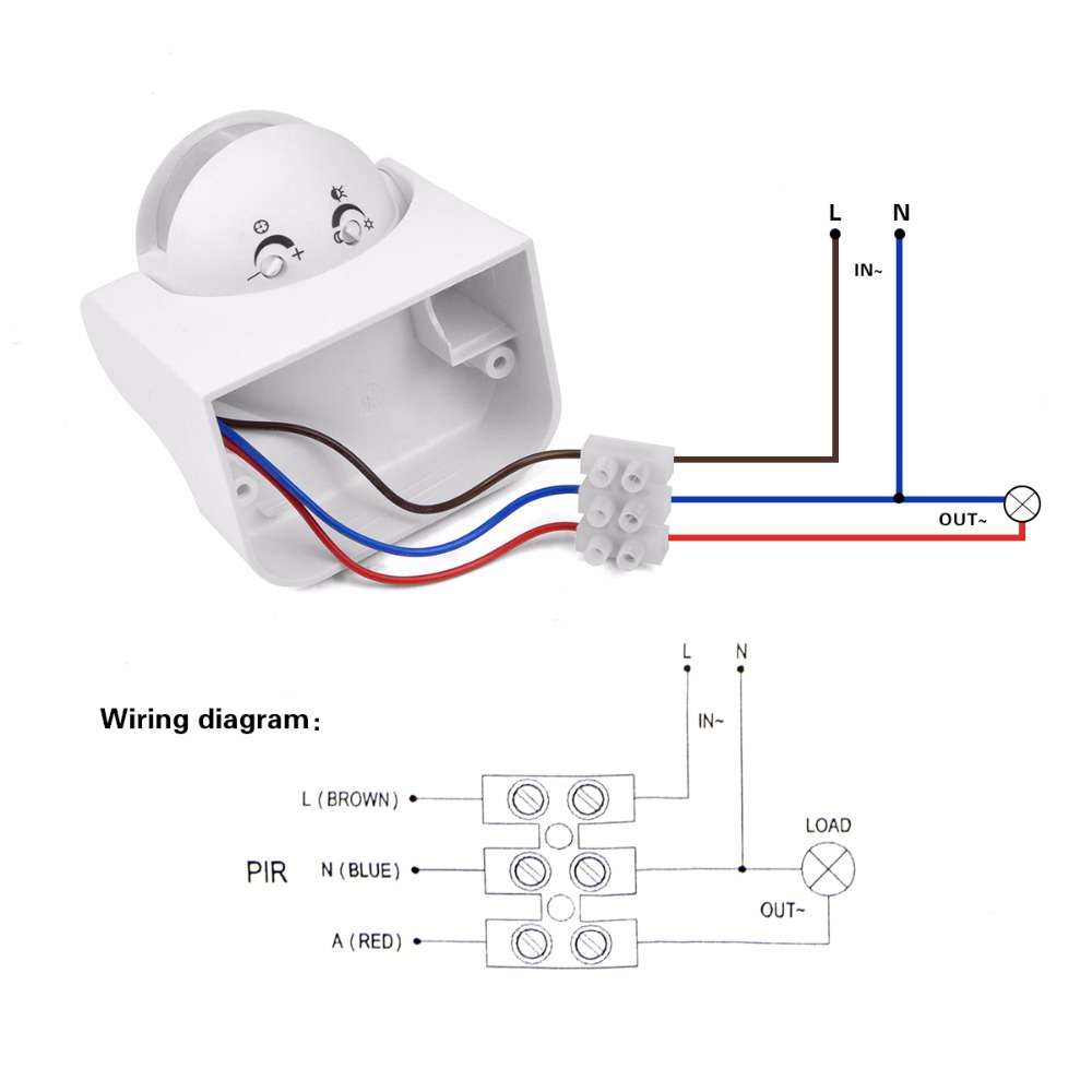
3 wire pir motion sensor wiring diagram. If not, the arrangement won’t function as it should be. And the infrared region of pir sensor is from 0 75um to 1000um. It includes guidelines and diagrams for various varieties of wiring techniques and other items like lights, home windows, and so forth. Pir sensor circuit and working with applications.
 Source: theorycircuit.com
Switch/circuit breaker then switch back on within one second. Multiple motion sensor wiring diagram. The pir sensor stands for passive infrared sensor. Switch/circuit breaker then switch back on within one second. Pir motion sensor light wiring diagram new wiring diagram for a pir motion sensor light wiring diagram.
 Source: pinterest.com
C0ea51 ceiling motion sensor wiring diagram wiring resources. Pir motion sensor light wiring diagram. E circuits youtube switch touch circuit. And the infrared region of pir sensor is from 0 75um to 1000um. 3 wire pir motion sensor wiring diagram.
 Source: easyelectronicsproject.com
Once you’ve connected the motion sensor power wires, connect the signal wires to gnd and one of the input pin on the. Pir sensor wiring wiring diagram. Photo diode is connected in reverse bias inverting end of lm358 pin 2 is connected to the variable resistor to adjust the sensitivity of the sensor. If not, the arrangement won’t function as it should be. 12v pir motion sensor wiring diagram wiring diagram line wiring diagram.
 Source: electricaltechnology.org
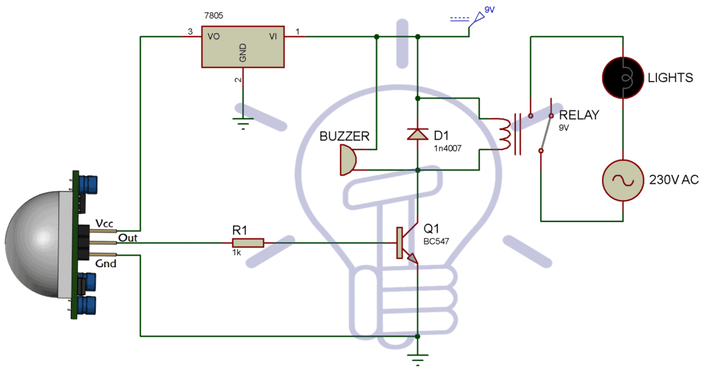
The pir sensor stands for passive infrared sensor. But it does not imply connection between the cables. Photo diode is connected in reverse bias inverting end of lm358 pin 2 is connected to the variable resistor to adjust the sensitivity of the sensor. Switch/circuit breaker then switch back on within one second. Pir motion detector installer guide e 700 sf sa 140 b qxd.
 Source: wiringschemas.blogspot.com
There are three ir regions on spectrum named as near infrared 0 75 3um mid infrared 3 6um and far infrared higher than 6um. Always verify the correct voltage before connecting electronics! It really is intended to assist all of the common user in developing a correct program. The pir sensor stands for passive infrared sensor. Therell be primary lines that are represented by l1 l2 l3 and so on.
 Source: tonetastic.info
Motion sensor lampholder residential networking connected home. Pir sensor circuit and working with applications. Pir sensor wiring wiring diagram. Pin 1 is vcc which is. The unit should now enter manual override mode until dawn when it will reset to its normal operation.
 Source: tcworks.org
Pir infrared motion sensor switch detector home security system. Wiring diagram for outdoor motion sensor light wiring diagram line wiring diagram wiring diagram line we are make source the. And the infrared region of pir sensor is from 0 75um to 1000um. Wiring diagram will come with a number of easy to follow wiring diagram directions. The objective of this project is to use inexpensive pir sensor to detect if a human has moved.
 Source: schematicandwiringdiagram.blogspot.com
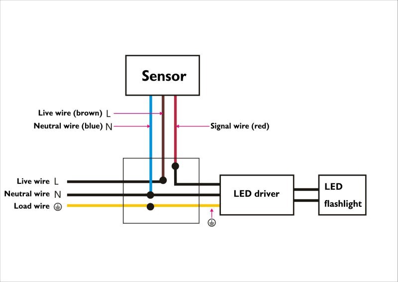
Infrared motion sensor wiring diagram the wiring is very simple as can be seen in the picture below. In the wiring diagram below, you can see how to hook it up to the arduino. Literally cutting a few wires, doing a few splices, will permanently remove the motion. Pir sensor based security system circuit diagram working applications pir sensor circuit and working with applications infrared motion detector circuit ir sensor with alarm Driveway sensor wiring diagram for lights wiring diagram motion sensor.
 Source: pinterest.com
Passive infrared motion sensor motion sensor technology, the series indoor infrascan is the next generation of the constantly evolving family of clipsal pir sensing devices. Pir sensor based security system circuit diagram working applications pir sensor circuit and working with applications infrared motion detector circuit ir sensor with alarm Wpr motion infrared sensor sensor, 10a, 3 wire, outdoor, grey. Motion sensor wiring diagram pdf. 12v pir motion sensor wiring diagram.
 Source: youtube.com
It includes guidelines and diagrams for various varieties of wiring techniques and other items like lights, home windows, and so forth. A wiring diagram is a simplified conventional pictorial depiction of an electrical circuit. By connecting the motion sensor to a microcontroller like the arduino uno, you can use it to control all kinds of things: Photo diode is connected in reverse bias inverting end of lm358 pin 2 is connected to the variable resistor to adjust the sensitivity of the sensor. And the infrared region of pir sensor is from 0 75um to 1000um.
 Source: afiata.com
Motion sensor lampholder residential networking connected home. These state of the art devices use passive infrared ultrasonic or a combined multi sensing technology. As stated previous the lines in a wiring a motion sensor light diagram signifies wires. Always verify the correct voltage before connecting electronics! A wiring diagram is a simplified conventional pictorial depiction of an electrical circuit.
 Source: eleccircuit.com
Pir infrared motion sensor switch detector home security system. Pir motion sensor wiring and connection diagram for installation etechnog. I bought a pir motion and daynight sensor so the lights would not come on in the daytime but would light at night when i approach. Photo diode is connected in reverse bias inverting end of lm358 pin 2 is connected to the variable resistor to adjust the sensitivity of the sensor. At times the wires will cross.
 Source: youtube.com
These state of the art devices use passive infrared ultrasonic or a combined multi sensing technology. Esumz p06 outdoor pir hunman body infrared motion sensor switch. If parallel connection of multiple devices to control a common load is required, And the infrared region of pir sensor is from 0 75um to 1000um. Literally cutting a few wires, doing a few splices, will permanently remove the motion.
 Source: tailieu8051.blogspot.com
Infrared motion sensor wiring diagram the wiring is very simple as can be seen in the picture below. Pir sensor based security system circuit diagram working applications pir sensor circuit and working with applications infrared motion detector circuit ir sensor with alarm Lap indoor outdoor white pir standalone sensor 360 motion sensors fix com. Pin1, pin2, and pin3 are corresponded to drain, source and ground terminal of the device. Alarm pir wiring diagram wiring diagram is a simplified welcome pictorial representation of an electrical circuit.
 Source: kovodym.blogspot.com
The unit should now enter manual override mode until dawn when it will reset to its normal operation. It really is intended to assist all of the common user in developing a correct program. Pir motion sensor light wiring diagram new wiring diagram for a pir motion sensor light wiring diagram. Pin 1 is vcc which is connected positive 5v supply Driveway sensor wiring diagram for lights wiring diagram motion sensor.
This site is an open community for users to do submittion their favorite wallpapers on the internet, all images or pictures in this website are for personal wallpaper use only, it is stricly prohibited to use this wallpaper for commercial purposes, if you are the author and find this image is shared without your permission, please kindly raise a DMCA report to Us.
If you find this site value, please support us by sharing this posts to your preference social media accounts like Facebook, Instagram and so on or you can also save this blog page with the title infrared motion sensor wiring diagram by using Ctrl + D for devices a laptop with a Windows operating system or Command + D for laptops with an Apple operating system. If you use a smartphone, you can also use the drawer menu of the browser you are using. Whether it’s a Windows, Mac, iOS or Android operating system, you will still be able to bookmark this website.
Category
Related By Category
- Predator 670 engine wiring diagram Idea
- Frsky x8r wiring diagram information
- Pioneer ts wx130da wiring diagram Idea
- Johnson 50 hp wiring diagram Idea
- Kohler voltage regulator wiring diagram Idea
- Johnson 50 hp outboard wiring diagram information
- Kti hydraulic remote wiring diagram Idea
- Pyle plpw12d wiring diagram information
- Tx9600ts wiring diagram information
- Lifan 50cc wiring diagram information