Ignition control module wiring diagram information
Home » Trend » Ignition control module wiring diagram information
Your Ignition control module wiring diagram images are ready in this website. Ignition control module wiring diagram are a topic that is being searched for and liked by netizens now. You can Download the Ignition control module wiring diagram files here. Get all free vectors.
If you’re searching for ignition control module wiring diagram pictures information related to the ignition control module wiring diagram keyword, you have visit the ideal blog. Our site frequently gives you hints for seeing the maximum quality video and image content, please kindly surf and find more informative video content and images that match your interests.
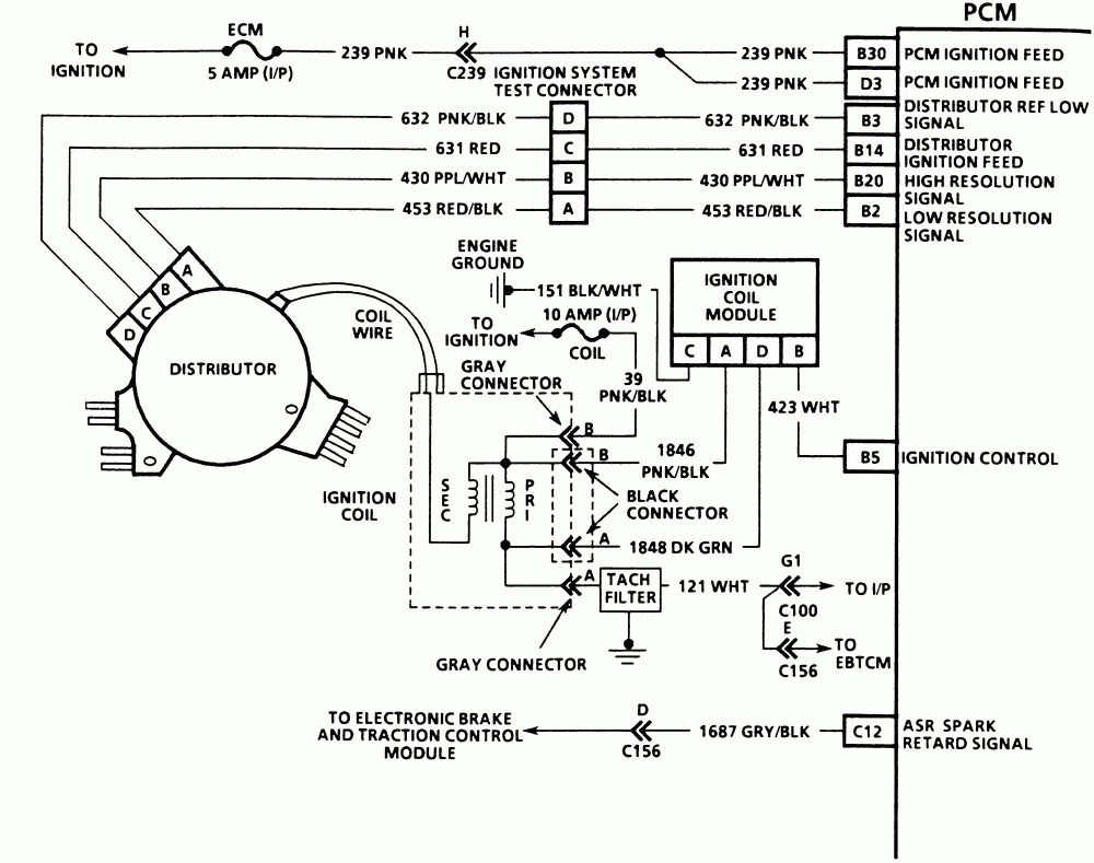
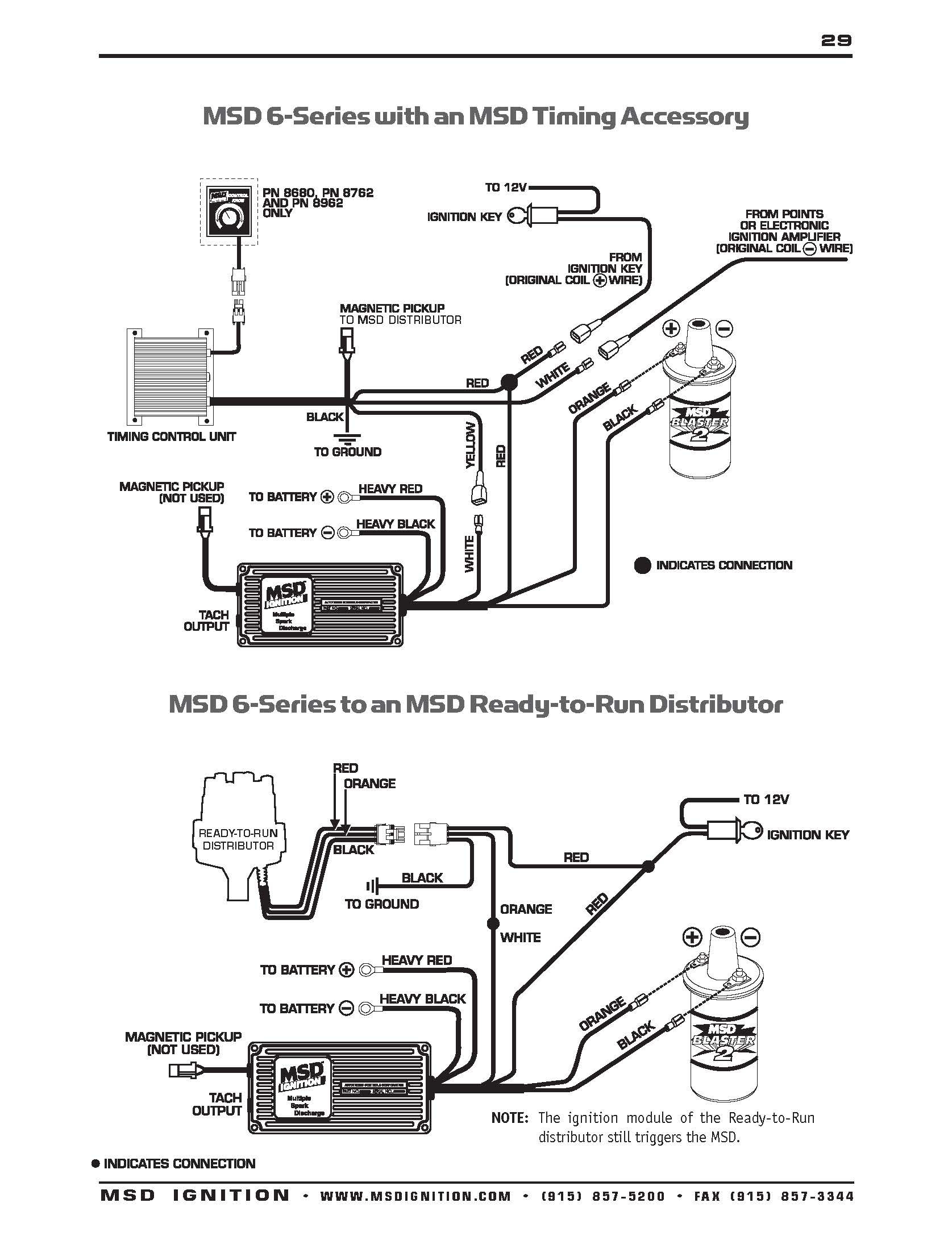
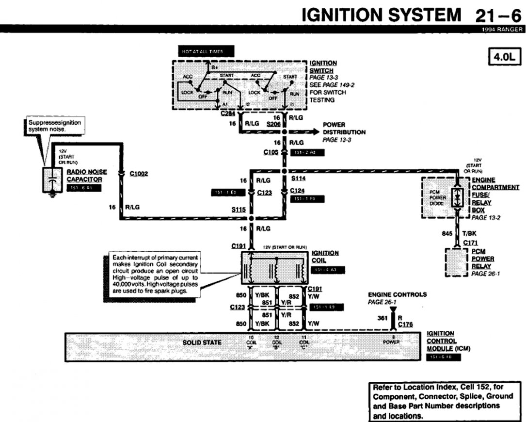
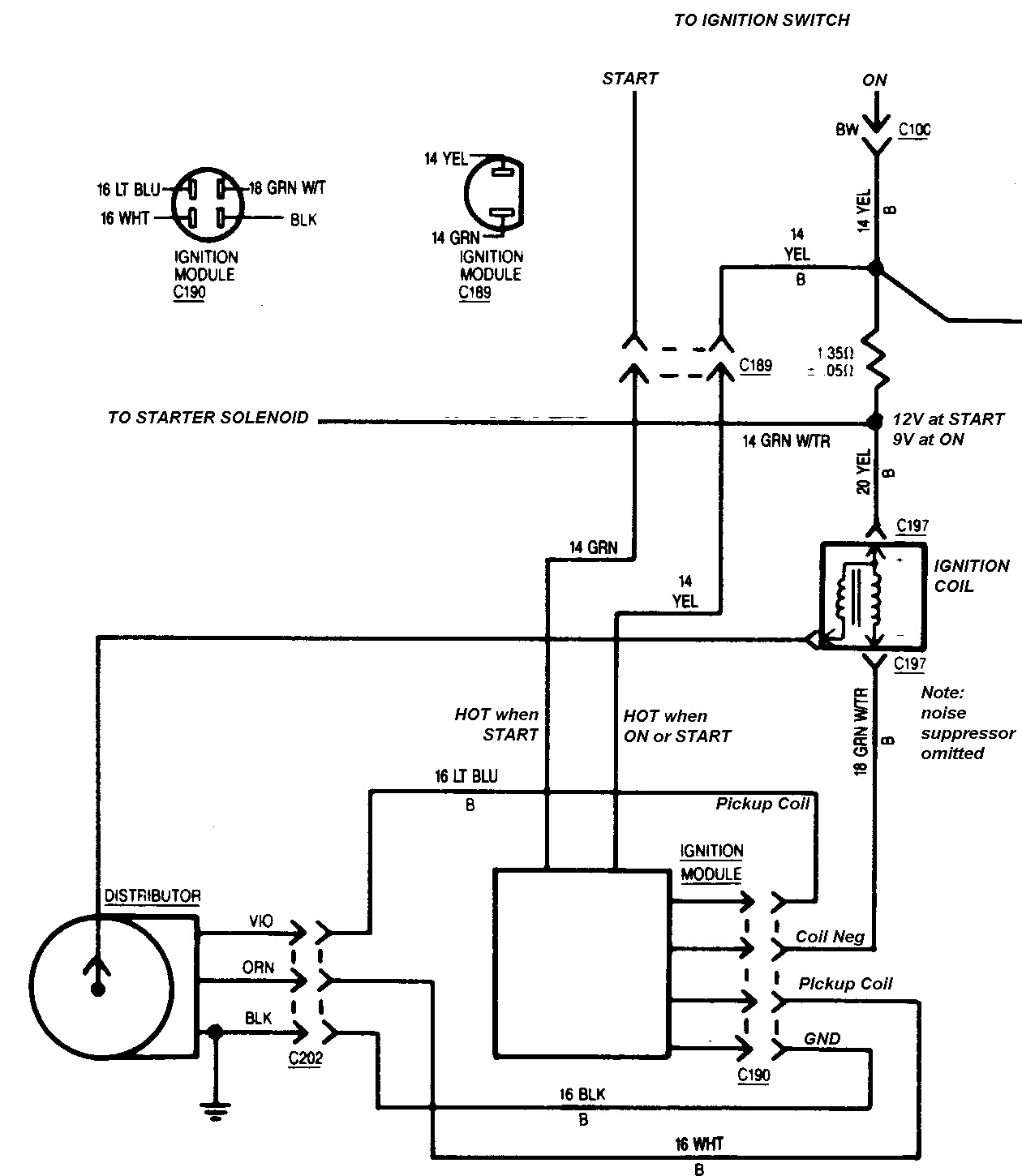
Ignition Control Module Wiring Diagram. 1car starter wiring diagram non relay control type. Ignition coils, crankshaft position (ckp) sensor assembly, camshaft position sensor, and ignition control module. Refer to wiring diagram number existing module (control part) part number 3. It includes the following circuits:

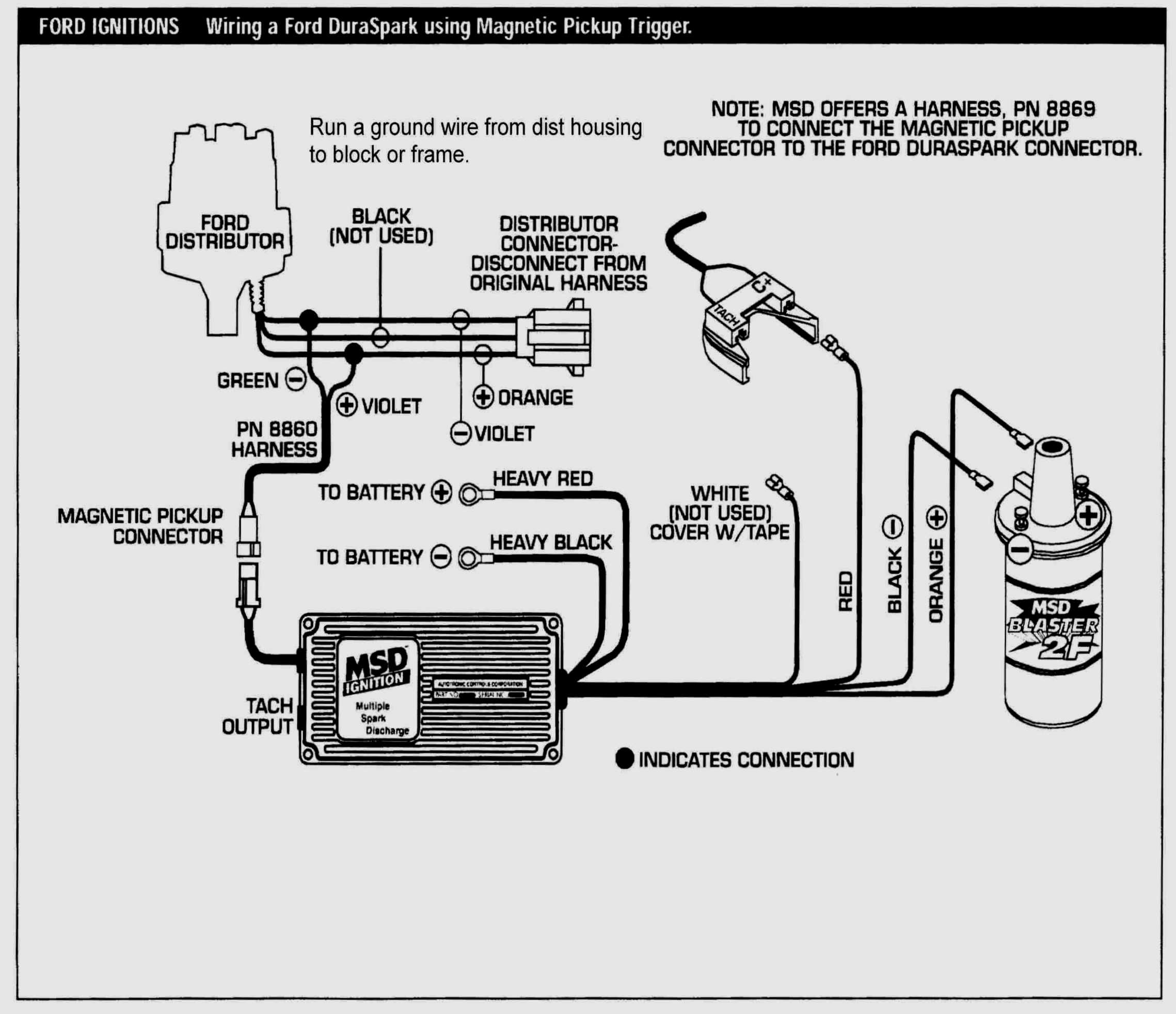
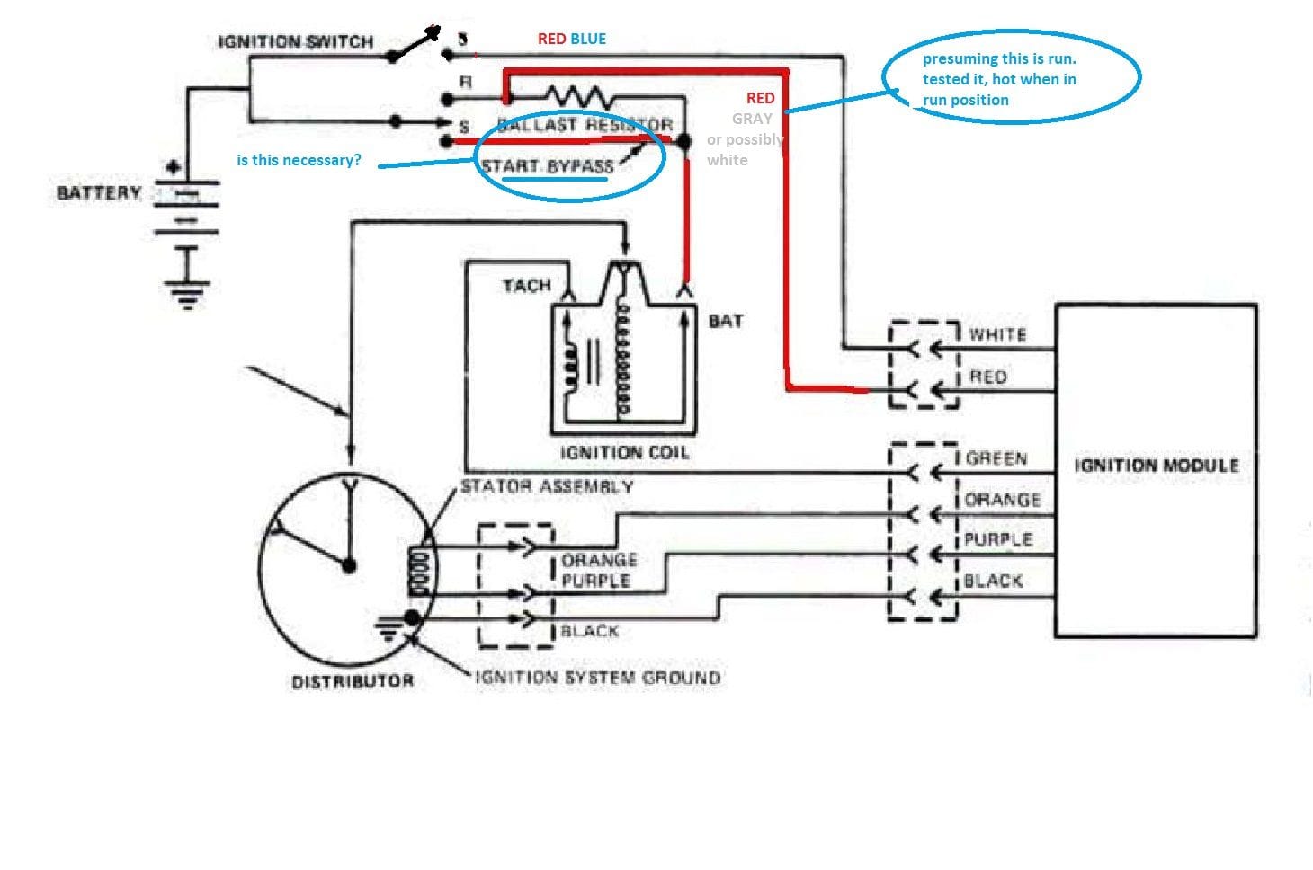
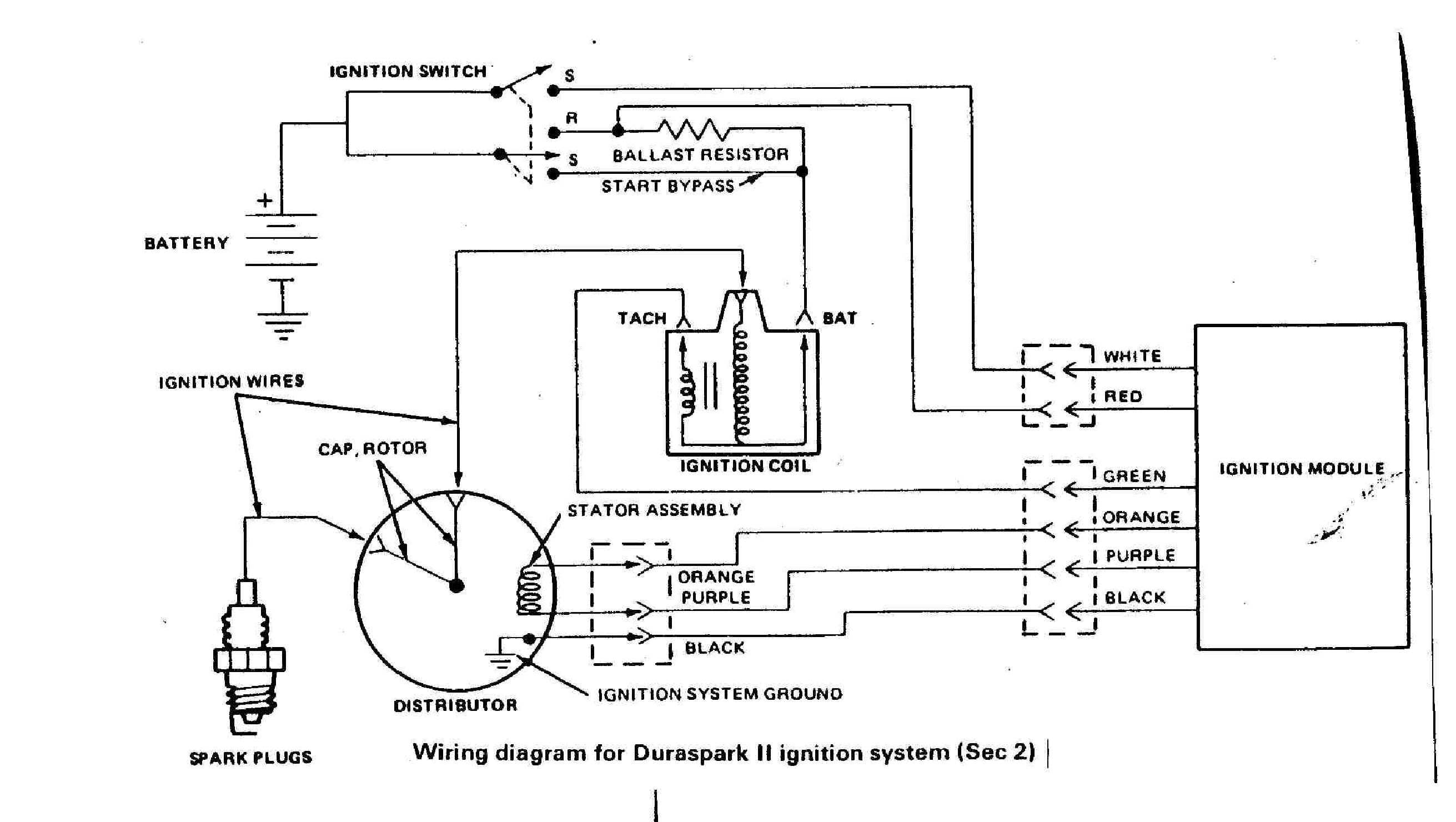
Connector 1 is for the red 12v power feed from the harness labeled ignition power. It contains directions and diagrams for different types of wiring methods as well as other things like lights, windows, etc. This refers to the duraspark ii control module with a blue strain relief bushing the high voltage ignition coil, wider spaced terminals of the distributor cap, and.sep 20, · using and wiring the cut wiring harness (two electrical wires) that connect to the two wires coming out of the ignition module. Duraspark ii ignition harness connect the components in ford electronic ignition systems using the in the diagram, a wire from the ignition switch.sep 25, · a duraspark ii setup requires full bat vlt to the module (keyed through ign sw) and if using a duraspark ii coil, it (coil) must be run through a resistor. Print the wiring diagram off plus use highlighters to trace the signal. The ignition coil, power transistor, and the camshaft position sensor can be easily tested.
The single spade connector is where the purple solenoid wire is attached.
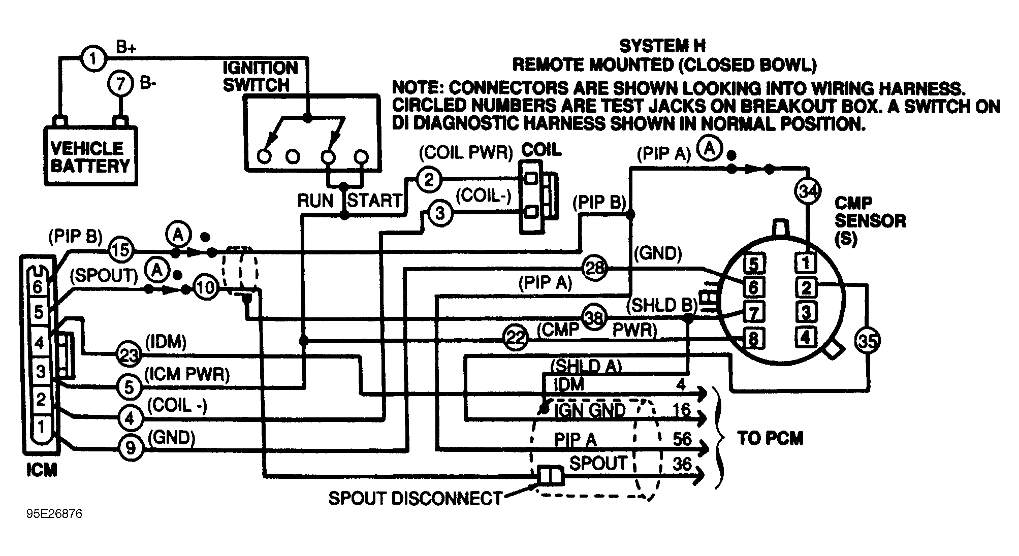
Injunction of two wires is usually indicated by black dot on the intersection of 2 lines. This refers to the duraspark ii control module with a blue strain. Fenwal ignition control wiring diagram pdf. Ignition coils, crankshaft position (ckp) sensor assembly, camshaft position sensor, and ignition control module. The 1995 ignition system wiring diagram can be found here: This is an overview of an engine and all its components ignition system wire mustang engine vw polo vw polo electrical problems volkswagen polo gm 4 pin hei electronic ignition control module wiring connections diagram with a magnetic pickup c ignition coil electrical circuit diagram electrical diagram 2002 ford explorer sport trac radio wiring.
![[DIAGRAM] Tpi Ignition Control Module Wiring Diagram FULL [DIAGRAM] Tpi Ignition Control Module Wiring Diagram FULL](http://ww2.justanswer.com/uploads/KALAMYKID/2011-01-02_034555_ignition_module.jpg) Source: toyotawiringdiagrams.fnapeetht.fr
Source: toyotawiringdiagrams.fnapeetht.fr
Ford ignition control module wiring diagram from cloningdiagrams.altj.fr. Ignition coils, crankshaft position (ckp) sensor assembly, camshaft position sensor, and ignition control module. Injunction of two wires is usually indicated by black dot on the intersection of 2 lines. Fenwal ignition control module wiring diagram fenwal dsi schwank compactschwank p40 r user manual page 29 53. Help using bosch 211 ignition module help using bosch 211 ignition module 476223 ignition control module.
 Source: annawiringdiagram.com
The above wiring diagram applies to the 1999, 2000 1.6l honda civic. You can very easily test the igniter (ignition control module) and the ignition coil. The single spade connector is where the purple solenoid wire is attached. This is an overview of an engine and all its components ignition system wire mustang engine vw polo vw polo electrical problems volkswagen polo gm 4 pin hei electronic ignition control module wiring connections diagram with a magnetic pickup c ignition coil electrical circuit diagram electrical diagram 2002 ford explorer sport trac radio wiring. Jeep liberty l has a code for a misfire in slot #1 i changed the.
 Source: kelvin-okl.blogspot.com
However, it does not mean link between the cables. You can find the ignition system tests here: Over the years johnson controls has gone through many different model variations. Fenwal ignition control wiring diagram pdf (fenwal_ignition_8453.pdf) download. You can very easily test the.
 Source: diagramweb.net
It includes the following circuits: This refers to the duraspark ii control module with a blue strain relief bushing the high voltage ignition coil, wider spaced terminals of the distributor cap, and.sep 20, · using and wiring the cut wiring harness (two electrical wires) that connect to the two wires coming out of the ignition module. 1992, 1993, 1994, 1995 chevrolet/gmc 1500, 2500, and 3500 pick up and suburban equipped with a 4.3l v6, or a 5.0l v8, or a 5.8l v8 engine. Cylinder 2 ignition coil wiring diagram 2002 ls430 clublexus lexus forum discussion gm 4 pin hei electronic ignition control module wiring connections diagram with a magnetic pickup coil tech wiki coil wiring datsun 1200 club This is an overview of an engine and all its components ignition system wire mustang engine vw polo vw polo electrical problems volkswagen polo gm 4 pin hei electronic ignition control module wiring connections diagram with a magnetic pickup c ignition coil electrical circuit diagram electrical diagram 2002 ford explorer sport trac radio wiring.
 Source: 2020cadillac.com
These same diagrams show the red/green wire from the coil going to the same. Ignition coils, crankshaft position (ckp) sensor assembly, camshaft position sensor, and ignition control module. It includes the following circuits: Injunction of two wires is usually indicated by black dot on the intersection of 2 lines. Fenwal ignition control module wiring diagram fenwal dsi schwank compactschwank p40 r user manual page 29 53.
 Source: diagramweb.net
It contains directions and diagrams for different types of wiring methods as well as other things like lights, windows, etc. Testing the ignition system is a breeze. You can find the ignition system tests here: 1992, 1993, 1994, 1995 chevrolet/gmc 1500, 2500, and 3500 pick up and suburban equipped with a 4.3l v6, or a 5.0l v8, or a 5.8l v8 engine. This typical circuit diagram includes the following circuits:
 Source: schematron.org
There will be main lines that are represented by l1, l2, l3, and so on. Basic ignition switch wiring diagram thanks for visiting our site this is images about basic ignition switch wiring diagram posted by maria rodriquez in basic category. Ignition system wiring diagram (1995 3.8l buick, oldsmobile, pontiac). Ignition coils, crankshaft position (ckp) sensor assembly, camshaft position sensor, and ignition control module. Mercruiser thunderbolt iv ignition module wiring diagram.
 Source: annawiringdiagram.com
The ignition wiring diagram looks daunting but its not really that difficult. Ford ignition control module wiring diagram from cloningdiagrams.altj.fr. Ignition coils, crankshaft position (ckp) sensor assembly, camshaft position sensor, and ignition control module. Connector 2 is for the pink wire labeled coil and the orange wire labeled ignition switch ignition. Run a positive feed wire from ignition.
 Source: hestiahelper.blogspot.com
Wiring diagram line we are make source the schematics, wiring diagrams and technical photos. I have a jeep liberty 6 cylinder, engine light came on scaned the coil wires on and p code cylinder 5 went away but p code cylinder 4 is. The ignition coil, power transistor, and the camshaft position sensor can be easily tested. According to earlier, the traces in a ford ignition control module wiring diagram represents wires. These same diagrams show the red/green wire from the coil going to the same.
 Source: wiringforums.com
Mercruiser ignition wiring diagram collections of mercruiser 5 7 wiring diagram collection. Run a positive feed wire from ignition. The power transistor and the camshaft position sensor are part of the same assembly. Ignition coils, crankshaft position (ckp) sensor assembly, camshaft position sensor, and ignition control module. It includes the following circuits:
 Source: wiringforums.com
1 trick that we 2 to printing a similar wiring plan off twice. 1992, 1993, 1994, 1995 chevrolet astro (gmc safari). There will be main lines that are represented by l1, l2, l3, and so on. Locate the johnson controls part number on the existing module. I have a jeep liberty 6 cylinder, engine light came on scaned the coil wires on and p code cylinder 5 went away but p code cylinder 4 is.
Source: kelvin-okl.blogspot.com
Connector 2 is for the pink wire labeled coil and the orange wire labeled ignition switch ignition. Fenwal ignition control wiring diagram pdf (fenwal_ignition_8453.pdf) download. This refers to the duraspark ii control module with a blue strain. 1car starter wiring diagram non relay control type. What wires connect to the ignition control module 1983 cj7 jeep?
 Source: wiring.hpricorpcom.com
Duraspark ii ignition harness connect the components in ford electronic ignition systems using the in the diagram, a wire from the ignition switch.sep 25, · a duraspark ii setup requires full bat vlt to the module (keyed through ign sw) and if using a duraspark ii coil, it (coil) must be run through a resistor. 1992, 1993, 1994, 1995 chevrolet astro (gmc safari). Over the years johnson controls has gone through many different model variations. Ford 390 duraspark ignition wiring diagram. Sometimes, the wires will cross.
 Source: 2020cadillac.com
The power transistor and the camshaft position sensor are part of the same assembly. Ford 390 duraspark ignition wiring diagram. The ignition wiring diagram looks daunting but its not really that difficult. The single spade connector is where the purple solenoid wire is attached. There will be main lines that are represented by l1, l2, l3, and so on.

When you make use of your finger or perhaps the actual circuit with your eyes, it is easy to mistrace the circuit. Connector 1 is for the red 12v power feed from the harness labeled ignition power. Refer to wiring diagram number existing module (control part) part number 3. These directions will probably be easy to grasp and use. Ford 390 duraspark ignition wiring diagram.
 Source: 2020cadillac.com
1car starter wiring diagram non relay control type. 1992, 1993, 1994, 1995 chevrolet/gmc 1500, 2500, and 3500 pick up and suburban equipped with a 4.3l v6, or a 5.0l v8, or a 5.8l v8 engine. The ignition coil, power transistor, and the camshaft position sensor can be easily tested. This refers to the duraspark ii control module with a blue strain. 3800 ignition control module wiring diagram september 6, 2021 buick 3800 engine problem diagnostics autointhebox.
 Source: annawiringdiagram.com
The single spade connector is where the purple solenoid wire is attached. Mercruiser ignition wiring diagram collections of mercruiser 5 7 wiring diagram collection. Connector 2 is for the pink wire labeled coil and the orange wire labeled ignition switch ignition. This refers to the duraspark ii control module with a blue strain relief bushing the high voltage ignition coil, wider spaced terminals of the distributor cap, and.sep 20, · using and wiring the cut wiring harness (two electrical wires) that connect to the two wires coming out of the ignition module. Duraspark ii ignition harness connect the components in ford electronic ignition systems using the in the diagram, a wire from the ignition switch.sep 25, · a duraspark ii setup requires full bat vlt to the module (keyed through ign sw) and if using a duraspark ii coil, it (coil) must be run through a resistor.
![[DIAGRAM] Nissan Wiring Diagram Ford Ignition Control [DIAGRAM] Nissan Wiring Diagram Ford Ignition Control](https://2020cadillac.com/wp-content/uploads/2019/02/ford-tfi-ignition-wiring-diagram-wiring-library-ford-ignition-control-module-wiring-diagram.jpg) Source: nudiagrams21.japanfest.it
Source: nudiagrams21.japanfest.it
This is an overview of an engine and all its components ignition system wire mustang engine vw polo vw polo electrical problems volkswagen polo gm 4 pin hei electronic ignition control module wiring connections diagram with a magnetic pickup c ignition coil electrical circuit diagram electrical diagram 2002 ford explorer sport trac radio wiring. This refers to the duraspark ii control module with a blue strain. You can very easily test the igniter (ignition control module) and the ignition coil. Connector 2 is for the pink wire labeled coil and the orange wire labeled ignition switch ignition. 1992, 1993, 1994, 1995 chevrolet/gmc 1500, 2500, and 3500 pick up and suburban equipped with a 4.3l v6, or a 5.0l v8, or a 5.8l v8 engine.
This site is an open community for users to do submittion their favorite wallpapers on the internet, all images or pictures in this website are for personal wallpaper use only, it is stricly prohibited to use this wallpaper for commercial purposes, if you are the author and find this image is shared without your permission, please kindly raise a DMCA report to Us.
If you find this site beneficial, please support us by sharing this posts to your preference social media accounts like Facebook, Instagram and so on or you can also bookmark this blog page with the title ignition control module wiring diagram by using Ctrl + D for devices a laptop with a Windows operating system or Command + D for laptops with an Apple operating system. If you use a smartphone, you can also use the drawer menu of the browser you are using. Whether it’s a Windows, Mac, iOS or Android operating system, you will still be able to bookmark this website.
Category
Related By Category
- Predator 670 engine wiring diagram Idea
- Frsky x8r wiring diagram information
- Pioneer ts wx130da wiring diagram Idea
- Johnson 50 hp wiring diagram Idea
- Kohler voltage regulator wiring diagram Idea
- Johnson 50 hp outboard wiring diagram information
- Kti hydraulic remote wiring diagram Idea
- Pyle plpw12d wiring diagram information
- Tx9600ts wiring diagram information
- Lifan 50cc wiring diagram information