Ignition coil wiring diagram with resistor Idea
Home » Trend » Ignition coil wiring diagram with resistor Idea
Your Ignition coil wiring diagram with resistor images are available. Ignition coil wiring diagram with resistor are a topic that is being searched for and liked by netizens now. You can Find and Download the Ignition coil wiring diagram with resistor files here. Get all free photos and vectors.
If you’re searching for ignition coil wiring diagram with resistor pictures information linked to the ignition coil wiring diagram with resistor topic, you have pay a visit to the right blog. Our website always provides you with suggestions for seeing the highest quality video and image content, please kindly hunt and locate more informative video articles and graphics that fit your interests.
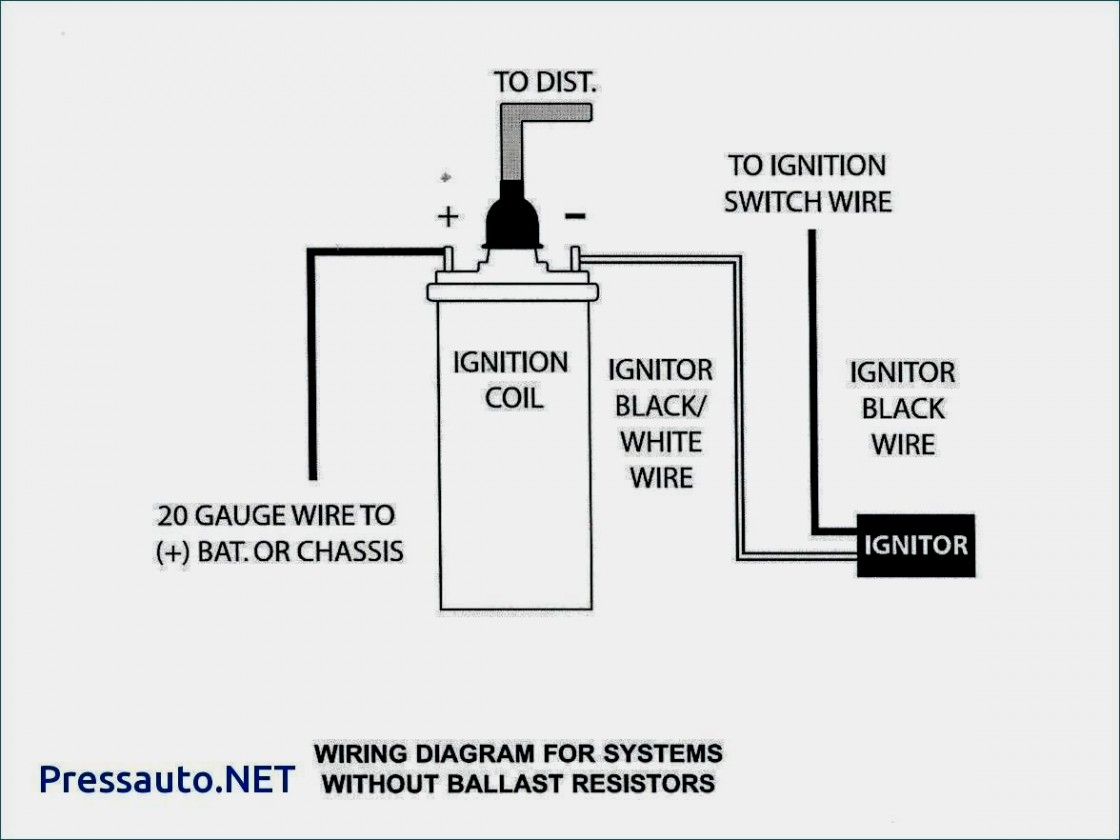
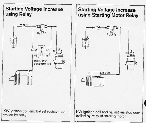
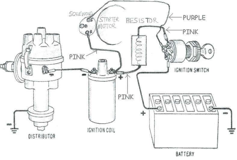
Ignition Coil Wiring Diagram With Resistor. By bettina brunston 8 nov, 2017 leave a comment. Diagram attached for wiring of points dizzy and coil with ballast resistor. You just need to have a good comprehension on various kinds of wiring and also their functions. From the other terminal on the resistor a wire goes to the positive on the coil.
 Ignition Coil Ballast Resistor Wiring Diagram Fuse Box From stickerdeals.net
Route the other end of the wire to one terminal of the ballast resistor. Ad additional energy produces quicke starts and smoother idle. When you use your finger or stick to the circuit together with your eyes its easy to mistrace the circuit. Basic ignition system wiring diagram. Additionally, there are other components like floor, switch, engine, and inductor. From the other terminal on the resistor a wire goes to the positive on the coil.
One second and ill pull up the wiring diagram.
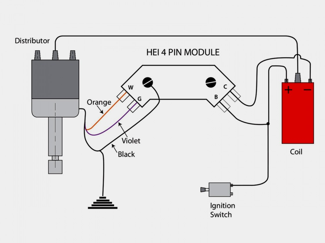
The ignition system consists of an ignition coil, distributor, distributor cap, rotor, plug wires and spark plugs. Ignition coil to ignition resistor wire. This diagram shows the parts of your ignition system. Connect one side of the ballast resistor to the positive side of the coil. When you use your finger or stick to the circuit together with your eyes its easy to mistrace the circuit. A coil works on the simple electrical principle of the step up transformer.
 Source: amee055.blogspot.com
Connect one side of the ballast resistor to the positive side of the coil. Connect it to the ignition terminal of the ignition switch. As jdub said, you can use this resistive wire to control a relay that, in turn, provides battery voltage (nominally, 12v) to the pertronix ignitor and to a pertronix coil. Ballast resistor wiring diagram points. Diagram wiring diagram ballast resistor ignition coil full version hd quality ignition coil wiringout aube siae fr.
 Source: stickerdeals.net
When you use your finger or stick to the circuit together with your eyes its easy to mistrace the circuit. The dme reads the voltage dropped on this resistor in synch with the ignition timing to detect which coil is bad if any. It shows the components of the circuit as streamlined forms as well as the power and also signal links between the tools. Cut the wire, strip 1/2 inch of insulation and crimp on a terminal. Connect one side of the ballast resistor to the positive side of the coil.
 Source: 2020cadillac.com
Accel points eliminator wiring diagram using oem primary resistance wire figure 4 distributor. In a points type ignition the ballast resistor would help to keep the spark down and the coil from being burned up too quickly. If not, the arrangement won’t function as. The purpose of the ignition system is to create a spark that will ignite the fuel air mixture in the cylinder of an engine. Ballast resistor compatible ignition coils ballast ignition troubleshooting accuspark wiring diagrams.
 Source: sl113.org
Ignition coil ballast resistor wiring diagram. Wiring diagram and schematic role wiring diagram ignition coil resistor october 30, 2020 1 margaret byrd From the other terminal on the resistor a wire goes to the positive on the coil. Here is a picture gallery about ignition coil ballast resistor wiring diagram complete with the description of the image, please find the image you need. See more articles in category:

Basic ignition system wiring diagram. From the provided schematic, thank you bob, that 240 ohms resistor is for measure the current flow through the secondary coils. You just need to have a good comprehension on various kinds of wiring and also their functions. The start coil wire should still have 12 volts. 800 x 600 px, source:
 Source: tops-stars.com
The purpose of the ignition system is to create a spark that will ignite the fuel air mixture in the cylinder of an engine. This diagram shows the parts of your ignition system. The most common elements are capacitor, resistorbattery. It shows the components of the circuit as streamlined forms as well as the power and also signal links between the tools. Failure to use an ignition ballast resistor will pn 8214 in the.
 Source: schematicandwiringdiagram.blogspot.com
240z coil and ballast resistor installation help zdriver com replacing electronic ignition completely in 1970s 1980s ignition coil ballast resistor wiring diagram wiring Click to see full answer. The ignition coil is essentially a low voltage to high voltage transformer with about 100 to 1 ratio of windings and voltage. Basic ignition system wiring diagram. Wiring diagram for ignition coil more information find this pin and more on 63 f100 wiring by ben platt.

Its value doesn�t have to be precise as long as it is not damaged as open or shorted. See more articles in category: This applies to all old cub cadet ford jacobsen john deere wheel horse case and. Ignition coils of this type. Ballast resistor wiring diagram points.
 Source: cars-trucks24.blogspot.com
Every symbol that’s shown on the diagram reveals specific circuit element. From the other terminal on the resistor a wire goes to the positive on the coil. Connect it to the ignition terminal of the ignition switch. When you hit the starter buttonkey the coil is still seeing. Thereforemagneto ignition is very popularly used in racing cars.
 Source: alamtiga08santomikhael.blogspot.com
Every symbol that’s shown on the diagram reveals specific circuit element. When you use your finger or stick to the circuit together with your eyes its easy to mistrace the circuit. It shows the components of the circuit as simplified shapes and the facility and signal contacts in the midst of the devices. The ignition coil is essentially a low voltage to high voltage transformer with about 100 to 1 ratio of windings and voltage. A resistor that has the property of increasing in resistance as current flowing through it increases and decreasing in resistance as current decreases.

Ballast resistor compatible ignition coils ballast ignition troubleshooting accuspark wiring diagrams. Every symbol that’s shown on the diagram reveals specific circuit element. Dec 10 2016 automotive wiring diagram resistor to coil connect to distributor wiring diagram for ignition coil. The most common elements are capacitor, resistorbattery. 12 volt ignition coil wiring diagram vincent motorcycle electrics.
 Source: alannahbig.blogspot.com
Connect to the ballast resistor. From the provided schematic, thank you bob, that 240 ohms resistor is for measure the current flow through the secondary coils. 700 in the wire between the ignition switch and the coil. Ignition coil ballast resistor wiring diagram with ignition coil ballast resistor wiring diagram, image size 609 x 360 px, and to view image details please click the image. The dme reads the voltage dropped on this resistor in synch with the ignition timing to detect which coil is bad if any.
 Source: stickerdeals.net
Click to see full answer. From my recollection it delivers a nastier spark than the legendary ford model t ignition coil. Failure to use an ignition ballast resistor will pn 8214 in the. Discussion in 1960 1966 started by ol betsy dec 20 2006. You are able to usually depend on wiring diagram as an important reference that will enable you to save time and money.
 Source: dentistmitcham.com
A coil works on the simple electrical principle of the step up transformer. One second and ill pull up the wiring diagram. Dec 10 2016 automotive wiring diagram resistor to coil connect to distributor wiring diagram for ignition coil. Ballast resistor wiring diagram points. 12 volt ignition coil wiring diagram vincent motorcycle electrics.
 Source: wiringforums.com
The resistive wire runs from the ignition switch to the stock coil. Failure to use an ignition ballast resistor will pn 8214 in the. The resistive wire runs from the ignition switch to the stock coil. Click to see full answer. From my recollection it delivers a nastier spark than the legendary ford model t ignition coil.
 Source: facybulka.me
Cut the wire, strip 1/2 inch of insulation and crimp on a terminal. Dec 10 2016 automotive wiring diagram resistor to coil connect to distributor wiring diagram for ignition coil. You are able to usually depend on wiring diagram as an important reference that will enable you to save time and money. No brainer wiring question ballast. Make sure to attach securely to the connecting terminal, by wrapping the wire around the post and tightening with a screwdriver.
 Source: 2020cadillac.com
By bettina brunston 8 nov, 2017 leave a comment. Diagram wiring diagram ballast resistor ignition coil full version hd quality ignition coil wiringout aube siae fr. According to earlier, the traces in a ignition coil wiring diagram represents wires. Failure to use an ignition ballast resistor will pn 8214 in the. Dec 10 2016 automotive wiring diagram resistor to coil connect to distributor wiring diagram for ignition coil.
 Source: stickerdeals.net
Wiring diagram for ignition coil more information find this pin and more on 63 f100 wiring by ben platt. We have 8 diagram about harley ignition wiring diagram for wiring ignition coil including images pictures photos and more. From the other terminal on the resistor a wire goes to the positive on the coil. Definitely run a ballast resistor. Ignition coil ballast resistor wiring diagram.
This site is an open community for users to do sharing their favorite wallpapers on the internet, all images or pictures in this website are for personal wallpaper use only, it is stricly prohibited to use this wallpaper for commercial purposes, if you are the author and find this image is shared without your permission, please kindly raise a DMCA report to Us.
If you find this site convienient, please support us by sharing this posts to your preference social media accounts like Facebook, Instagram and so on or you can also bookmark this blog page with the title ignition coil wiring diagram with resistor by using Ctrl + D for devices a laptop with a Windows operating system or Command + D for laptops with an Apple operating system. If you use a smartphone, you can also use the drawer menu of the browser you are using. Whether it’s a Windows, Mac, iOS or Android operating system, you will still be able to bookmark this website.
Category
Related By Category
- Predator 670 engine wiring diagram Idea
- Frsky x8r wiring diagram information
- Pioneer ts wx130da wiring diagram Idea
- Johnson 50 hp wiring diagram Idea
- Kohler voltage regulator wiring diagram Idea
- Johnson 50 hp outboard wiring diagram information
- Kti hydraulic remote wiring diagram Idea
- Pyle plpw12d wiring diagram information
- Tx9600ts wiring diagram information
- Lifan 50cc wiring diagram information