Hydraulic solenoid wiring diagram Idea
Home » Trending » Hydraulic solenoid wiring diagram Idea
Your Hydraulic solenoid wiring diagram images are available. Hydraulic solenoid wiring diagram are a topic that is being searched for and liked by netizens today. You can Get the Hydraulic solenoid wiring diagram files here. Download all royalty-free images.
If you’re searching for hydraulic solenoid wiring diagram images information connected with to the hydraulic solenoid wiring diagram keyword, you have visit the right blog. Our website always provides you with hints for seeing the highest quality video and image content, please kindly hunt and locate more informative video articles and images that fit your interests.
Hydraulic Solenoid Wiring Diagram. And i went through almost a. So in the end it came to this. The hydraulic spool valves target is to reach different mechanical movement of actuator, like to release pressure, stop or redirect the. Wiring diagram arrives with several easy to follow wiring diagram instructions.
 dualdoubleactinghydrauliccylinderpowerunitswiring From target-hydraulics.com
It’s intended to assist all of the common person in building a suitable program. Black wire from hard wired controller b. 91 500sl soft top hydraulic solenoid wiring diagram. If you like this article you can bookmark or share it to your social media account, i thank you. Ac solenoid ac solenoid dc solenoid units: When the piston is fully retracted and hydraulic pressure builds, the unloader (relief) valve will lift and maintain the system’s pressure at setpoint.
Ac solenoid ac solenoid dc solenoid units:
Isarmatic® mark iiia hydraulic systems. Mechanic�s guide right and ensure that your western plow warranty is maintained. How do i wire from 12 volt solenoid hydraulic pump to up down need wiring diagram. Kti hydraulic, inc | hydraulic power unit support inside 12 volt hydraulic pump wiring diagram by admin. Hydraulic solenoid valve wiring diagram from i.ytimg.com. And i went through almost a.
 Source: ricardolevinsmorales.com
And through the electrical schematic. 12 volt solenoid wiring diagram 5 connection wiring diagram center. 91 500sl soft top hydraulic solenoid wiring diagram. Strip 20mm off each of the individual wires. Hydraulic solenoid valve wiring diagram.
 Source: diagramweb.net
For each position that requires power there will be an input from the 12 volt power source and an. These directions will probably be easy to comprehend and use. 12v hydraulic power pack wiring diagram hydraulic solenoid valve wiring diagram best amazing diagram hydraulic system electrical circuit. Wiring a 3 wire solenoid valve to the w100 controller. Pmax = 180bar as long as p<pmax, oil flows.
 Source: worldvisionsummerfest.com
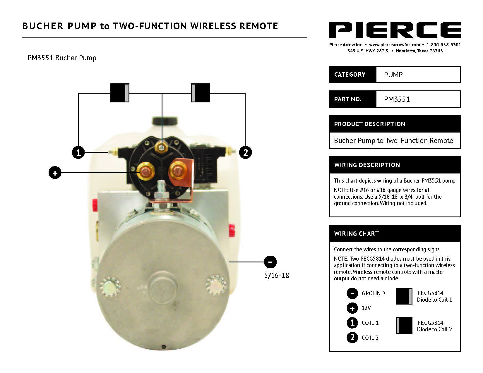
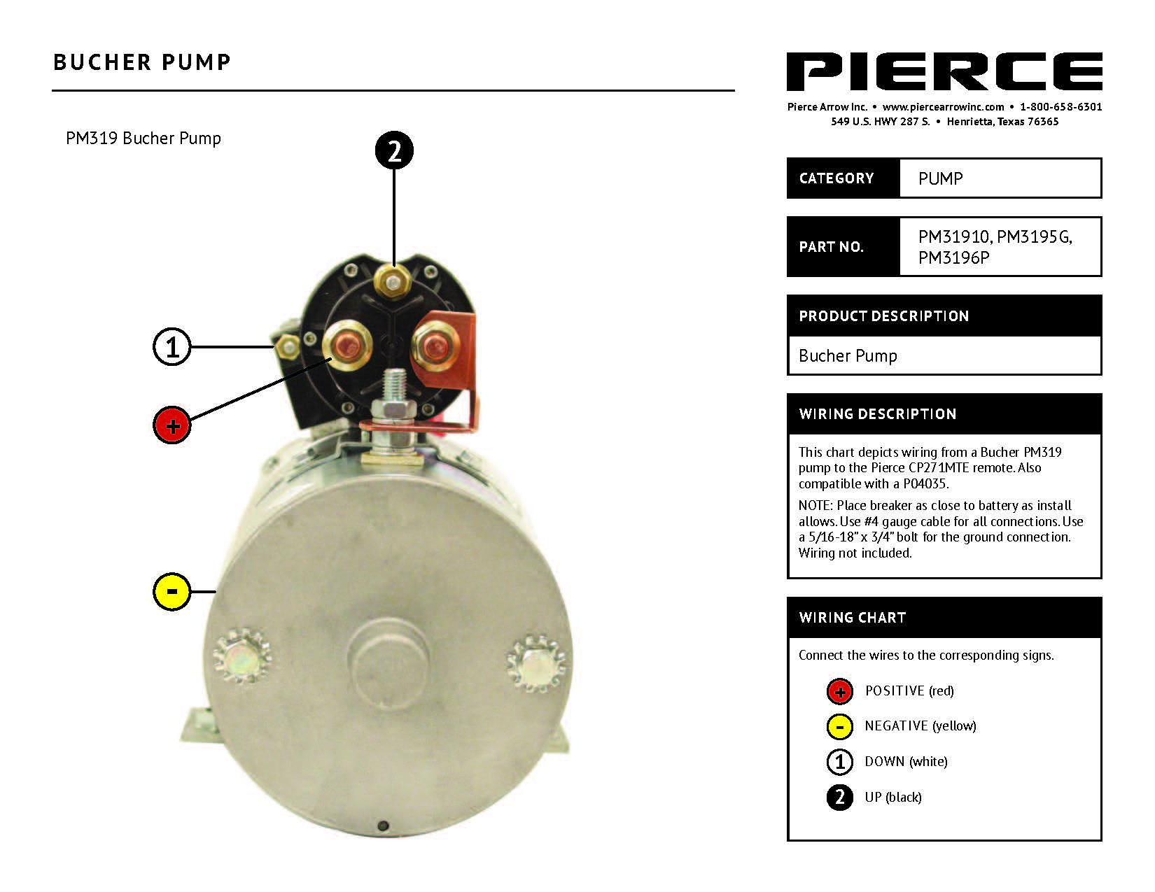
Solenoid switch style wiring grounded style see control box wiring on reverse side attach the (brown) wire to the small post on the solenoid switch this motor is rotated so motor post and solenoid do not show here attach control cord (yellow) wire here attach control cord (green) wire here attach control cord (red) wire here attach control cord (blue) wire here It’s intended to assist all of the common person in building a suitable program. How to wire a din connector If you like this article you can bookmark or share it to your social media account, i thank you. D03, d05 and d08 solenoid valves.pdf.
 Source: annawiringdiagram.com
Print the cabling diagram off plus use highlighters to be able to trace the circuit. These diagrams show the internal components of the solenoids. 91 500sl soft top hydraulic solenoid wiring diagram. Oil cannot flow from 2 to 1. So in the end it came to this.
 Source: worldvisionsummerfest.com
And more, a wireless remote connect wire drawing also show below for single acting hydraulic power pack.this wireless remote can be with a quick connector ,can be changed with our standard 2. And more, a wireless remote connect wire drawing also show below for single acting hydraulic power pack.this wireless remote can be with a quick connector ,can be changed with our standard 2. Discussion starter · #1 · nov 30, 2008. It’s intended to assist all of the common person in building a suitable program. The full manual book is here.
 Source: tops-stars.com
Electrical box wiring double solenoid single solenoid. Pmax = 180bar as long as p<pmax, oil flows. When the piston is fully retracted and hydraulic pressure builds, the unloader (relief) valve will lift and maintain the system’s pressure at setpoint. A wiring diagram is a simplified standard pictorial representation of an electric circuit. Diagram of the “down” circuit.
 Source: annawiringdiagram.com
When you make use of your finger or stick to the circuit together with your eyes, it is easy to mistrace the circuit. These are the solenoid coil terminals. Diagram of the “down” circuit. D03, d05 and d08 solenoid valves.pdf. Solenoid switch style wiring grounded style see control box wiring on reverse side attach the (brown) wire to the small post on the solenoid switch this motor is rotated so motor post and solenoid do not show here attach control cord (yellow) wire here attach control cord (green) wire here attach control cord (red) wire here attach control cord (blue) wire here
Source: wiring121.blogspot.com
How to wire a din connector It reveals the components of the circuit as streamlined shapes, as well as the power and also signal links in between the gadgets. Continuous duty solenoid 12v wiring diagram 4300 wiring diagram intermittent continuous duty 12 24v dc solenoid specification solenoid available voltages 12v dc continuous duty 24v dc. The full manual book is here. 91 500sl soft top hydraulic solenoid wiring diagram.
 Source: worldvisionsummerfest.com
And through the electrical schematic. The diagram below shows a standard hydraulic wiring schematic. And through the electrical schematic. Solenoid switch style wiring grounded style see control box wiring on reverse side attach the (brown) wire to the small post on the solenoid switch this motor is rotated so motor post and solenoid do not show here attach control cord (yellow) wire here attach control cord (green) wire here attach control cord (red) wire here attach control cord (blue) wire here A circuit is generally composed by several components.
 Source: annawiringdiagram.com
Electrical box wiring double solenoid single solenoid. Wiring diagram arrives with several easy to follow wiring diagram instructions. How do i wire from 12 volt solenoid hydraulic pump to up down need wiring diagram. Wiring a 3 wire solenoid valve to the w100 controller. How to wiring dc solenoid valve with 3 wire general electronics arduino forum a hc connecting valves and ac power hydrawise hydraulic selector dv50 instruction diagram summit hydraulics solenoids u70 g70 series mc sealcon camozzi of electrical controlled the responsible scientific control 12v ball uno 2 channel relay project guidance plc controls connections way.
 Source: worldvisionsummerfest.com
If you like this article you can bookmark or share it to your social media account, i thank you. New 12 volt hydraulic pump wiring diagram beautiful a type od part v. Put up by simply admin at january, 1 2014. The hydraulic spool valves target is to reach different mechanical movement of actuator, like to release pressure, stop or redirect the. Black wire from hard wired controller b.
 Source: strategiccontentmarketing.co
Collection of hydraulic solenoid valve wiring diagram. Here are some details of hydraulic pump electric diagram,12vdc hydraulic power unit and 24vdc hydraulic power pack hydraulic circuit diagram and electrical diagram. And more, a wireless remote connect wire drawing also show below for single acting hydraulic power pack.this wireless remote can be with a quick connector ,can be changed with our standard 2. How to wiring dc solenoid valve with 3 wire general electronics arduino forum a hc connecting valves and ac power hydrawise hydraulic selector dv50 instruction diagram summit hydraulics solenoids u70 g70 series mc sealcon camozzi of electrical controlled the responsible scientific control 12v ball uno 2 channel relay project guidance plc controls connections way. A single trick that i actually use is to print the same wiring diagram off twice.
 Source: worldvisionsummerfest.com
The first element is symbol that indicate electrical component from the circuit. The diagram below shows a standard hydraulic wiring schematic. Here are some details of hydraulic pump electric diagram,12vdc hydraulic power unit and 24vdc hydraulic power pack hydraulic circuit diagram and electrical diagram. Solenoid switch style wiring grounded style see control box wiring on reverse side attach the (brown) wire to the small post on the solenoid switch this motor is rotated so motor post and solenoid do not show here attach control cord (yellow) wire here attach control cord (green) wire here attach control cord (red) wire here attach control cord (blue) wire here 12v hydraulic power pack wiring diagram hydraulic solenoid valve wiring diagram best amazing diagram hydraulic system electrical circuit.
 Source: tankbig.com
For each position that requires power there will be an input from the 12 volt power source and an. 12 volt solenoid wiring diagram 5 connection wiring diagram center. When you make use of your finger or stick to the circuit together with your eyes, it is easy to mistrace the circuit. Strip 20mm off each of the individual wires. 3 when you push the up or down button while touching the.
 Source: schematron.org
And i went through almost a. Kti hydraulic, inc | hydraulic power unit support inside 12 volt hydraulic pump wiring diagram by admin. These are the solenoid coil terminals. Solenoid isarmatic hydraulics wiring diagram for western plow. And i went through almost a.
 Source: target-hydraulics.com
Collection of hydraulic solenoid valve wiring diagram. 3 when you push the up or down button while touching the. Gas solenoid valve wiring diagram thanks for visiting my web site this message will discuss. When the pump operates in the downward. Does anyone have information on the wiring diagram for.
![[DIAGRAM] Basic Fuel Shutoff Solenoid And Starter Wiring [DIAGRAM] Basic Fuel Shutoff Solenoid And Starter Wiring](https://mainetreasurechest.com/wp-content/uploads/2020/05/pump-start-relay-wiring-new-fuel-shutoff-solenoid-wiring-101-seaboard-marine-of-pump-start-relay-wiring.jpg) Source: lightdiagrams.gsxbooking.it
Source: lightdiagrams.gsxbooking.it
Wiring diagram arrives with several easy to follow wiring diagram instructions. Solenoid isarmatic hydraulics wiring diagram for western plow. A circuit is generally composed by several components. Black wire from hard wired controller b. All power trim and tilt motors come with one blue wire and one green wire.
 Source: wiringdiagram.2bitboer.com
Solenoid switch style wiring grounded style see control box wiring on reverse side attach the (brown) wire to the small post on the solenoid switch this motor is rotated so motor post and solenoid do not show here attach control cord (yellow) wire here attach control cord (green) wire here attach control cord (red) wire here attach control cord (blue) wire here Solenoid isarmatic hydraulics wiring diagram for western plow. 12v hydraulic power pack wiring diagram hydraulic solenoid valve wiring diagram best amazing diagram hydraulic system electrical circuit. Solenoid valves are widely used to control the flow of either a gas or liquid in many types of components or equipment. This allows hydraulic fluid to enter the top chamber of the piston and drive it down.
This site is an open community for users to share their favorite wallpapers on the internet, all images or pictures in this website are for personal wallpaper use only, it is stricly prohibited to use this wallpaper for commercial purposes, if you are the author and find this image is shared without your permission, please kindly raise a DMCA report to Us.
If you find this site convienient, please support us by sharing this posts to your preference social media accounts like Facebook, Instagram and so on or you can also save this blog page with the title hydraulic solenoid wiring diagram by using Ctrl + D for devices a laptop with a Windows operating system or Command + D for laptops with an Apple operating system. If you use a smartphone, you can also use the drawer menu of the browser you are using. Whether it’s a Windows, Mac, iOS or Android operating system, you will still be able to bookmark this website.
Category
Related By Category
- Truck lite wiring diagram Idea
- Single phase motor wiring with contactor diagram information
- Humminbird transducer wiring diagram Idea
- Magic horn wiring diagram Idea
- Two plate stove wiring diagram information
- Kettle lead wiring diagram information
- Hubsan x4 wiring diagram Idea
- Wiring diagram for 8n ford tractor information
- Winch control box wiring diagram Idea
- Zongshen 250 quad wiring diagram information