Hydraulic pressure switch wiring diagram information
Home » Trend » Hydraulic pressure switch wiring diagram information
Your Hydraulic pressure switch wiring diagram images are available in this site. Hydraulic pressure switch wiring diagram are a topic that is being searched for and liked by netizens today. You can Get the Hydraulic pressure switch wiring diagram files here. Download all royalty-free photos.
If you’re searching for hydraulic pressure switch wiring diagram images information related to the hydraulic pressure switch wiring diagram keyword, you have come to the ideal site. Our site frequently gives you suggestions for seeking the highest quality video and image content, please kindly surf and locate more enlightening video content and images that match your interests.
Hydraulic Pressure Switch Wiring Diagram. Hydraulic power brake (hpb) system for trucks, tractors and buses. These switches may or may not be adjustable. Caution do this at your own risk. Connect the pump power supply and place the control valve in the advance position.
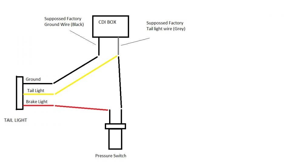
 Brake light Page 2 Harley Davidson Forums From hdforums.com
Grease hose between quick coupler and hydraulic hammer. 220 volt well pump pressure switch wiring diagram. Water enters through normally closed solenoid valve (1) and passes through intake flow meter (2) to high pressure pump (4). Using a low pressure hydraulic brake light switch is your best bet. Diagram 12v hydraulic solenoid valve wiring diagram full version uses of refrigeration low pressure controls industrial controls va7010 8503 c adapter solenoid valve dn15 25 central air. Turn the adjusting screw in the clockwise direction to increase the pressure setting and counterclockwise to decrease pressure.
Loosen the locknut on the pressure switch.
Caution do this at your own risk. Hydraulic power brake (hpb) system for trucks, tractors and buses. John deere 8100, 8200, 8300, 8400 tractors workshop diagnosis & tests technical manual includes: A simple hydraulic schematic showing apparatus for testing the strength of a hydraulic hose splice. Attach the power supply from the main breaker to the outside terminals marked “line” (l1/l2). Two wires from jack motor to switch.
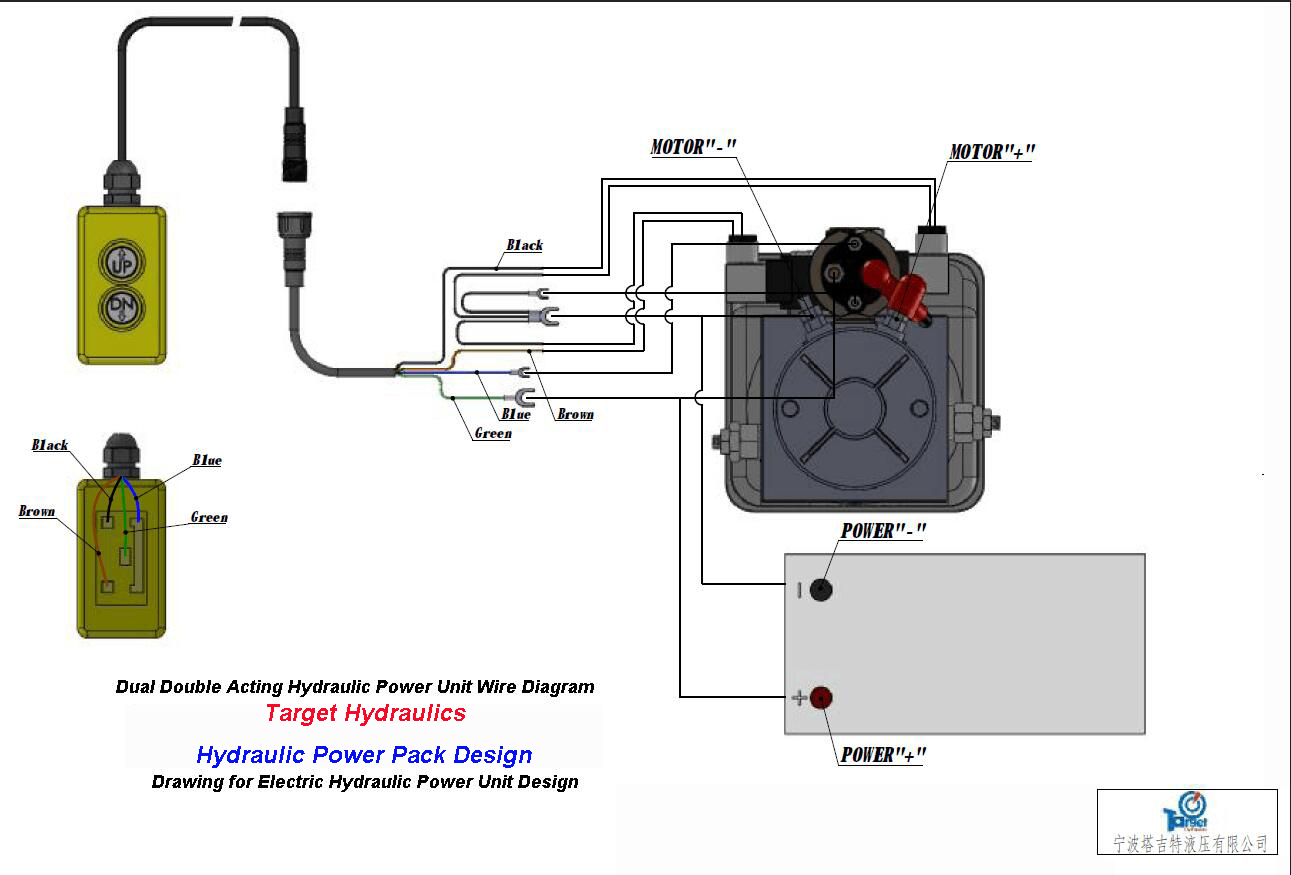
 Source: target-hydraulics.com
Loosen the locknut on the pressure switch. Pressure relief valves are used to limit the maximum pressure in all or part of the hydraulic system. Grease hose between quick coupler and hydraulic hammer. This allows hydraulic fluid to enter the top chamber of the piston and drive it down. Pressure reducing valves are used to reduce the pressure in individual circuits.
 Source: yourmechanic.com
John deere 8100, 8200, 8300, 8400 tractors workshop diagnosis & tests technical manual includes: This video explains how to test a 1 prong and 2 prong pressure switch. A 12v dc electric motor drives a hydraulic pump that moves fluid through a system of hoses, fittings and jacks to level and stabilize the coach. Parking brake pressure supply valve 85 installation parking brake pressure supply valve 87 removal low pressure hose 88 installation Pressure switches are use to detect a pressure rise or fall through a set pressure point.
 Source: diagramweb.net
It reveals the parts of the circuit as simplified forms and the power as well as signal connections. It reveals the parts of the circuit as simplified forms and the power as well as signal connections. Attach the ground wire to the green ground screw. Wiring of the solenoid valve is simple. Brake light pressure switch wiring diagram.
 Source: gambarlah.wordpress.com
Pressure reducing valves are used to reduce the pressure in individual circuits. Oil cannot flow from 2 to 1. Attach the ground wire to the green ground screw. The brake pressure switchs should never see 12v. System warning failure to act in accordance with the following may result in serious personal injury or death.
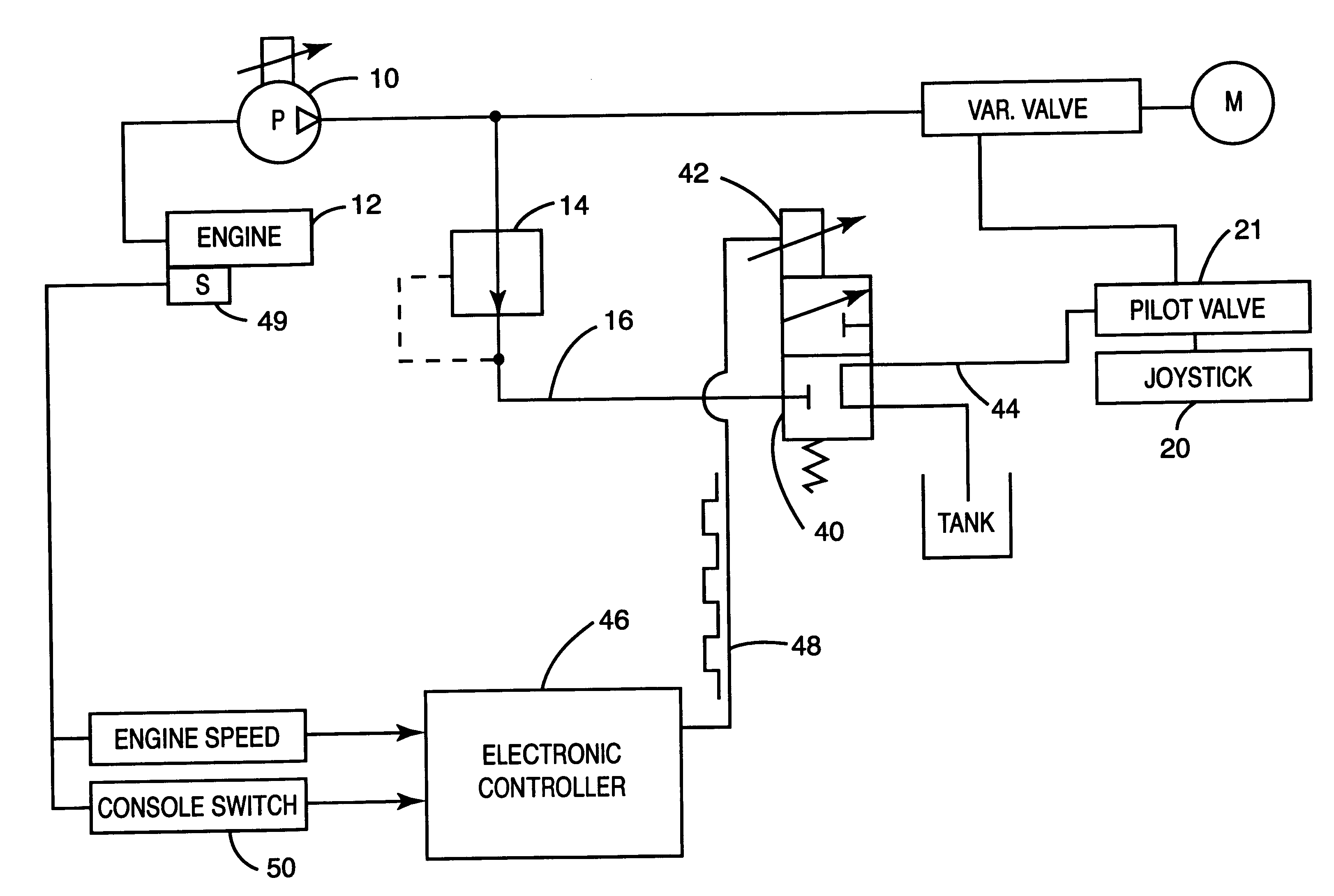
 Source: youtube.com
Find great deals on ebay for 12 volt air pressure switch. Loosen the locknut on the pressure switch. This applies also to the drawings and diagrams appended. This video explains how to test a 1 prong and 2 prong pressure switch. Wiring diagram hpb wiring diagram for multiplex vehicles.
 Source: summit-hydraulics.com
Attach the ground wire to the green ground screw. J2 t t 2 j5 j1 1 on 1 on 2 k1 k4 gnd 24v c4 pendant switch power switch 4 115 v neutral ground j3 j4 6 5 vio. Brake light wiring diagram this brake light wiring diagram gives you a clear picture of where each wire goes. These switches may or may not be adjustable. John deere 8100, 8200, 8300, 8400 tractors workshop diagnosis & tests technical manual includes:
 Source: gambarlah.wordpress.com
Pressure switch features lippert lci hydraulic jack system failure and how to solve for rv and fifth wheel trailers. When pressure is lost in either the. Diagram motorhome jacks hydraulic wiring ygstup infinityagespa it. Brake light wiring diagram this brake light wiring diagram gives you a clear picture of where each wire goes. John deere 8100, 8200, 8300, 8400 tractors workshop diagnosis & tests technical manual includes:
 Source: schematron.org
The differential pressure switch reacts to a loss of master cylinder hydraulic pressure in either side of the split hydraulic system and can illuminate a warning light at the instrument panel. The brake pressure switchs should never see 12v. A 12v dc electric motor drives a hydraulic pump that moves fluid through a system of hoses, fittings and jacks to level and stabilize the coach. Test the pressure switch for several cycles to ensure that it is working properly. This allows hydraulic fluid to enter the top chamber of the piston and drive it down.
 Source: ricardolevinsmorales.com
Pmax = 180bar as long as p<pmax, oil flows from. Parking brake pressure supply valve 85 installation parking brake pressure supply valve 87 removal low pressure hose 88 installation Humbucker wiring diagram 3 way switch dimarzio pickup wiring diagram 7 pin flat trailer connector diagram The use of the lippert electronic leveling system to support the coach for any reason. Wiring diagram hpb wiring diagram for multiplex vehicles.
 Source: ricardolevinsmorales.com
Grease pressure switch for monitoring the minimum required grease pressure (20 bar) per greasing cycle. The lippert smart jack on my travel trailer stopped working because the circuitmemory board failed. 49 average based on 8 product ratings. 220 volt well pump pressure switch wiring diagram. This allows hydraulic fluid to enter the top chamber of the piston and drive it down.
 Source: thumpertalk.com
System warning failure to act in accordance with the following may result in serious personal injury or death. If 1,500 psi is required to run a hydraulic motor and the system pressure drop is 500 psi, the operating pressure measured at the pump will be 2,000 psi. Diagram 12v hydraulic solenoid valve wiring diagram full version uses of refrigeration low pressure controls industrial controls va7010 8503 c adapter solenoid valve dn15 25 central air. Brake light pressure switch wiring diagram. The brake pressure switchs should never see 12v.
 Source: untpikapps.com
Brake light pressure switch wiring diagram. Tusk hydraulic brake switch instructions the tusk hydraulic brake switch can be used on a variety of machines with brembo and nissin master cylinders. When the piston is fully retracted and hydraulic pressure builds, the unloader (relief) valve will lift and maintain the system’s pressure at setpoint. Pressure switch features lippert lci hydraulic jack system failure and how to solve for rv and fifth wheel trailers. The lippert electronic leveling and slideout system is an electric/hydraulic system.
 Source: kovodym.blogspot.com
Complete diagnosis & tests technical manual with electrical wiring diagrams for john deere 2wd or mfwd tractors 8100, 8200, 8300, 8400, with all the shop information to maintain, diagnose, and service like professional mechanics. When pressure is lost in either the. These switches may or may not be adjustable. Turn the adjusting screw in the clockwise direction to increase the pressure setting and counterclockwise to decrease pressure. Set the motor control toggle switch on run.
 Source: hdforums.com
Connect the pump power supply and place the control valve in the advance position. Tusk hydraulic brake switch instructions the tusk hydraulic brake switch can be used on a variety of machines with brembo and nissin master cylinders. Intake water pressure is monitored by pressure gauge (3). The lippert smart jack on my travel trailer stopped working because the circuitmemory board failed. Wiring of the solenoid valve is simple.
 Source: worldvisionsummerfest.com
Humbucker wiring diagram 3 way switch dimarzio pickup wiring diagram 7 pin flat trailer connector diagram Pmax = 180bar as long as p<pmax, oil flows from. The lippert electronic leveling and slideout system is an electric/hydraulic system. Set the motor control toggle switch on run. A simple hydraulic schematic showing apparatus for testing the strength of a hydraulic hose splice.
 Source: wiringdiagram.2bitboer.com
Relief valve (300 bar) with return channel to the grease reservoir and. Brake light wiring diagram this brake light wiring diagram gives you a clear picture of where each wire goes. Hydraulic power brake (hpb) system for trucks, tractors and buses. The workshop manual includes repair and service manuals, information for the scheduled time of repair, maintenance instructions, a complete description of repair and troubleshoots procedures for the skeed steer loaders new holland ls160 and ls170. Oil cannot flow from 2 to 1.
 Source: schematron.org
A simple hydraulic schematic showing apparatus for testing the strength of a hydraulic hose splice. The differential pressure switch reacts to a loss of master cylinder hydraulic pressure in either side of the split hydraulic system and can illuminate a warning light at the instrument panel. Pressure reducing valves are used to reduce the pressure in individual circuits. Two wires from jack motor to switch. Attach the power supply from the main breaker to the outside terminals marked “line” (l1/l2).
 Source: tonetastic.info
Attach the ground wire to the green ground screw. John deere 8100, 8200, 8300, 8400 tractors workshop diagnosis & tests technical manual includes: Wiring diagram hpb wiring diagram for multiplex vehicles. If 1,500 psi is required to run a hydraulic motor and the system pressure drop is 500 psi, the operating pressure measured at the pump will be 2,000 psi. 220 volt well pump pressure switch wiring diagram.
This site is an open community for users to do submittion their favorite wallpapers on the internet, all images or pictures in this website are for personal wallpaper use only, it is stricly prohibited to use this wallpaper for commercial purposes, if you are the author and find this image is shared without your permission, please kindly raise a DMCA report to Us.
If you find this site serviceableness, please support us by sharing this posts to your preference social media accounts like Facebook, Instagram and so on or you can also bookmark this blog page with the title hydraulic pressure switch wiring diagram by using Ctrl + D for devices a laptop with a Windows operating system or Command + D for laptops with an Apple operating system. If you use a smartphone, you can also use the drawer menu of the browser you are using. Whether it’s a Windows, Mac, iOS or Android operating system, you will still be able to bookmark this website.
Category
Related By Category
- Predator 670 engine wiring diagram Idea
- Frsky x8r wiring diagram information
- Pioneer ts wx130da wiring diagram Idea
- Johnson 50 hp wiring diagram Idea
- Kohler voltage regulator wiring diagram Idea
- Johnson 50 hp outboard wiring diagram information
- Kti hydraulic remote wiring diagram Idea
- Pyle plpw12d wiring diagram information
- Tx9600ts wiring diagram information
- Lifan 50cc wiring diagram information