Hvac relay wiring diagram Idea
Home » Trend » Hvac relay wiring diagram Idea
Your Hvac relay wiring diagram images are available in this site. Hvac relay wiring diagram are a topic that is being searched for and liked by netizens today. You can Find and Download the Hvac relay wiring diagram files here. Find and Download all free photos and vectors.
If you’re searching for hvac relay wiring diagram images information related to the hvac relay wiring diagram interest, you have pay a visit to the ideal site. Our site always gives you suggestions for seeing the highest quality video and image content, please kindly hunt and find more enlightening video content and images that fit your interests.
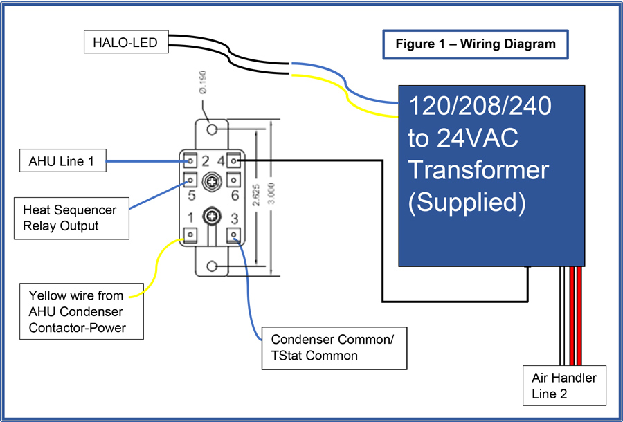
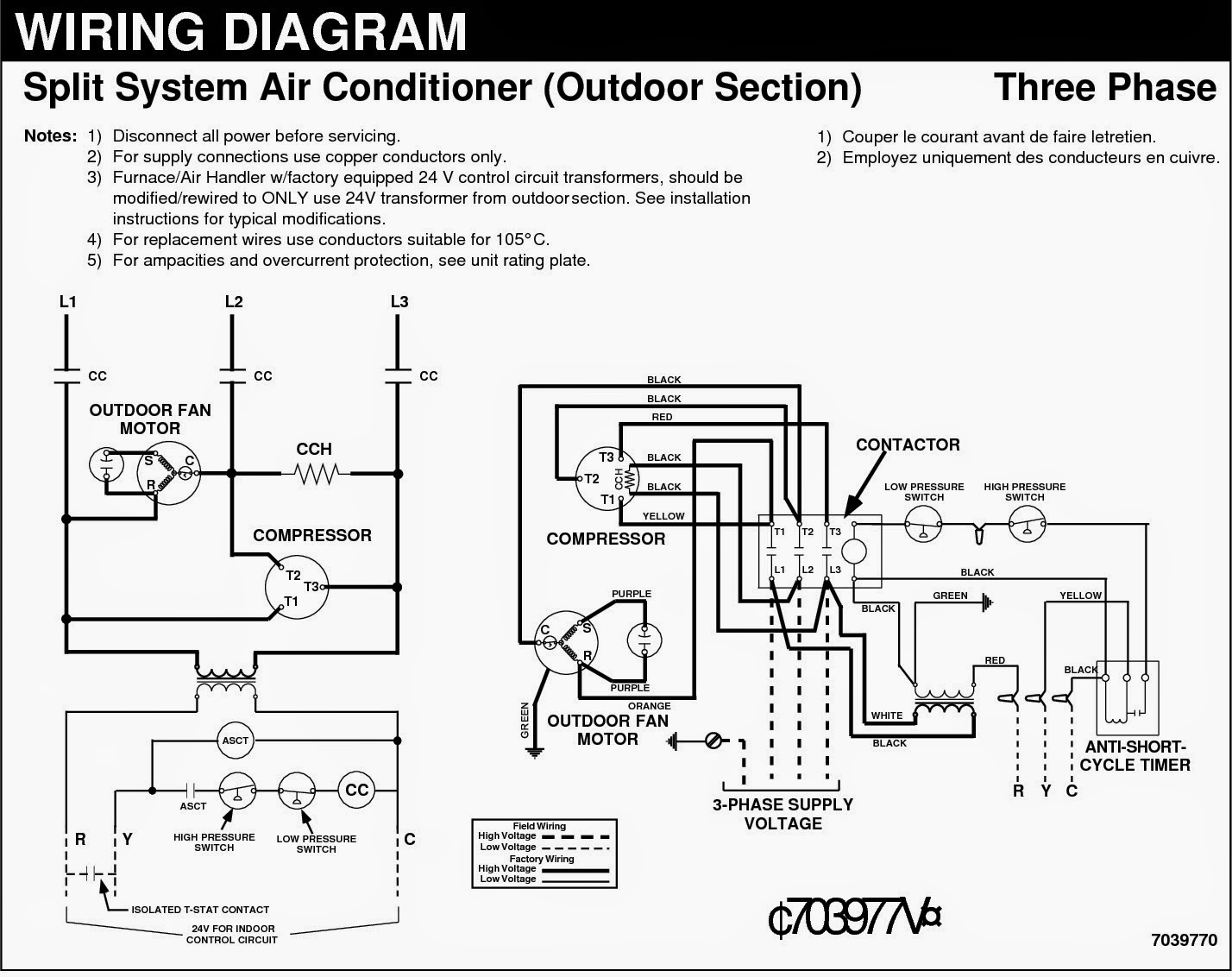
Hvac Relay Wiring Diagram. Use copper wire (75ºc min) only between disconnect switch and unit. 12 dual electric fan relay wiring diagram wiring diagram wiringg net in 2020 electric cooling fan electric radiator fan diagram relay internal wiring diagram new wiring diagram indoor blower motor. Pin 87 = yellow wire pin 85 = orange wire pin 86 = grey wire pin 30 = red wire. I demonstrate how easy it is to use the wiring diagram to figure out where the wires go.attention:
 Goodman Fan Relay Wiring Diagram Wiring Diagram From wiringdiagram.2bitboer.com
Electric fan relay wiring diagram wiring diagram is a simplified tolerable pictorial representation of an electrical circuit it shows the components of the circuit as simplified shapes and the capability and signal contacts between the devices. Thermostat wiring configurations customer support blower motor circuit diagram 2004 2009 3 5l chevy malibu and relay switch instructions rgf 11 best century condenser fan motor wiring diagram ideas 50 luxury air handler fan relay wiring diagram ac wiring thermostat wiring diagrams quality hvac. These lines far exceed the 120 volts ac standard in most homes. A wiring diagram is a simplified traditional pictorial representation of an electrical circuit. Hvac fan relay wiring diagram. Wiring diagram for a relay switch save wiring diagram ac valid hvac.
Also typical ground trigger trinary switch connection shown.
Hvac wiring diagrams 101.rheem ruud hvac age manuals parts connecting thermostat on heat pump dual compressor condensing unit diagram ac wiring full air conditioner for control 5 wires old handler new contactor diy chart honeywell t stat l rpka 019 jaz plump rheem ruud hvac age manuals parts lists wiring diagrams free pdf s connecting. It contains instructions and diagrams for various kinds of wiring strategies along with other things like lights, windows, and so forth. It contains guidelines and diagrams for different kinds of wiring strategies and other products like lights, windows, and so forth. Control wiring new basic hvac control wiring schema wiring diagram thebrontes co unique co in 2020 electrical circuit diagram basic electrical wiring circuit diagram the first and most common is the ladder diagram so called because it looks like the symbols that are used to represent the components in the system have been placed on the rungs of. Wiring diagram hvac valid diagram for a unique hvac diagram best. Interface arduino 5v relay and control ac appliances.
 Source: worldvisionsummerfest.com
Hvac fan relay wiring diagram. Single fan wiring diagram (orange wire) 10 gauge wire 12 gauge wire relay detail: To be wired in accordance with n.e.c. Relay 2 22 vdc coil rec relay 3 22 vdc coil 58 idr blu orn orn 1 /3 field convertible blk/wht red/wht seenote#4 for 3 phase wiring denotes wire to be moved for 3 phase conversion. There are different kinds of relays for different purposes.
 Source: hvacrschool.com
Disconnect blue wire from relay 1 terminal 6, cut, strip, and connect to field wire l3. Control wiring new basic hvac control wiring schema wiring diagram thebrontes co unique co in 2020 electrical circuit diagram basic electrical wiring circuit diagram the first and most common is the ladder diagram so called because it looks like the symbols that are used to represent the components in the system have been placed on the rungs of. We, again, feed the ac relay the ac voltage it is rated for. Ac relay wiring diagram a c clutch function and troubleshooting ford escape ricks free auto repair advice automotive tips how to air conditioner compressor solution. If any of the original wire, as supplied, must be replaced, use the same or equivalent type wire.
 Source: ricardolevinsmorales.com
Use copper wire (75ºc min) only between disconnect switch and unit. I suspected a bad relay switch within the circuit board. Hvac fan relay wiring diagram. Relay switch wiring diagram ac. Hvac fan relay wiring diagram.
 Source: faceitsalon.com
Replacement for rbm style 91 relays of the same specifications. The square relay pinout shows how the relay socket […] 12 dual electric fan relay wiring diagram wiring diagram wiringg net in 2020 electric cooling fan electric radiator fan diagram relay internal wiring diagram new wiring diagram indoor blower motor. Electric fan relay wiring diagram wiring diagram is a simplified tolerable pictorial representation of an electrical circuit it shows the components of the circuit as simplified shapes and the capability and signal contacts between the devices. Red white wire at ac switch microswitch in dash.
 Source: keywordteam.net
Thermostat wiring configurations customer support blower motor circuit diagram 2004 2009 3 5l chevy malibu and relay switch instructions rgf 11 best century condenser fan motor wiring diagram ideas 50 luxury air handler fan relay wiring diagram ac wiring thermostat wiring diagrams quality hvac. Heat pumps are different than air conditioners because a heat pump uses the process of refrigeration to heat and cool.while an air conditioner uses the process of refrigeration to only cool, the central air conditioner will usually be paired with a gas furnace, an electric furnace, or some other. If any of the original wire, as supplied, must be replaced, use the same or equivalent type wire. Air conditioner relay diagram 85 87 86 30 orange wire: Trane heat pump wiring trane heat pump thermostat installation thermostat wiring.
 Source: wiringdiagramall.blogspot.com
I demonstrate how easy it is to use the wiring diagram to figure out where the wires go.attention: When the thermostat calls for the hvac system to run, the g wire will now be carrying the 24 volts (control voltage) to the indoor blower motor relay/contactor coil. Electric fan relay wiring diagram wiring diagram is a simplified tolerable pictorial representation of an electrical circuit it shows the components of the circuit as simplified shapes and the capability and signal contacts between the devices. Wiring diagram for a relay switch save wiring diagram ac valid hvac. Wiring a fan relay by yourself can be a tricky task;
 Source: dentistmitcham.com
A wiring diagram is a simplified conventional photographic depiction of an electrical circuit. It can be used as a fan relay, pump relay or blower relay and. Wiring diagram 2 wire heating cooling thermostat 8 s 3. The diagram above is the 5 pin relay wiring diagram. Hvac fan relay wiring diagram download.
 Source: keywordteam.net
Trane heat pump wiring trane heat pump thermostat installation thermostat wiring. I suspected a bad relay switch within the circuit board. Trane heat pump wiring trane heat pump thermostat installation thermostat wiring. Schematic symbols 2 for how to read a wiring diagram hvac wiring hvac system circuit diagram hvac. Hvac wiring diagram you will need an extensive skilled and easy to know wiring.
 Source: wiringdiagram.2bitboer.com
I do have a wiring diagram however this one is not showing a connection between the auxiliary fan relay and the mas relaythe reason why i need it is because the diagram i have shows me 5 wires comming out of the auxiliary relay and checking it there. Heat pumps are different than air conditioners because a heat pump uses the process of refrigeration to heat and cool.while an air conditioner uses the process of refrigeration to only cool, the central air conditioner will usually be paired with a gas furnace, an electric furnace, or some other. Wiring diagram contactor and overload wiring diagram technic contactor relay wiring wiring diagram datasource. Pin 87 = yellow wire pin 85 = orange wire pin 86 = grey wire pin 30 = red wire. In order to understand wiring diagrams, we need to understand the main components and their differences.
 Source: dentistmitcham.com
It can be used as a fan relay, pump relay or blower relay and. Collection of nordyne thermostat wiring diagram. Relay switch wiring diagram ac. G is connected to one side of the coil (think l1 on a wiring diagram), and the other side is connected to neutral (think l2). We, again, feed the ac relay the ac voltage it is rated for.
 Source: wiringdiagram.2bitboer.com
Relay 2 22 vdc coil rec relay 3 22 vdc coil 58 idr blu orn orn 1 /3 field convertible blk/wht red/wht seenote#4 for 3 phase wiring denotes wire to be moved for 3 phase conversion. It contains instructions and diagrams for various kinds of wiring strategies along with other things like lights, windows, and so forth. It can be used for various switching. Loads perform work and draw amperage. Assortment of electric furnace fan relay wiring diagram.
 Source: worldvisionsummerfest.com
Also typical ground trigger trinary switch connection shown. By len naidoo | march 18, 2018. Pin 87 = yellow wire pin 85 = orange wire pin 86 = grey wire pin 30 = red wire. Higginbotham on saturday, february 9th, 2019 in category wiring diagram. Air conditioner relay diagram 85 87 86 30 orange wire:
 Source: diagramweb.net
To a/c compressor wire/trinary switch vehicle ground red wire: The square relay pinout shows how the relay socket […] Pin 87 = yellow wire pin 85 = orange wire pin 86 = grey wire pin 30 = red wire. If not, the arrangement won’t function as it ought to be. G is connected to one side of the coil (think l1 on a wiring diagram), and the other side is connected to neutral (think l2).
 Source: tops-stars.com
To a/c compressor wire/trinary switch vehicle ground red wire: Hvac fan relay wiring diagram download. Wiring diagram for a relay switch save wiring diagram ac valid hvac. By len naidoo | march 18, 2018. This basic wiring diagram includes all three main parts, power supply, switch and load.
 Source: worldvisionsummerfest.com
Schematic symbols 2 for how to read a wiring diagram hvac wiring hvac system circuit diagram hvac. Learning to read wiring diagrams. Blower motor relay wiring diagram. Fan relay wiring diagram hvac. Wiring diagram contactor and overload wiring diagram technic contactor relay wiring wiring diagram datasource.
 Source: 2020cadillac.com
The hvac fan relay wiring diagram, in particular, can help you if you want to do the job yourself. Hvac blower motor relay wiring diagram. To a/c compressor wire/trinary switch vehicle ground red wire: Hvac wiring diagrams 101.rheem ruud hvac age manuals parts connecting thermostat on heat pump dual compressor condensing unit diagram ac wiring full air conditioner for control 5 wires old handler new contactor diy chart honeywell t stat l rpka 019 jaz plump rheem ruud hvac age manuals parts lists wiring diagrams free pdf s connecting. I demonstrate how easy it is to use the wiring diagram to figure out where the wires go.attention:
Source: schematicandwiringdiagram.blogspot.com
These lines far exceed the 120 volts ac standard in most homes. Loads perform work and draw amperage. I suspected a bad relay switch within the circuit board. We, again, feed the ac relay the ac voltage it is rated for. Wiring a fan relay by yourself can be a tricky task;
 Source: kovodym.blogspot.com
Also typical ground trigger trinary switch connection shown. Hvac fan relay wiring diagram download. See also best way to wash face cloths. The best free hvac drawing images from 73 drawings. Wiring a fan relay by yourself can be a tricky task;
This site is an open community for users to share their favorite wallpapers on the internet, all images or pictures in this website are for personal wallpaper use only, it is stricly prohibited to use this wallpaper for commercial purposes, if you are the author and find this image is shared without your permission, please kindly raise a DMCA report to Us.
If you find this site helpful, please support us by sharing this posts to your favorite social media accounts like Facebook, Instagram and so on or you can also save this blog page with the title hvac relay wiring diagram by using Ctrl + D for devices a laptop with a Windows operating system or Command + D for laptops with an Apple operating system. If you use a smartphone, you can also use the drawer menu of the browser you are using. Whether it’s a Windows, Mac, iOS or Android operating system, you will still be able to bookmark this website.
Category
Related By Category
- Predator 670 engine wiring diagram Idea
- Frsky x8r wiring diagram information
- Pioneer ts wx130da wiring diagram Idea
- Johnson 50 hp wiring diagram Idea
- Kohler voltage regulator wiring diagram Idea
- Johnson 50 hp outboard wiring diagram information
- Kti hydraulic remote wiring diagram Idea
- Pyle plpw12d wiring diagram information
- Tx9600ts wiring diagram information
- Lifan 50cc wiring diagram information