Hvac float switch wiring diagram information
Home » Trending » Hvac float switch wiring diagram information
Your Hvac float switch wiring diagram images are available in this site. Hvac float switch wiring diagram are a topic that is being searched for and liked by netizens now. You can Download the Hvac float switch wiring diagram files here. Find and Download all free vectors.
If you’re looking for hvac float switch wiring diagram images information linked to the hvac float switch wiring diagram interest, you have come to the ideal site. Our website frequently gives you suggestions for refferencing the highest quality video and picture content, please kindly search and locate more enlightening video articles and graphics that match your interests.
Hvac Float Switch Wiring Diagram. Luxury wiring diagram combi boiler diagrams digramssample diagramimages wiringdiagramsample wiringdiagram ch electrical wiring diagram steam boiler boiler. A float switch is essentaially an electronic water sensor for your hvac system. You do not want to blow fuses and yes, 24 volts hurts too. Tunr the power off to the furnace by the breaker or switch if you have one, not just stat off.
 Float Switch Installation Wiring And Control Diagrams APG From apgsensors.com
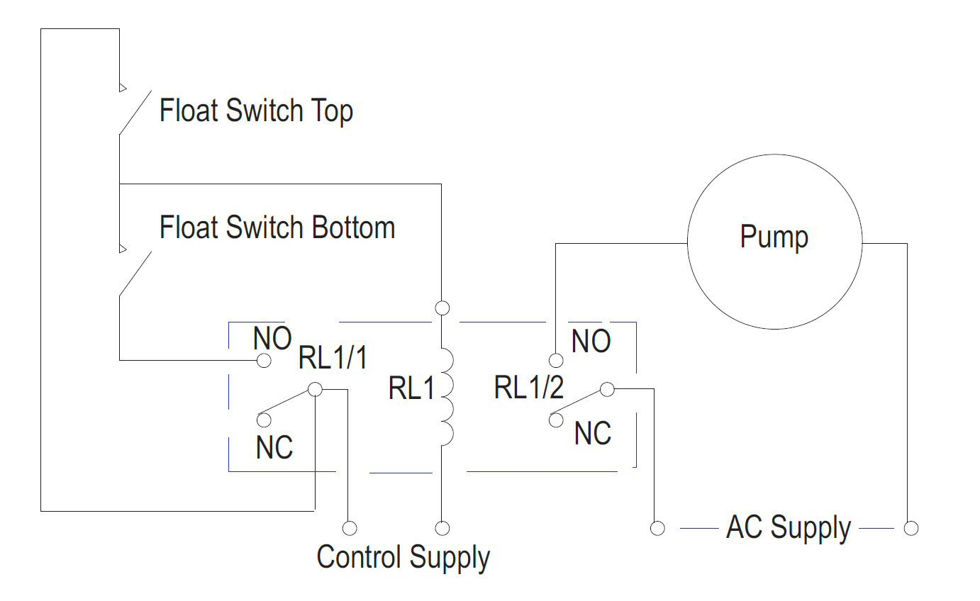
Float switch is basically is the combination of no and nc circuit that changes its contacts depends upon the alignment at which it is placed. We have 12 models about water float switch wiring diagram including images, pictures, models, photos, and much more. An open switch has no electrical path, meaning that the equipment can�t turn on. Red wire / white stripe to qc1a, blk wire / white stripe to qc2a. Twist one end of each float switch wire to one of the exposed section of the cut r terminal wire. Hvac float switch wiring diagram.
Condensate drain pan float switch wiring diagram.
The electrical wire needs to be fixed in a position that isn’t going to change the depth of the float switch, as seen in figure 2. With this sort of an illustrative manual, you will have the ability to troubleshoot, avoid, and full your assignments without difficulty. Subsequently a pain to remove, replace or repair the wiring in an automobile, having an accurate and detailed ac float switch wiring. The air conditioner absorbs the heat in. Red wire / white stripe to qc1a, blk wire / white stripe to qc2a. Typical float switches are normally resting in the closed position, meaning the circuit is incomplete and no electricity is passing through.
 Source: kelvin-okl.blogspot.com
If the air handler is installed vertically, most of the time it is installed on the front of the air handler itself next to where the primary condensate drain exits the unit. Subsequently a pain to remove, replace or repair the wiring in an automobile, having an accurate and detailed ac float switch wiring. Older float switches work by opening and closing circuits (dry contacts) as water levels rise and fall. The wiring diagram is right on it. How to read ac schematics and diagrams basics.
 Source: kelvin-okl.blogspot.com
An open switch has no electrical path, meaning that the equipment can�t turn on. There will be three diagrams: Those schematics show various types of switches, including basic switches, pressure switches, thermal switches, float switches, and contacts. What it does it gives your ac system the ability to detect if it has a clogged drain, and if the switch detects a clogged drain scenario, it immediately shuts the system off. A float switch is essentaially an electronic water sensor for your hvac system.
 Source: mikrora.com
How to wire an air conditioner for control 5 wires the diagram below includes the typical control wiring for a conventional central air conditioning systemfurthermore it includes a thermostat a condenser and an air handler with a heat source. Condensate drain pan float switch wiring diagram. One of the wires from the float switch to one side of cut wire and the other end of the float switch wire to the other. A float switch is essentaially an electronic water sensor for your hvac system. A float switch consists of the floating switch and the electrical wire.
 Source: kelvin-okl.blogspot.com
Replacement household furnace control circuit boards. 240v single pole thermostat wiring diagram. Ac switch wiring diagram.a wiring diagram is a streamlined standard photographic representation of an electric circuit. Senasys manufacturers a variety of snap action switches for hvac systems in addition to our temperature and pneumatic switches. Those schematics show various types of switches, including basic switches, pressure switches, thermal switches, float switches, and contacts.
 Source: primagem.org
220v 3 wire well pump wiring diagram. 43 testing and analysis 62. How to read ac schematics and diagrams basics. Ac switch wiring diagram.a wiring diagram is a streamlined standard photographic representation of an electric circuit. Whenever you approach a wiring diagram, look at the whole thing, especially the legend and notes.
 Source: justanswer.com
The float switch may be installed in a few different places. The signal words warning, caution, and In this article, we are going to see float switch connection diagram and wiring. Find this pin and more on h.v.a.c. The air conditioner absorbs the heat in.
 Source: tankbig.com
220v 3 wire well pump wiring diagram. Lets start with the most basic float switch. Replacement household furnace control circuit boards. Condensate drain pan float switch wiring diagram. For example look at the chassis battery is stated as 12v 20ah.
Source: bosco-mylove.blogspot.com
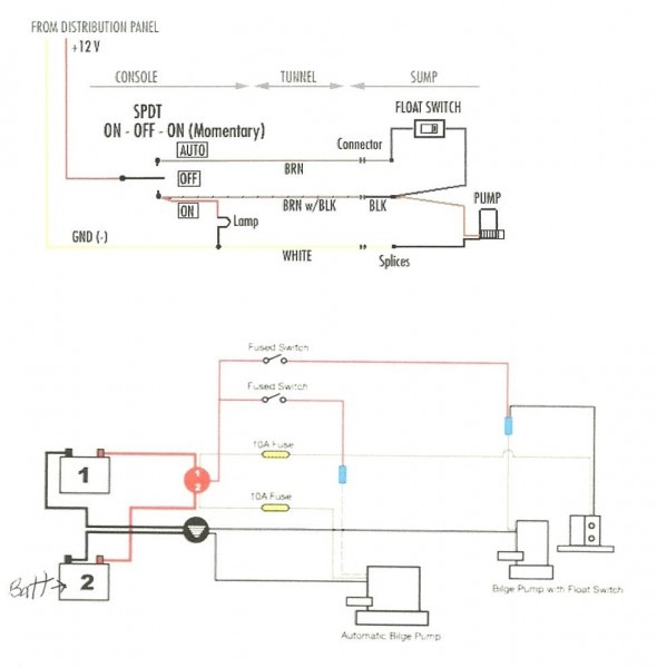
Such as png, jpg, animated gifs, pic art, logo, black and white. The sail actuator detects when air… Most float switches have a float with two wires coming from the top of it where the float can be removed from. Use copper wire (75ºc min) only between disconnect switch and unit. According to earlier the traces in a septic tank float switch wiring diagram signifies wires.

Cut the red r terminal wire running the thermostat with a pair of wire cutters. Ac switch wiring diagram.a wiring diagram is a streamlined standard photographic representation of an electric circuit. 43 testing and analysis 62. Those schematics show various types of switches, including basic switches, pressure switches, thermal switches, float switches, and contacts. Float switch is basically is the combination of no and nc circuit that changes its contacts depends upon the alignment at which it is placed.
Source: kelvin-okl.blogspot.com
In many cases, factory wiring will show up as solid lines and field. The meaning is this can power the currents of 20 amps per hour. In addition in the case of. What it does it gives your ac system the ability to detect if it has a clogged drain, and if the switch detects a clogged drain scenario, it immediately shuts the system off. Guide to connecting the safety on a condensate removal pump for plenum central heating wiring diagrams mini alarm circuit little giant boiler installation sanicondens best with.
Source: wiringdiagram101.blogspot.com
The signal words warning, caution, and Luxury wiring diagram combi boiler diagrams digramssample diagramimages wiringdiagramsample wiringdiagram ch electrical wiring diagram steam boiler boiler. To be wired in accordance with nec and local codes. For example look at the chassis battery is stated as 12v 20ah. Those schematics show various types of switches, including basic switches, pressure switches, thermal switches, float switches, and contacts.
 Source: tankbig.com
Older float switches work by opening and closing circuits (dry contacts) as water levels rise and fall. In many cases, factory wiring will show up as solid lines and field. To be wired in accordance with nec and local codes. 50 push button switch diagram uc9f electricity switch diagram. What it does it gives your ac system the ability to detect if it has a clogged drain, and if the switch detects a clogged drain scenario, it immediately shuts the system off.
 Source: secerahpewarnaa.blogspot.com
Replacement household furnace control circuit boards. The electrical wire needs to be fixed in a position that isn’t going to change the depth of the float switch, as seen in figure 2. Ac switch wiring diagram.a wiring diagram is a streamlined standard photographic representation of an electric circuit. Air conditioners convert liquid to gas, and they use the gas to cool buildings. In many cases, factory wiring will show up as solid lines and field.
 Source: tankbig.com
If any of the original wire, as supplied, must be replaced, use the same or equivalent type wire. 240v single pole thermostat wiring diagram. The wiring diagram is right on it. Cut the red r terminal wire running the thermostat with a pair of wire cutters. It shows the components of the circuit as simplified shapes, and the capability and signal connections along with the devices.
 Source: bulkreefsupply.com
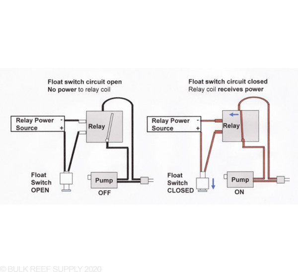
Whenever you approach a wiring diagram, look at the whole thing, especially the legend and notes. The wiring diagram of the knife blade switch is incorrect. Better than a float switch. An open switch has no electrical path, meaning that the equipment can�t turn on. With this sort of an illustrative manual, you will have the ability to troubleshoot, avoid, and full your assignments without difficulty.
Source: kelvin-okl.blogspot.com
Use copper wire (75ºc min) only between disconnect switch and unit. Typical coal power plant thermal power plant thermal power station power engineering. Red wire / white stripe to qc1a, blk wire / white stripe to qc2a. 50 push button switch diagram uc9f electricity switch diagram. 43 testing and analysis 62.
 Source: justanswer.com
The wiring diagram is right on it. Strip 1/2 inch of insulation from each end of the cut terminal wire and the end of each float switch wire with a pair of wire strippers. 220v 3 wire well pump wiring diagram. The wiring diagram is right on it. An open switch has no electrical path, meaning that the equipment can�t turn on.
 Source: apgsensors.com
This circuit can be used to fill a water tank automatically. Hvac float switch wiring diagram. What it does it gives your ac system the ability to detect if it has a clogged drain, and if the switch detects a clogged drain scenario, it immediately shuts the system off. It can either be fixed to a bracket on top of the water tank, or along the side/pipe running down inside the tank. Float switch is basically is the combination of no and nc circuit that changes its contacts depends upon the alignment at which it is placed.
This site is an open community for users to submit their favorite wallpapers on the internet, all images or pictures in this website are for personal wallpaper use only, it is stricly prohibited to use this wallpaper for commercial purposes, if you are the author and find this image is shared without your permission, please kindly raise a DMCA report to Us.
If you find this site good, please support us by sharing this posts to your preference social media accounts like Facebook, Instagram and so on or you can also bookmark this blog page with the title hvac float switch wiring diagram by using Ctrl + D for devices a laptop with a Windows operating system or Command + D for laptops with an Apple operating system. If you use a smartphone, you can also use the drawer menu of the browser you are using. Whether it’s a Windows, Mac, iOS or Android operating system, you will still be able to bookmark this website.
Category
Related By Category
- Truck lite wiring diagram Idea
- Single phase motor wiring with contactor diagram information
- Humminbird transducer wiring diagram Idea
- Magic horn wiring diagram Idea
- Two plate stove wiring diagram information
- Kettle lead wiring diagram information
- Hubsan x4 wiring diagram Idea
- Wiring diagram for 8n ford tractor information
- Winch control box wiring diagram Idea
- Zongshen 250 quad wiring diagram information