Hurst roll control wiring diagram Idea
Home » Trend » Hurst roll control wiring diagram Idea
Your Hurst roll control wiring diagram images are ready in this website. Hurst roll control wiring diagram are a topic that is being searched for and liked by netizens today. You can Find and Download the Hurst roll control wiring diagram files here. Download all free images.
If you’re looking for hurst roll control wiring diagram pictures information connected with to the hurst roll control wiring diagram keyword, you have pay a visit to the ideal site. Our website frequently provides you with suggestions for refferencing the highest quality video and image content, please kindly hunt and find more enlightening video content and graphics that fit your interests.
Hurst Roll Control Wiring Diagram. The hurst roll control solenoid valve is designed for 12v dc operation only. Hurst roll control kit (line lock) can i just install this plane switch or whatever its called instead of the two supplied switches. This gave us some sticks of steel brake line and an assortment of. Electrical wiring obviously has to start and end somewhere.
 Hurst Line Lock Wiring Diagram Wiring Schema From wiringschema101.blogspot.com
This kit comes with all the necessary parts needed to easily install a hurst line/loc system on your mustang. Installed hurst roll control wiring installation note: The fuse can protect the electrical system in the event of a short circuit. Be sure to check all connections the fuse can protect the electrical system in the event of a short circuit. Suggested ground and 12v source: Take the ground wire off the roll control and find a good chasis ground something close to the unit but away from moving parts.
The hurst roll control solenoid valve is designed for 12v dc operation only.
In addition to the b&m launch control kit we also picked up a hurst roll control installation kit (pn 5671510) from summit racing. Short, quick, solid, smooth and precise shift action i need a diagram to show the hurst shifter mechanism. The fuse can protect the electrical system in the event I disliked the large red bulb supplied with the hurst kit so i wired it to light the factory brake idiot. The electrical hookup on a roll control isn’t difficult, but it will take some time to route the wires. I am installing this on just the front brakes so i can hold the front tires with the calipers allowing the rear brakes to remain free.
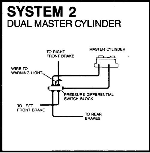 Source: schematron.org
Hurst roll control (line lock) wiring? Short, quick, solid, smooth and precise shift action i need a diagram to show the hurst shifter mechanism. Reconnect battery and test for correct operation. Hurst roll control assemblies have a pair of wires that originate from the solenoid. The take the power wire and run into the passenger compartment, i went in through a rubber boot by the master cylinder but you are on the passenger side of.
 Source: galvinconanstuart.blogspot.com
Take the ground wire off the roll control and find a good chasis ground something close to the unit but away from moving parts. In addition to the b&m launch control kit we also picked up a hurst roll control installation kit (pn 5671510) from summit racing. Short, quick, solid, smooth and precise shift action i need a diagram to show the hurst shifter mechanism. It is normally open, momentary contact, quick release with a maximum 10amp. This will allow you to remove the stock line and tighten slp�s line.
 Source: moritz-usa.blogspot.com
Includes a stainless steel roll/control valve, brake line, fittings, lighted momentary switch, bracket, wiring and much more. In addition to the b&m launch control kit we also picked up a hurst roll control installation kit (pn 5671510) from summit racing. Depress brake pedal and hold, depress control switch and hold, release brake pedal. Following the n) are provided in th wiring recommendation properly will prevent accidental engagement of the hurst roll control system. For added safety, two switches (arming and activatiois kit.
 Source: allfordmustangs.com
This kit comes with all the necessary parts needed to easily install a hurst line/loc system on your mustang. It is a normally open, momentary contact, quick release switch with a maximum 10 amp. Following the n) are provided in th wiring recommendation properly will prevent accidental engagement of the hurst roll control system. Hurst roll control (line lock) wiring? I would like to flick the switch and go straight to engage rather than activating, then depressing the second witch to engage.

It is normally open, momentary contact, quick release with a maximum 10amp. Reconnect battery and test for correct operation. Before connecting the lead wires, cut the ends (that do not have the clip) on a 45° angle. Installed hurst roll control wiring installation note: Hurst roll control assemblies have a pair of wires that originate from the solenoid.
 Source: galvinconanstuart.blogspot.com
The take the power wire and run into the passenger compartment, i went in through a rubber boot by the master cylinder but you are on the passenger side of. A hurst roll control with stainless steel valve. Electrical wiring obviously has to start and end somewhere. Hurst roll control (line lock) wiring? Hurst roll control wiring diagram.
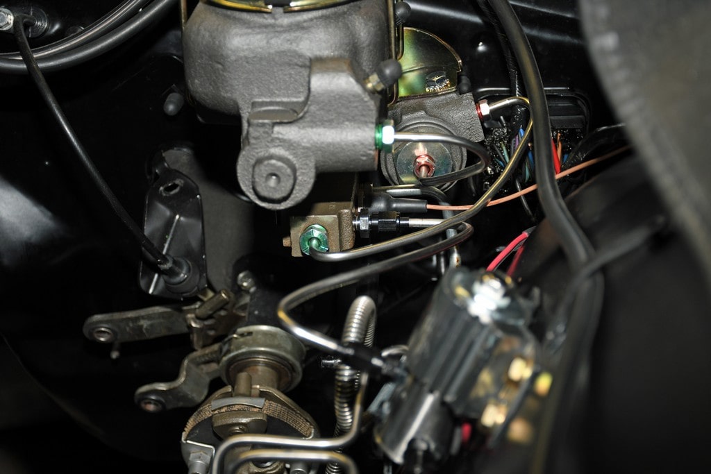 Source: kovodym.blogspot.com
The hurst roll control solenoid valve is designed for 12v dc operation only. Depress brake pedal and hold, depress control switch and hold, release brake pedal. Mine didnt work, so i took it apart, and found the 2 roll pins were broken. The red wire is hot and eventually goes to the switch. Slide the clips onto the spade connectors and cover with the dust boot.
 Source: racingjunk.com
Hurst roll control kit (line lock) can i just install this plane switch or whatever its called instead of the two supplied switches. I�m electrically challenged, but the way i read the instructions the momentary switch light is supposed to come on when you turn on the rocker switch. Hurst roll control kit (line lock) can i just install this plane switch or whatever its called instead of the two supplied switches. Wire per diagram on next page. The fuse can protect the electrical system in the event of a short circuit.
 Source: racingjunk.com
Depress brake pedal and hold, depress control switch and hold, release brake pedal. The fuse can protect the electrical system in the event For added safety, two switches (arming and activation) are provided in this kit. 13mm line wrench long and an open end 13 mm wrench long. Following the n) are provided in th wiring recommendation properly will prevent accidental engagement of the hurst roll control system.
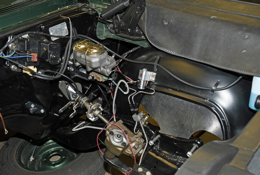 Source: kovodym.blogspot.com
Depress brake pedal and hold, depress control switch and hold, release brake pedal. It is normally open, momentary contact, quick release with a maximum 10amp. Rigorous testing has proved a 1/100,000 of a second release time and vibration tests have seen up to 30 g�s. I disliked the large red bulb supplied with the hurst kit so i wired it to light the factory brake idiot. See “hurst roll control operation” for competiton use caution:
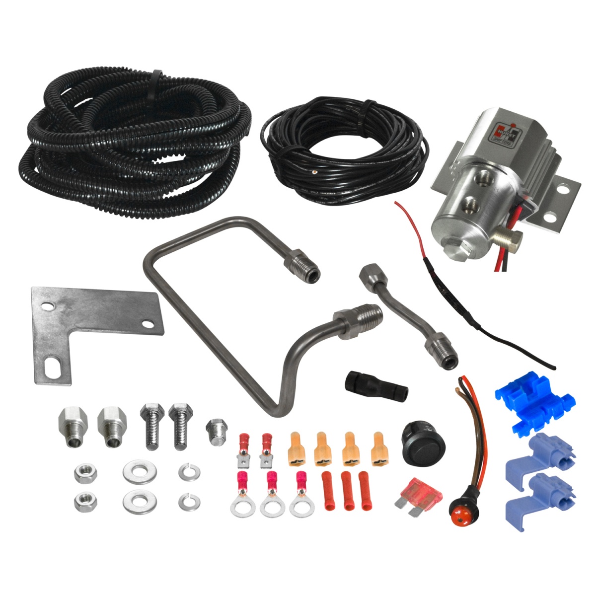 Source: threepedals.com
The fuse can protect the electrical system in the event The take the power wire and run into the passenger compartment, i went in through a rubber boot by the master cylinder but you are on the passenger side of. It is normally open, momentary contact, quick release with a maximum 10amp. Following the wiring recommendation properly will prevent accidental engagement of the hurst roll control system. For added safety, two switches (arming and activation) are provided in this kit.
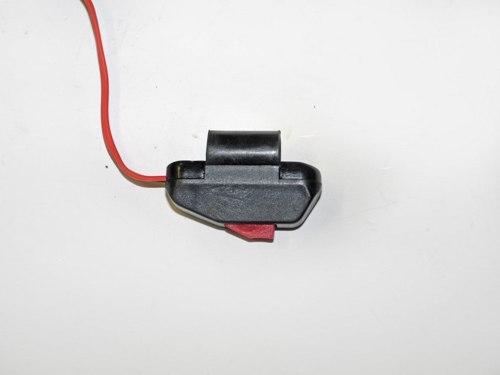 Source: racingjunk.com
The fuse can protect the electrical system in the event of a short circuit. Be sure to check all connections the fuse can protect the electrical system in the event of a short circuit. Mine didnt work, so i took it apart, and found the 2 roll pins were broken. In addition to the b&m launch control kit we also picked up a hurst roll control installation kit (pn 5671510) from summit racing. The fuse can protect the electrical system in the event of a short circuit.
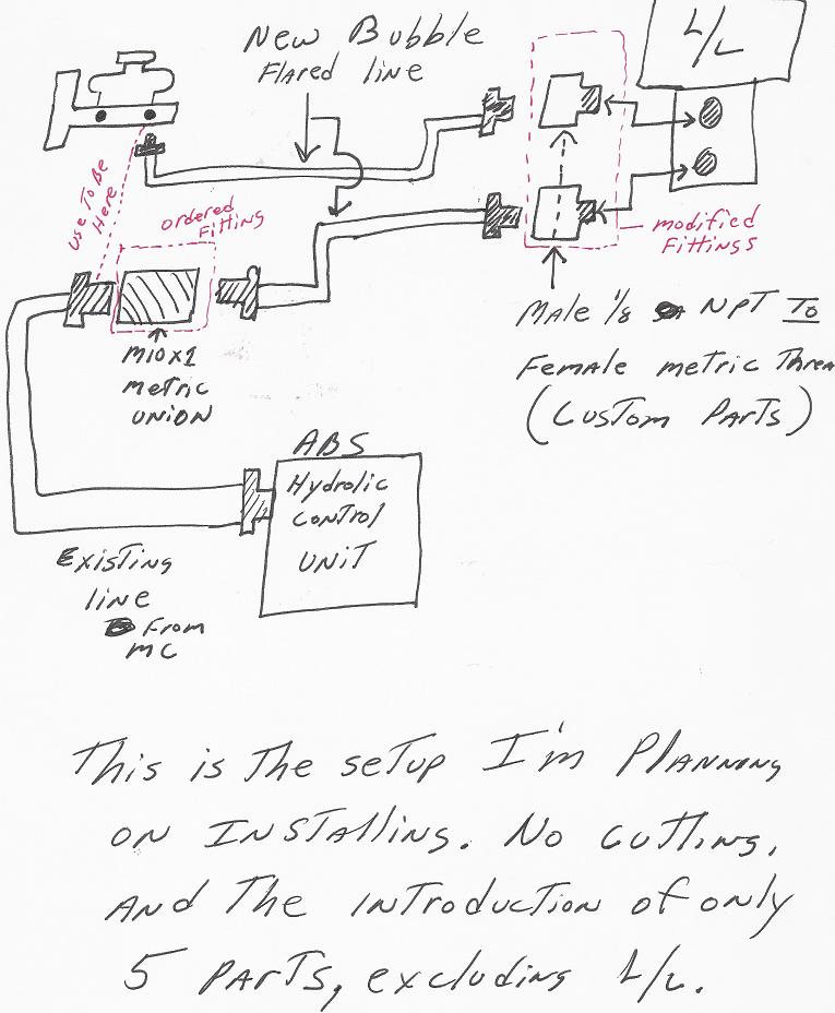 Source: modularfords.com
(see wiring diagram for wiring details) and should be incorporated into the wiring circuit. Below is a picture of my hurst line lock and a diagram of how i wired it. The hurst roll control solenoid valve is designed for 12v dc operation only. The electrical hookup on a roll control isn’t difficult, but it will take some time to route the wires. A hurst roll control with stainless steel valve.

(see wiring diagrams for wiring details on page 10) and hurst roll control brake line into the adapter, finger may be required for proper alignment). The place to begin is the solenoid. For added safety, two switches (arming and activatiois kit. This kit comes with all the necessary parts needed to easily install a hurst line/loc system on your mustang. The red wire is hot and eventually goes to the switch.

Hurst roll control wiring diagram. For added safety, two switches (arming and activatiois kit. (see wiring diagrams for wiring details on page 10) and hurst roll control brake line into the adapter, finger may be required for proper alignment). Take the ground wire off the roll control and find a good chasis ground something close to the unit but away from moving parts. For added safety, two switches (arming and activatiois kit.
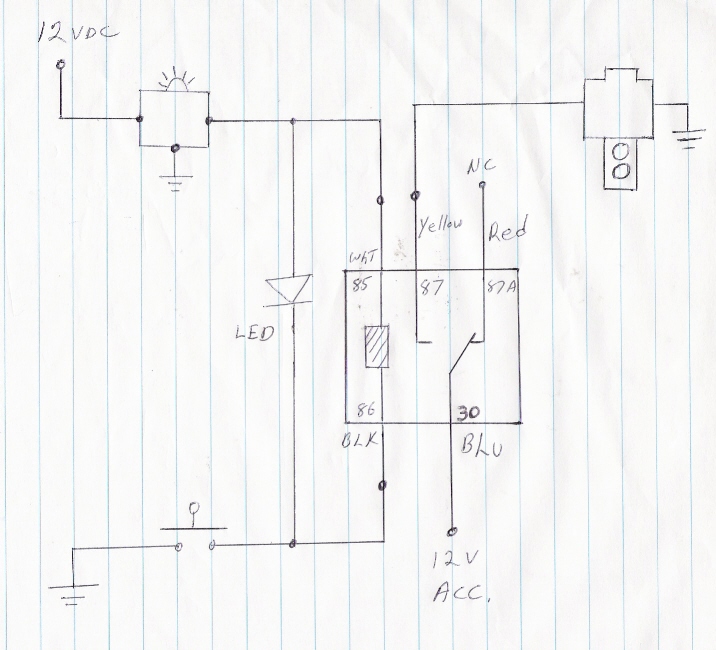 Source: schematron.org
Rigorous testing has proved a 1/100,000 of a second release time and vibration tests have seen up to 30 g�s. Hurst roll control assemblies have a pair of wires that originate from the solenoid. Suggested ground and 12v source: Hurst universal roll control 1745000. Slide the clips onto the spade connectors and cover with the dust boot.
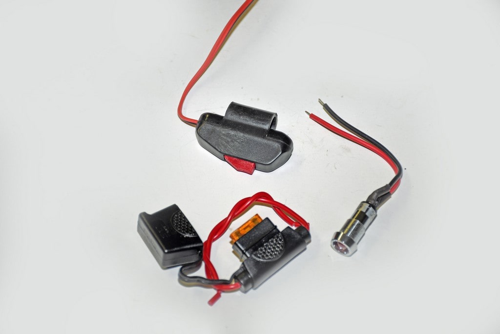 Source: racingjunk.com
The hurst roll control solenoid valve is designed for 12v dc operation only. Connect one lead of the brake light pressure switch to a 12 volt, 15 amp Before connecting the lead wires, cut the ends (that do not have the clip) on a 45° angle. Installed hurst roll control wiring installation note: Slide the clips onto the spade connectors and cover with the dust boot.
 Source: wiringschema101.blogspot.com
Wire per diagram on next page. This allows for long, smokey, tire ruining burnouts. 13mm line wrench long and an open end 13 mm wrench long. The take the power wire and run into the passenger compartment, i went in through a rubber boot by the master cylinder but you are on the passenger side of. Includes a stainless steel roll/control valve, brake line, fittings, lighted momentary switch, bracket, wiring and much more.
This site is an open community for users to submit their favorite wallpapers on the internet, all images or pictures in this website are for personal wallpaper use only, it is stricly prohibited to use this wallpaper for commercial purposes, if you are the author and find this image is shared without your permission, please kindly raise a DMCA report to Us.
If you find this site convienient, please support us by sharing this posts to your preference social media accounts like Facebook, Instagram and so on or you can also bookmark this blog page with the title hurst roll control wiring diagram by using Ctrl + D for devices a laptop with a Windows operating system or Command + D for laptops with an Apple operating system. If you use a smartphone, you can also use the drawer menu of the browser you are using. Whether it’s a Windows, Mac, iOS or Android operating system, you will still be able to bookmark this website.
Category
Related By Category
- Predator 670 engine wiring diagram Idea
- Frsky x8r wiring diagram information
- Pioneer ts wx130da wiring diagram Idea
- Johnson 50 hp wiring diagram Idea
- Kohler voltage regulator wiring diagram Idea
- Johnson 50 hp outboard wiring diagram information
- Kti hydraulic remote wiring diagram Idea
- Pyle plpw12d wiring diagram information
- Tx9600ts wiring diagram information
- Lifan 50cc wiring diagram information