Horton 4100 series wiring diagram Idea
Home » Trend » Horton 4100 series wiring diagram Idea
Your Horton 4100 series wiring diagram images are ready. Horton 4100 series wiring diagram are a topic that is being searched for and liked by netizens today. You can Download the Horton 4100 series wiring diagram files here. Download all free photos and vectors.
If you’re looking for horton 4100 series wiring diagram pictures information connected with to the horton 4100 series wiring diagram interest, you have come to the ideal blog. Our website frequently provides you with suggestions for seeking the highest quality video and picture content, please kindly surf and locate more informative video articles and graphics that fit your interests.
Horton 4100 Series Wiring Diagram. With engine temperature below the thermal switch setting, start engine and build up air pressure install jumper wire between terminals of thermal switch to engage fan drive, or 28 2007 electrical circuit diagrams. This sheet numbering is divided into ranges, reflecting the type of device or Above image may vary, depending on model.
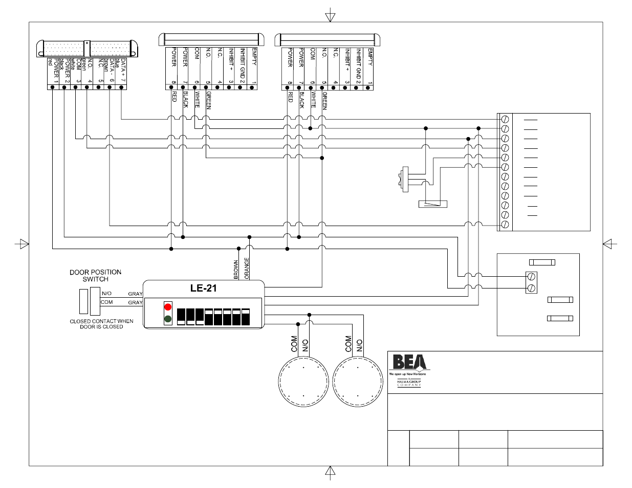
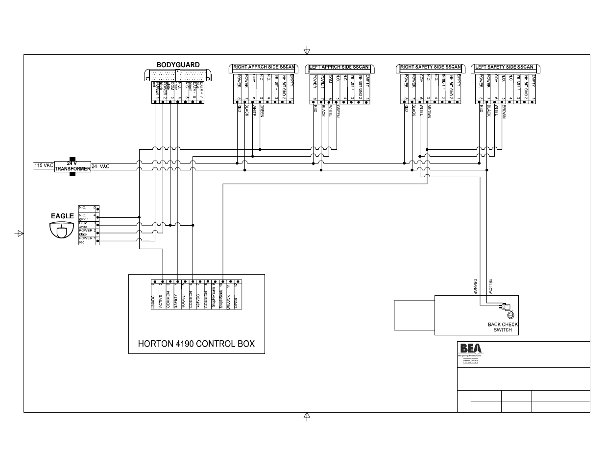 BEA Horton C2150 User Manual Page 2 / 20 From manualsdir.com
- complete, absolutely no missing pages! Above image may vary, depending on model. Breakers and fuses are not supplied. International 3200, 4100, 4300, 4400. Cycle the door and check for proper lock operaton. 4100, 4200, 4300, 4400, 7300, 7400, 7500, 7600, 7700,.
Suffix r2 heater model number indicates honeywell r841d low voltage relay rated 22 amps up to 240.
Check wiring according to diagram. 4100, 4200, 4300, 4400, 7300, 7400, 7500, 7600, 7700,. Pull the switched power wires to the door frame. These 4100 series graphic modules are available internally mounted and ul listed in custom graphic annunciator panels and custom graphic smoke control annunciators from space age electronics inc., website: Here is a picture gallery about horton fan wiring diagram complete with the description of the image, please find the image you need. Connect converter hot to an available breaker.

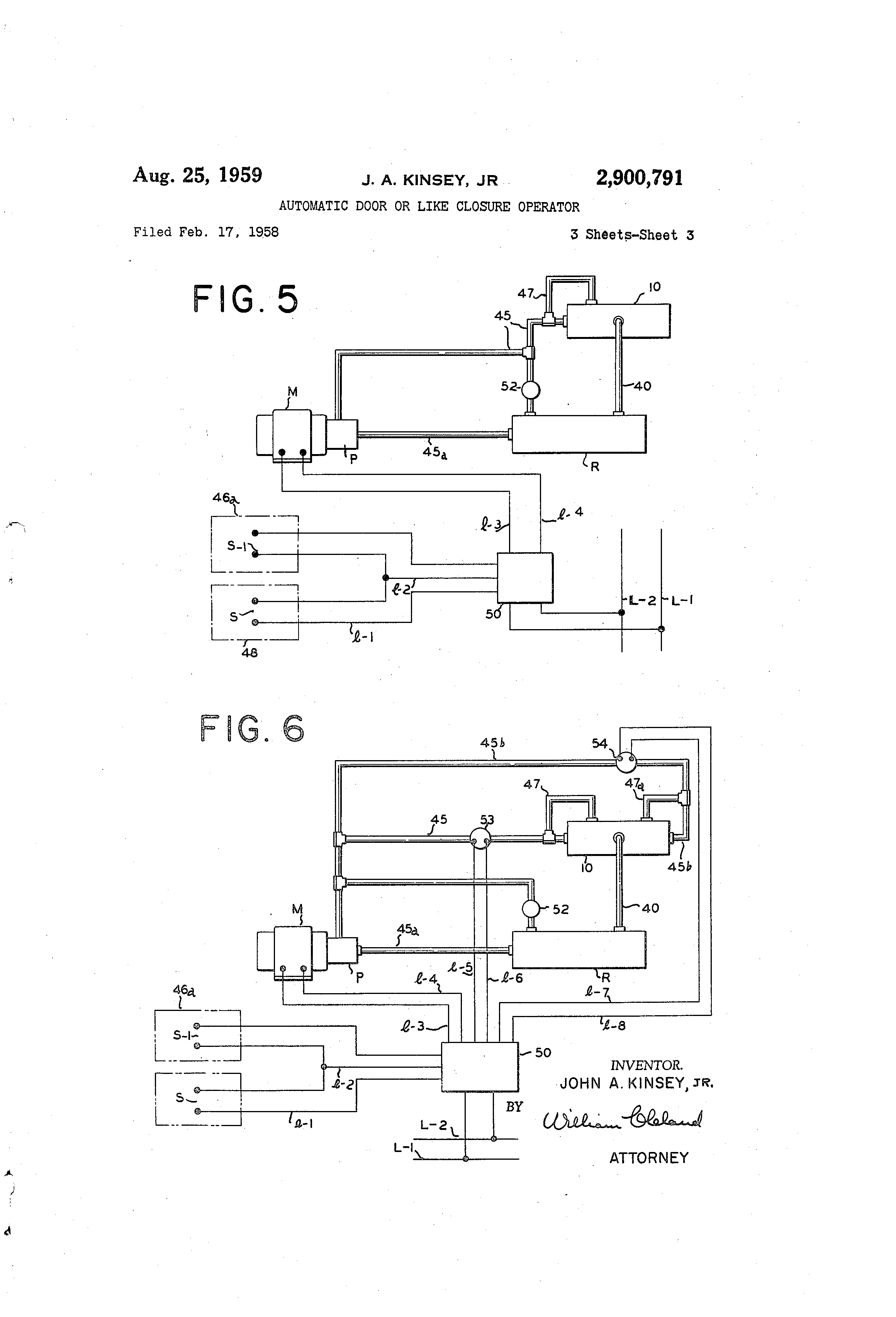
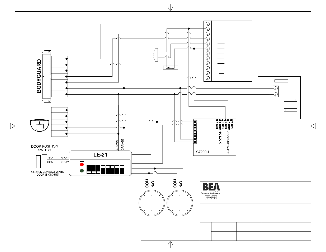
Electrical wiring diagram for a 2000 international 9900i with a 3406 e cat engine answered by a verified technician we use cookies to give you the best possible experience on our website. Horton series 4000 underground conversion. Wiring diagrams case studies master downloads obsolete products. Bea horton 80 0091 02 wiring diagram pdf manualslib c4160 1 2 w lo21 lo21s bg dk12 manualzz manuals c4190 control eagle c3938 p s c2150 user manual page 14 20 original mode motor 19 0240 04 quad systems llc wizard interior exterior sidelite iris 3 this one bodyguard 0000 preview for free stanley dip switch i. Note solenoid valve may or may not have internal diode protection.

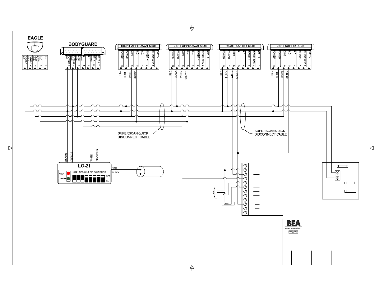
With engine temperature below the thermal switch setting, start engine and build up air pressure install jumper wire between terminals of thermal switch to engage fan drive, or Horton series 4000 underground conversion. 4100 series unit line warning: Horton fan wiring diagram inside horton fan wiring diagram by admin from the thousands of pictures on the web in relation to horton fan wiring diagram, we all selects the best choices using ideal image resolution only for you, and now this photographs is actually considered one of photos series inside our ideal graphics gallery with regards to. Horton 4190, parallax 2,lo21, quick disconnect approach.
 Source: schematron.org
These instructions must be followed to avoid damage to this product. Connect converter hot to an available breaker. Standard arm 4 1/2 (114) series 4000 electric operator output shaft drill all holes #7 (.201) through backmember & frame. Wiring 17 introduction related documentation in this publication. 3200, 4200, 4300, 4400, 7300, 7400, 7500, 7600, 8500, 8600 series built after march 10, 2004 — electrical circuit diagrams i table of contents
 Source: wiringdiagram.2bitboer.com
Here is a picture gallery about horton fan wiring diagram complete with the description of the image, please find the image you need. Our engineers, our distributors, our employees deliver the broadest, deepest, most advanced, most innovative product lines in our industry. 4100 series unit line warning: Wiring 17 introduction related documentation in this publication. Horton kysor leece neville lucas.
 Source: schematron.org
Connect the c3881 to cn2 as shown. Cycle the door and check for proper lock operaton. Drill f (.257) clearance holes through backmember only. International 4100 international 4200 international 4300 international 4400 international 4700. Eagle c4190 control c3938 p s bea horton c2150 user manual page 14 20.
 Source: wiring121.blogspot.com
Console g special tools order special tools from your toro distributor. Use the bottom wire leads only. Cycle the door and check for proper lock operaton. Before installation of your horton drivemaster fan drive, note the fan drive service install the air pressure switch into the air line between the n.c. 42 (io67) sec sec horton recommended time.
 Source: wiring121.blogspot.com
3200 4100 4200 4300 4400 7300 7400 7500 7600 7700 8500 8600 mxt rxt models built oct. Assembly installation manual opcon in ground conversion kit for horton 4000. Installation and setup of the c control. 3200, 4200, 4300, 4400, 7300, 7400, 7500, 7600, 8500, 8600 series built after march 10, 2004 — electrical circuit diagrams i table of contents Vehicles wired normally open (parallel circuit) will require a normally closed solenoid valve (see diagram b).
 Source: wiring121.blogspot.com
Assembly installation manual opcon in ground conversion kit for horton 4000. +1 412 249 4100 north america english. Make necessary connections according to the wiring diagram on the connection box cover. Certain horton valves must be assembled before installation. International 4100 international 4200 international 4300 international 4400 international 4700.
 Source: wiring121.blogspot.com
Assembly installation manual opcon in ground conversion kit for horton 4000. Wire the lock to a horton c3881 auxiliary relay module as per diagram 11380.6. Cycle the door and check for proper lock operaton. Note solenoid valve may or may not have internal diode protection. Connect the c3881 to cn2 as shown.
 Source: diagramweb.net
4100, 4200, 4300, 4400, 7300, 7400, 7500, 7600, 7700,. International 1000 2000 3000 4000 7000 8000 truck wiring. These diagrams show the wiring for particular modules or cards or detector bases which can be used with the 4100es (as4428.1) or 4100esi (as7240.2) simplex fire alarm systems. Unit is not ignition protected. We are committed to exceed your expectations.
 Source: wiring121.blogspot.com
With engine temperature below the thermal switch setting, start engine and build up air pressure install jumper wire between terminals of thermal switch to engage fan drive, or Installation and setup of the c control. Console g special tools order special tools from your toro distributor. 42 (io67) sec sec horton recommended time. Wiring diagrams case studies master downloads obsolete products.
 Source: itencyclopedia.info
Before installation of your horton drivemaster fan drive, note the fan drive service install the air pressure switch into the air line between the n.c. Horton series 4000 underground conversion. Above image may vary, depending on model. Our engineers, our distributors, our employees deliver the broadest, deepest, most advanced, most innovative product lines in our industry. Eagle c4190 control c3938 p s bea horton c2150 user manual page 14 20.
 Source: wiring121.blogspot.com
- complete, absolutely no missing pages! Installation and setup of the c control. Horton fan wiring diagram inside horton fan wiring diagram by admin from the thousands of pictures on the web in relation to horton fan wiring diagram, we all selects the best choices using ideal image resolution only for you, and now this photographs is actually considered one of photos series inside our ideal graphics gallery with regards to. Console g special tools order special tools from your toro distributor. These instructions must be followed to avoid damage to this product.
 Source: schematron.org
Make necessary connections according to the wiring diagram on the connection box cover. International 3200, 4100, 4300, 4400. Make necessary connections according to the wiring diagram on the connection box cover. Connect the power only as the last step.) Prepare door frame as shown on page 2 (based on frame type).
 Source: tianpinyt.blogspot.com
Our engineers, our distributors, our employees deliver the broadest, deepest, most advanced, most innovative product lines in our industry. Installation and setup of the c control. Note solenoid valve may or may not have internal diode protection. Horton fan wiring diagram inside horton fan wiring diagram by admin from the thousands of pictures on the web in relation to horton fan wiring diagram, we all selects the best choices using ideal image resolution only for you, and now this photographs is actually considered one of photos series inside our ideal graphics gallery with regards to. Standard arm 4 1/2 (114) series 4000 electric operator output shaft drill all holes #7 (.201) through backmember & frame.
 Source: manualsdir.com
Vehicles wired normally closed (series circuit) will require a normally open solenoid valve (see diagram a). This sheet numbering is divided into ranges, reflecting the type of device or Wiring diagrams case studies master downloads obsolete products. Installation and setup of the c control. 3200, 4200, 4300, 4400, 7300, 7400, 7500, 7600, 8500, 8600 series built after march 10, 2004 — electrical circuit diagrams i table of contents

4100 series unit line warning: Console g special tools order special tools from your toro distributor. Electrical wiring diagram for a 2000 international 9900i with a 3406 e cat engine answered by a verified technician we use cookies to give you the best possible experience on our website. Cycle the door and check for proper lock operaton. International 1000 2000 3000 4000 7000 8000 truck wiring diagram pdf 1988 vintagemanuals.
 Source: wiring121.blogspot.com
Vehicles wired normally closed (series circuit) will require a normally open solenoid valve (see diagram a). Auto fan wiring diagram wiring diagrams for a ceiling fan way in horton fan wiring diagram, image size 799 x 499 px, and to view image details please click the image. Pull the switched power wires to the door frame. Clean air supply and replace fan clutch. Console g special tools order special tools from your toro distributor.
This site is an open community for users to do submittion their favorite wallpapers on the internet, all images or pictures in this website are for personal wallpaper use only, it is stricly prohibited to use this wallpaper for commercial purposes, if you are the author and find this image is shared without your permission, please kindly raise a DMCA report to Us.
If you find this site good, please support us by sharing this posts to your own social media accounts like Facebook, Instagram and so on or you can also save this blog page with the title horton 4100 series wiring diagram by using Ctrl + D for devices a laptop with a Windows operating system or Command + D for laptops with an Apple operating system. If you use a smartphone, you can also use the drawer menu of the browser you are using. Whether it’s a Windows, Mac, iOS or Android operating system, you will still be able to bookmark this website.
Category
Related By Category
- Predator 670 engine wiring diagram Idea
- Frsky x8r wiring diagram information
- Pioneer ts wx130da wiring diagram Idea
- Johnson 50 hp wiring diagram Idea
- Kohler voltage regulator wiring diagram Idea
- Johnson 50 hp outboard wiring diagram information
- Kti hydraulic remote wiring diagram Idea
- Pyle plpw12d wiring diagram information
- Tx9600ts wiring diagram information
- Lifan 50cc wiring diagram information