Honeywell st9120u wiring diagram information
Home » Trending » Honeywell st9120u wiring diagram information
Your Honeywell st9120u wiring diagram images are ready in this website. Honeywell st9120u wiring diagram are a topic that is being searched for and liked by netizens today. You can Get the Honeywell st9120u wiring diagram files here. Download all royalty-free photos.
If you’re looking for honeywell st9120u wiring diagram images information connected with to the honeywell st9120u wiring diagram interest, you have visit the right blog. Our site frequently provides you with hints for viewing the highest quality video and image content, please kindly surf and find more informative video articles and images that match your interests.
Honeywell St9120u Wiring Diagram. The st9120c is a class ii. The control also provides user selectable blower delays and through dipswitch settings. 1170063 circuit board wiring diagram for honeywell gas furnace Page 7 2 and review the appliance wiring 24 vac common schematic.
 St9120u Wiring Diagram Complete Wiring Schemas From wiring89.blogspot.com
Powered flow through humidifier, how to install the honeywell st9120u furnace control board, honeywell l4064b2236 combination fan and limit. Stc internal wiring, wiring diagrams. Includes instructions and special wire harnesses for easy replacement. The basic purposes of the st9120u are to monitor the thermostat for heat, cool and fan demands, run the. Led off when control is powered indicates defective control. When installing the st9120u, carefully check all appliance wires to make sure they are all connected to desired terminals at st9120u.
Honeywell universal electronic fan timers installation instructions models:
Going through it step by step without skipping any steps and you should be able to get there. St9120u wiring connections with sv9500/9501 smartvalve system control. It is approx 22 between the housings. Honeywell st9120u 1011 universal electronic fan timer; It�s designed to replace all the honeywell part #s listed below. Honeywell st9120c4057 wiring diagram download.
 Source: arnoldservice.com
The control also provides user selectable blower delays and through dipswitch settings. I need a wire for wire to where every wire go on new style. Wiring caution explosion or fire hazard. Honeywell st9120u wiring diagram / 77 luxury aquastat relay wiring diagram diagram component diagram relay / while it may seem overwhelming, the good news is it isn’t challenging learning how to. Control board thanks for watching how to install the honeywell st9120u furnace control board gas furnace combination, gas furnace control board wiring diagram box diagram 2006 f250 radio wiring diagram parts of a.
 Source: wiring89.blogspot.com
Powered flow through humidifier, how to install the honeywell st9120u furnace control board, honeywell l4064b2236 combination fan and limit. The basic purposes of the st9120u are to monitor the thermostat for heat, cool and fan demands, run the. When i use this same board in the field, all i have to go off of his the manual and the furnace wiring diagram. On the st9101 wiring adapter. Download for free or view this honeywell st9120u manual online on onlinefreeguides.com.
 Source: wiring89.blogspot.com
The st9120c is a class ii. St9120u wiring diagram.incorrect wiring can lead to explosion hazard, fire, turn off power to appliance. Page 7 2 and review the appliance wiring 24 vac common schematic. Wiring point for most of the electrical components in the furnace.the basic purposes of the st9120 are to monitor the thermostat for heat, cool and fan demands, run the. This is a brand new honeywell furnace control circuit board.
 Source: wiring89.blogspot.com
Control board thanks for watching how to install the honeywell st9120u furnace control board gas furnace combination, gas furnace control board wiring diagram box diagram 2006 f250 radio wiring diagram parts of a. Wiring make sure that all wiring complies with local codes and ordinances. The control also provides user selectable blower delays and through dipswitch settings. Instruction sheet supplies full cross reference and wiring guide. When installing the st9120u b carefully check all appliance wires to make sure they are all connected to desired terminals at st9120u b.
 Source: wiring89.blogspot.com
The sv9541 then supplies the 120v to the combustion blower ( connector c3). Looking at the manual wiring diagram and looking at your furnace wiring diagram. Turn on pwer and blower runs at start and nothing else. Includes instructions and special wire harnesses for easy replacement. When i use this same board in the field, all i have to go off of his the manual and the furnace wiring diagram.

Wiring diagram, your home honeywell thermostat wiring lvtravelodge com, honeywell thermostat wiring color code tom s tek stop, honeywell furnace control board manual wordpress com, honeywell gas valve. Take the black wire on the st9101 wiring. St9101 wiring connection in standing pilot system. It is approx 22 between the housings. You will only use one of wiring harnesses in the package (if you require any of them.
 Source: antasyaalinda.blogspot.com
St9101 wiring connection in standing pilot system. Page 7 2 and review the appliance wiring 24 vac common schematic. I used the wiring diagram for st9160 system with sv9510 9520 smartvalve control. The furnace is a 1993 icp There is a relay on the sv9541 that controls it.
 Source: justanswer.com
The control also provides user selectable blower delays and through dipswitch settings. Ok can someone help me with the wiring diagram from a st9120c 4057 to a st9120u. Here is the wiring diagram. The furnace is a 1993 icp Turn on pwer and blower runs at start and nothing else.

Wiring caution explosion or fire hazard. Universal electronic fan timer replaces honeywell st9120, st9101, st9141, and st9160 models installed in gas warm air furnaces. 4 flat plug wiring diagram. I need a wire for wire to where every wire go on new style. Honeywell st9120u wiring diagram / 77 luxury aquastat relay wiring diagram diagram component diagram relay / while it may seem overwhelming, the good news is it isn’t challenging learning how to.
 Source: wiring89.blogspot.com
Stc internal wiring, wiring diagrams. Wiring caution explosion or fire hazard. 5 and 6 for internal. Honeywell st9120u wiring diagram / 77 luxury aquastat relay wiring diagram diagram component diagram relay / while it may seem overwhelming, the good news is it isn’t challenging learning how to. The st9120c is a class ii.
 Source: wiring89.blogspot.com
St9120u wiring connections with sv9500/9501 smartvalve system control. The st9120c is a class ii. Board comes with instructions and several wiring harnessness to convert old plug designs into this updated board. Honeywell cross reference honeywell # cross reference universal gas valve vr8300a3500 robertshaw: It is approx 22 between the housings.
 Source: wiring89.blogspot.com
Some models include an enclosure. It is approx 22 between the housings. The sv9541 then supplies the 120v to the combustion blower ( connector c3). This control is the central wiring point for most of the electrical components in the furnace. Ok can someone help me with the wiring diagram from a st9120c 4057 to a st9120u.
 Source: wiring89.blogspot.com
The sv9541 then supplies the 120v to the combustion blower ( connector c3). Wiring caution explosion or fire hazard. Is the least efficient diagram among the electrical wiring diagram. Here is the wiring diagram. Honeywell st9120u 1011 universal electronic fan timer;

Honeywell st9120u 1011 universal electronic fan timer; Here is the wiring diagram. Wiring diagram in addition on honeywell. Led off when control is powered indicates defective control. 5 and 6 for internal.
 Source: ebay.com
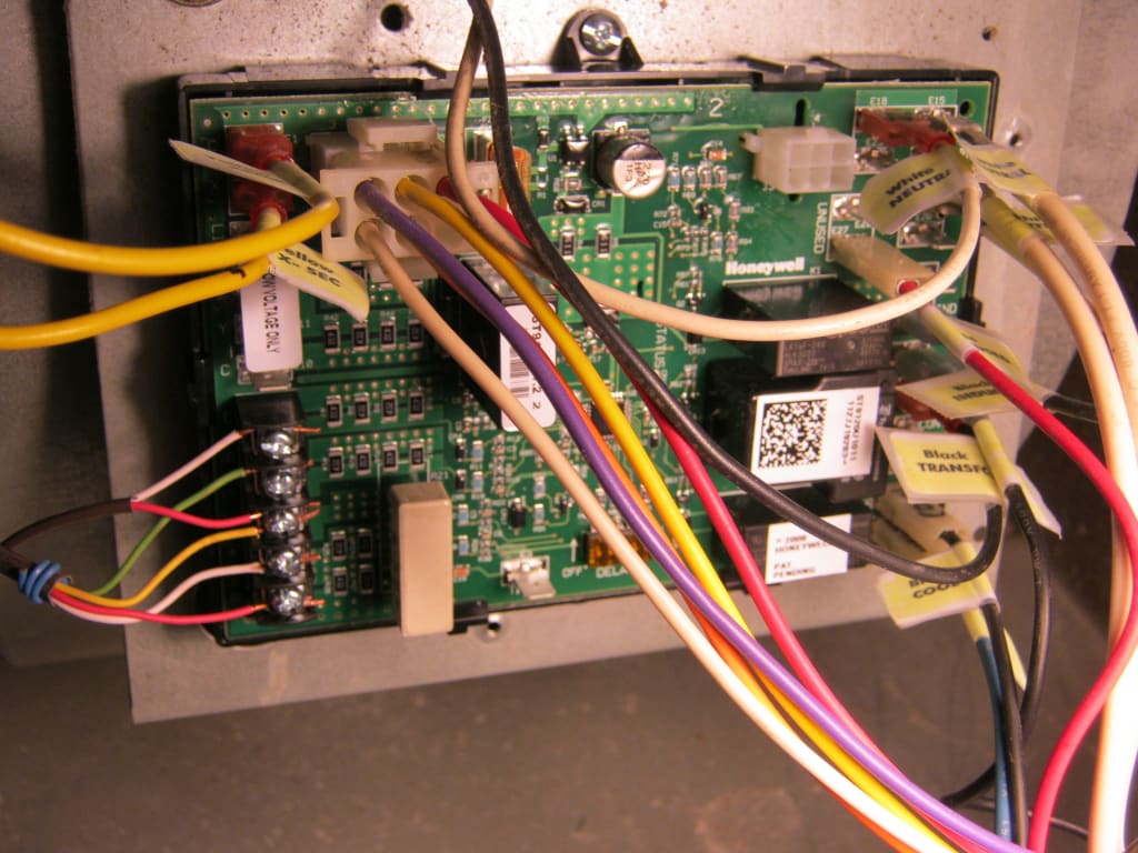
The wiring diagram provided by honeywell does not address on which terminals the orange wires labeled 22 and 21, these leads went to the motor lead terminals on the original controller. Wiring diagram, your home honeywell thermostat wiring lvtravelodge com, honeywell thermostat wiring color code tom s tek stop, honeywell furnace control board manual wordpress com, honeywell gas valve. Interface harnesses for simple conversion. On the st9101 wiring adapter. St9120u1011 honeywell st9120u 1011 electronic fan timer keith specialty honeywell st9120u1011 electronic fan timer ac pro.
 Source: wiring89.blogspot.com
St9101 wiring connection in standing pilot system. When i use this same board in the field, all i have to go off of his the manual and the furnace wiring diagram. Honeywell st9120u 1011 universal electronic fan timer; 5 and 6 for internal. The wiring diagram provided by honeywell does not address on which terminals the orange wires labeled 22 and 21, these leads went to the motor lead terminals on the original controller.
 Source: wiring89.blogspot.com
Ok can someone help me with the wiring diagram from a st9120c 4057 to a st9120u. Turn off power to appliance. Interface harnesses for simple conversion. On the st9101 wiring adapter. I need a wire for wire to where every wire go on new style.
 Source: wiring89.blogspot.com
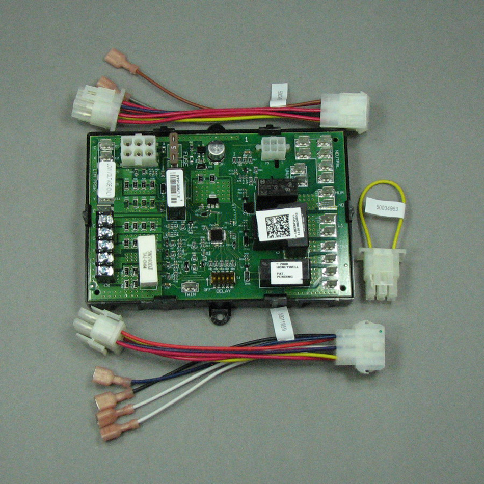
Turn off power to appliance. Universal electronic fan timer replaces honeywell st9120, st9101, st9141, and st9160 models installed in gas warm air furnaces. St9120 to st9120u wiring conversion instructions 1. If not, the structure will not work as it ought to be. Honeywell has replaced all their st9120 series control boards with this universal control board kit, which has wiring harnesess to be used with the furnace you are working on.
This site is an open community for users to do submittion their favorite wallpapers on the internet, all images or pictures in this website are for personal wallpaper use only, it is stricly prohibited to use this wallpaper for commercial purposes, if you are the author and find this image is shared without your permission, please kindly raise a DMCA report to Us.
If you find this site good, please support us by sharing this posts to your favorite social media accounts like Facebook, Instagram and so on or you can also save this blog page with the title honeywell st9120u wiring diagram by using Ctrl + D for devices a laptop with a Windows operating system or Command + D for laptops with an Apple operating system. If you use a smartphone, you can also use the drawer menu of the browser you are using. Whether it’s a Windows, Mac, iOS or Android operating system, you will still be able to bookmark this website.
Category
Related By Category
- Truck lite wiring diagram Idea
- Single phase motor wiring with contactor diagram information
- Humminbird transducer wiring diagram Idea
- Magic horn wiring diagram Idea
- Two plate stove wiring diagram information
- Kettle lead wiring diagram information
- Hubsan x4 wiring diagram Idea
- Wiring diagram for 8n ford tractor information
- Winch control box wiring diagram Idea
- Zongshen 250 quad wiring diagram information