Honeywell pro 3200 wiring diagram information
Home » Trend » Honeywell pro 3200 wiring diagram information
Your Honeywell pro 3200 wiring diagram images are ready in this website. Honeywell pro 3200 wiring diagram are a topic that is being searched for and liked by netizens now. You can Get the Honeywell pro 3200 wiring diagram files here. Download all royalty-free vectors.
If you’re searching for honeywell pro 3200 wiring diagram images information related to the honeywell pro 3200 wiring diagram topic, you have pay a visit to the ideal site. Our site always provides you with suggestions for downloading the highest quality video and picture content, please kindly surf and find more enlightening video content and graphics that match your interests.
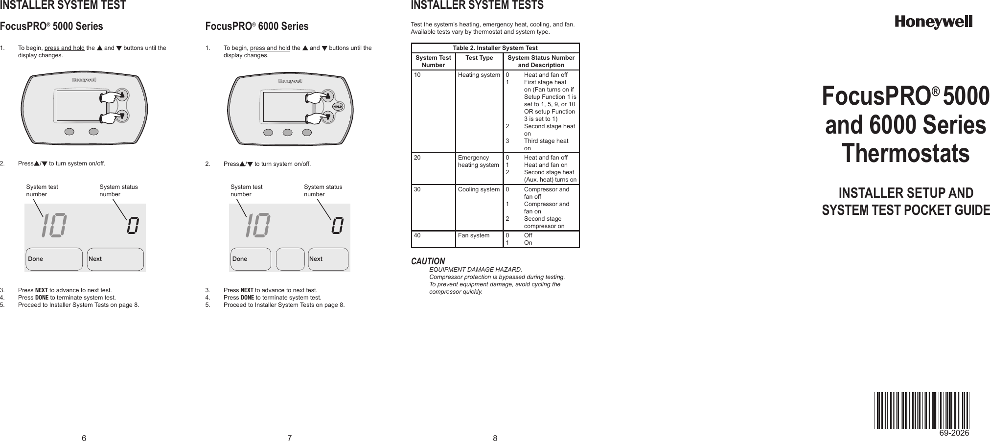
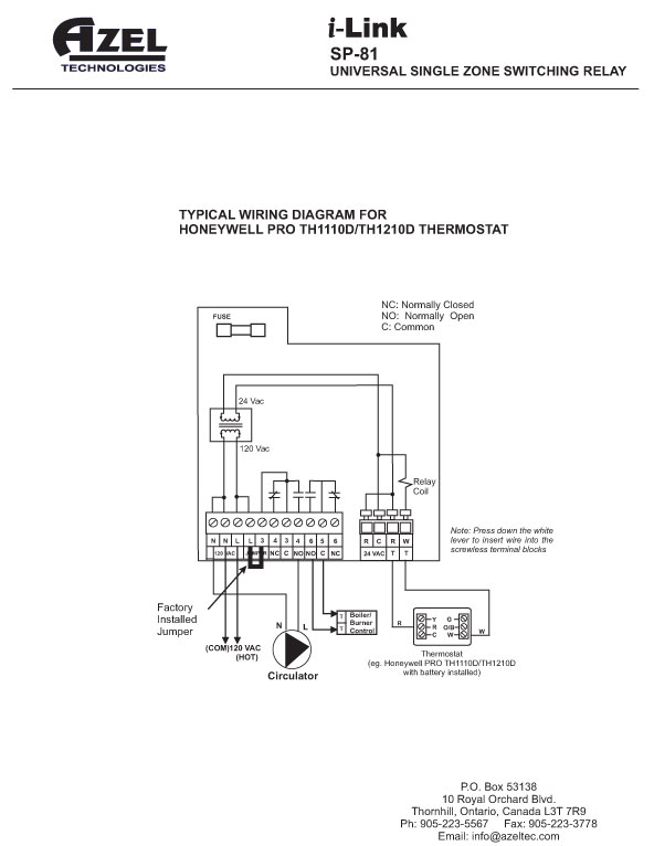
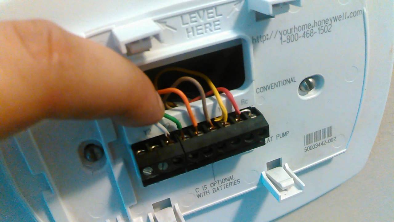
Honeywell Pro 3200 Wiring Diagram. Part of the honeywell home t series of thermostats from resideo, the t4 pro programmable thermostat helps you manage your home heating and cooling in a simple, easy to use device. [3]optional 24 vac common connection. Power method display information limited warranty wiring terminals thd 1heat/1cool backlit thd 2heat/1cool (heatpump) backlit. Optional 24 vac common connection.
Diagram For Wiring A Honeywell 3000 Wiring Diagram From cars-trucks24.blogspot.com
Wiring diagram for honeywell vision pro 8000. C honeywell v8043 zone valves 1 th tr. Shielded cable is not required. A turn on 24vac now. 39 honeywell thermostat wiring diagram 6 wire. If you have a c wire, place it into the c terminal on your wall plate.
Help wiring a new honeywell 8000 for dehum doityourself.
Use a piece of wire (not supplied) to connect w and y terminals to each other. Here we have 8 models on honeywell pro series wiring diagram including images, pictures, models, photos, etc. [3]optional 24 vac common connection. Gas or oil furnace cool only c g w r s s y y2 g c u u a w2 w k rc r l/a e aux m36882 1 common optional. Most heat only, gas or oil forced air systems do not use a fan (g) wire. Honeywell never recommends using the pro3200 or related products for use as a primary warning or monitoring system.
 Source: schematron.org
If there are wires in terminals that are not listed you will need additional wiring support. Shielded cable is not required. Here we have 8 models on honeywell pro series wiring diagram including images, pictures, models, photos, etc. For the y, y1, and y2 wires, y or y1 will go to the y terminal, and y2 will go to the y2 terminal. Honeywell visionpro 8000 wiring diagram.
 Source: ricardolevinsmorales.com
The next t stat the honeywell t8775c1005 2 non programmable t stat can control both heating and cooling as. Here we have 8 models on honeywell pro series wiring diagram including images, pictures, models, photos, etc. If not, the arrangement won’t function as it. Wiring diagram for honeywell vision pro 8000. Help wiring a new honeywell 8000 for dehum doityourself.
Source: shortbobhairstylesforfinehair.blogspot.com
Heating controls wiring guide issue 17. Wiring diagram for connectors 6 through 10 Page 135 visionpro 8000 with redlink zoning the following diagrams show the wiring for zoning with different iaq equipment. Honeywell programmable pro th thermostate to connect to a rheem rqnj series heat. Here we have 8 models on honeywell pro series wiring diagram including images, pictures, models, photos, etc.
 Source: wiringforums.com
Wiring diagram for connectors 1 through 8. Wiring diagram for connectors 1 through 8. Th4110u2005/u th4210u2002/u wiring diagrams [pdf]: Honeywell wiring diagram for thermostat. 1 pull wires through wire hole.
Source: schematicandwiringdiagram.blogspot.com
If there are wires in terminals that are not listed you will need additional wiring support. Refer to the table and wiring diagrams on the next page. Let�s take a look at the g wire. Honeywell t4m quick start installation manual pdf manualslib. Wiring conventional and heat pump systems notes wire specifications:
 Source: jenniandmattwhitmarsh.blogspot.com
14 wiring diagram for connectors 7 through 10. Honeywell never recommends using the pro3200 or related products for use as a primary warning or monitoring system. Home > professional zone > resource centre > wiring diagrams. Here we have 8 models on honeywell pro series wiring diagram including images, pictures, models, photos, etc. Wiring diagram for connectors 6 through 10
 Source: ricardolevinsmorales.com
Help wiring a new honeywell 8000 for dehum doityourself. Honeywell wiring diagram for thermostat. Efs your new honeywell thermostat has been designed to give you many years of. T4 and t1 pro wiring diagrams specifications t4 pro programmable thermostat color white… honeywell pro 2000 series programmable thermostat user guide If this connection is not made, use batteries to power the thermostat.
 Source: schematron.org
Honeywell programmable thermostat t4 pro installation guide manuals. You can either mount the board in a rack or open and flat. 14 wiring diagram for connectors 7 through 10. Set the o/b jumper according to the type of reversing valve (see page 4). C honeywell v8043 zone valves 1 th tr.
 Source: ricardolevinsmorales.com
This wire will go to the g terminal on your new thermostat. T6 pro wiring diagrams wiring diagrams heat only: On this website, we also have variety of pics usable. Heat pump thermostat wiring chart diagram quality 101. For the y, y1, and y2 wires, y or y1 will go to the y terminal, and y2 will go to the y2 terminal.
 Source: muienertan2.blogspot.com
Honeywell digital thermostat wiring diagram wiring solutions. Here we have 8 models on honeywell pro series wiring diagram including images, pictures, models, photos, etc. Primary warning or monitoring systems Honeywell programmable pro th thermostate to connect to a rheem rqnj series heat. 1 pull wires through wire hole.
 Source: diagramweb.net
14 wiring diagram for connectors 7 through 10. These wiring diagrams are for guidance only and at the time of publication represent the latest information. [3]optional 24 vac common connection. 1 pull wires through wire hole. 24vac (c wire) is required.
 Source: kiiroiboru7.blogspot.com
Provide disconnect means and overload protection as required. Wiring diagram for connectors 1 through 8. Wiring diagram to connect programmable thermo to heat pump. Gas or oil furnace cool only c g w r s s y y2 g c u u a w2 w k rc r l/a e aux m36882 1 common optional. Honeywell pro series wiring diagram you need to know is served for all of you in this post.
Source: diymicarta.blogspot.com
We will cover the most common thermostat wirings for 2 wire 3 wire 4 wire and 5 wire thermostats. Heat pump thermostat wiring chart diagram quality 101. Let�s take a look at the g wire. Optional 24 vac common connection. The visionpro® with redlink™ system can be wired directly to the equipment.
 Source: diagramweb.net
Honeywell pro th4000 wiring diagram. Honeywell digital thermostat wiring diagram wiring solutions. Such as png, jpg, animated gifs, pic art, logo, black and white, transparent, etc about. Honeywell programmable thermostat t4 pro installation guide manuals. Refer to the table and wiring diagrams on the next page.
Source: cars-trucks24.blogspot.com
Wiring diagram for connectors 1 through 7 Primary warning or monitoring systems Most heat only, gas or oil forced air systems do not use a fan (g) wire. If you have a c wire, place it into the c terminal on your wall plate. G used for independent fan control only.
 Source: diagramweb.net
Honeywell visionpro 8000 wiring diagram. Wiring diagram to connect programmable thermo to heat pump. Honeywell programmable thermostat t4 pro installation guide manuals. Honeywell t4m quick start installation manual pdf manualslib. Wiring diagram for honeywell vision pro 8000.
Source: cars-trucks24.blogspot.com
You can either mount the board in a rack or open and flat. Use a piece of wire (not supplied) to connect w and y terminals to each other. Honeywell t4m quick start installation manual pdf manualslib. Honeywell visionpro 8000 wiring diagram. 24vac (c wire) is required.
 Source: schematron.org
Mounting plate with four wires of the honeywell large dial thermostat model t87n1026. The honeywell home trademark is used under license from honeywell international inc. Efs your new honeywell thermostat has been designed to give you many years of. Wiring diagram for connectors 1 through 8. It controls up to 3 heat/2 cool heat pump systems or up to 2 heat/2 cool conventional systems.
This site is an open community for users to submit their favorite wallpapers on the internet, all images or pictures in this website are for personal wallpaper use only, it is stricly prohibited to use this wallpaper for commercial purposes, if you are the author and find this image is shared without your permission, please kindly raise a DMCA report to Us.
If you find this site helpful, please support us by sharing this posts to your own social media accounts like Facebook, Instagram and so on or you can also save this blog page with the title honeywell pro 3200 wiring diagram by using Ctrl + D for devices a laptop with a Windows operating system or Command + D for laptops with an Apple operating system. If you use a smartphone, you can also use the drawer menu of the browser you are using. Whether it’s a Windows, Mac, iOS or Android operating system, you will still be able to bookmark this website.
Category
Related By Category
- Predator 670 engine wiring diagram Idea
- Frsky x8r wiring diagram information
- Pioneer ts wx130da wiring diagram Idea
- Johnson 50 hp wiring diagram Idea
- Kohler voltage regulator wiring diagram Idea
- Johnson 50 hp outboard wiring diagram information
- Kti hydraulic remote wiring diagram Idea
- Pyle plpw12d wiring diagram information
- Tx9600ts wiring diagram information
- Lifan 50cc wiring diagram information