Honeywell control module wiring diagram information
Home » Trending » Honeywell control module wiring diagram information
Your Honeywell control module wiring diagram images are available in this site. Honeywell control module wiring diagram are a topic that is being searched for and liked by netizens today. You can Get the Honeywell control module wiring diagram files here. Download all royalty-free images.
If you’re searching for honeywell control module wiring diagram pictures information linked to the honeywell control module wiring diagram keyword, you have visit the ideal blog. Our site frequently provides you with suggestions for seeing the highest quality video and picture content, please kindly search and locate more enlightening video articles and images that fit your interests.
Honeywell Control Module Wiring Diagram. Pilot gas provides labels to help assure proper marking of the wires. The su universal replacement ignition module is. Use the power from the jade to power the co2 sensor or make sure the ground for the power supplies are common. Your local honeywell automation and control products sales office (check white pages of your phone directory).
 Honeywell Ignition Module Wiring Diagram Wiring Diagram From wiringschemas.blogspot.com
Index of /manuals/ademco/control panels/vista vistabp wiringall.com · vistabp v1 installation wiringall.com · vistabp v1 program wiringall.com vistafbp fbp owners manual, pdf, kb, 01/25/, owners manual. Install module wiring in accordance with the job drawings and appropriate wiring diagrams. Wiring diagram for limit control module. Check the wiring diagram furnished by the. Click the icon or the document title to download the. Refer to wiring diagram of.
Remove old control from subbase.
Your local honeywell automation and control products sales office (check white pages of your phone directory). For the y y1 and y2 wires y or y1 will go to the y terminal and y2 will go to the y2 terminal. See wiring diagram below for the c7232 and c7632 wiring. Honeywell s8610u3009 universal intermittent pilot ignition module for honeywell s8610u wiring diagram by admin from the thousands of photos on the internet about honeywell s8610u wiring diagram, we all choices the very best series together with best resolution just for you all, and this pictures is one of pictures libraries inside our greatest graphics gallery. The barrier must be inserted into a 4″x4″x21 / 8 Your local honeywell automation and control products sales office (check white pages of your phone directory).
 Source: wiringall.com
Pilot gas provides labels to help assure proper marking of the wires. Check the wiring diagram furnished by the. Install module wiring in accordance with the job drawings and appropriate wiring diagrams. The thermostat uses 1 wire to control each of your hvac systems primary functions such as heating cooling fan etc. Installing the va panel link module, figure panel linking block diagram, figure va panel link.
 Source: wiringall.com
For the y y1 and y2 wires y or y1 will go to the y terminal and y2 will go to the y2 terminal. Honeywell su universal intermittent pilot control module (one or two rods) has continuous retry trial time, configurable lockout timing of 15 or 90 seconds and configurable prepurge of price: Again referring to the honeywell thermostat ct31a wiring diagram, you can see it requires only two wires, r and w. Turn on power and gas supply. Based integrated burner control for automatically.
 Source: wiringall.com
Installing the va panel link module, figure panel linking block diagram, figure va panel link. S89e typical hookup in di rect spark control system. Your local honeywell automation and control products sales office (check white pages of your phone directory). Set thermostat to call for heat. 8 for control system ladder diagram.
 Source: rajuyolo10.blogspot.com
3 use a screwdriver to loosen terminal screw. The honeywell rm/rm relay modules are qa,b terminal wiring subbase product. Provide disconnect means and overload protection as required. Refer to table 2 for a list of the wiring diagrams and 4 through 10 for typical wiring diagrams:
 Source: schematron.org
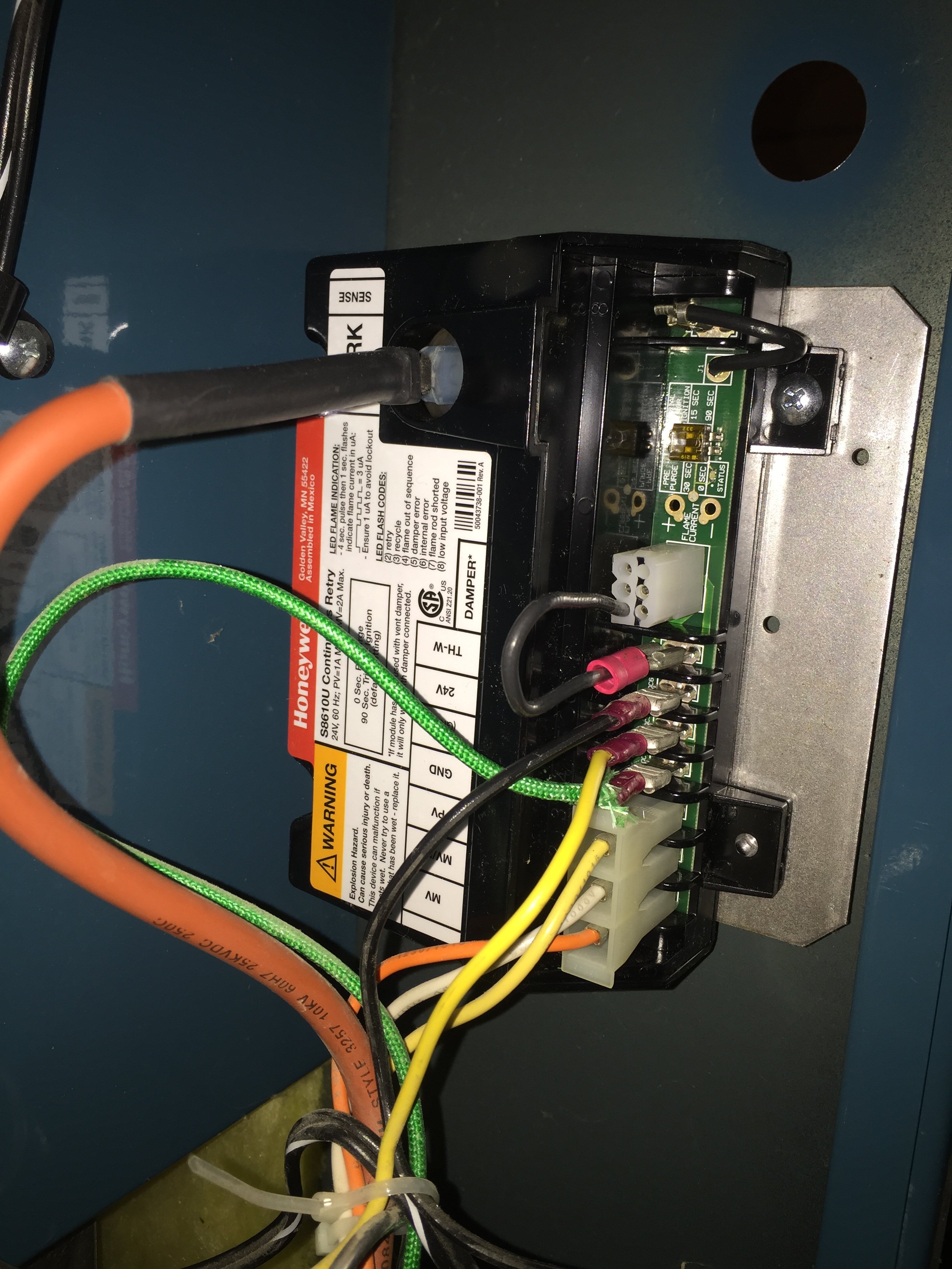
If the vent damper is connected, wire 24v terminal, as shown. See wiring diagram below for the c7232 and c7632 wiring. Contains all the essential wiring diagrams across our range of heating controls. Turn on power and gas supply. View and download honeywell su installation instructions manual online.
 Source: wiringschemas.blogspot.com
The honeywell home trademark is used under license from honeywell. The honeywell tc810r1024 addressable relay module provides the system with a dry contact output for activating a variety of auxiliary devices, such as fans, dampers, control equipment, etc. 1—mounting dimensions of rm relay module and. Our wiring diagrams section details a selection of key wiring diagrams focused around typical sundial s and y plans. The honeywell home trademark is used under license from honeywell.
 Source: forum.heatinghelp.com
Based integrated burner control for automatically. Honeywell su universal intermittent pilot control module (one or two rods) has continuous retry trial time, configurable lockout timing of 15 or 90 seconds and configurable prepurge of price: Remove old control from subbase. 1—mounting dimensions of rm relay module and. And meets their if cad cell leads are run with line voltage wires, breakout knockout at the.
 Source: schematron.org
Honeywell home st699 electronic dual zone timer installation guide manuals swapping a hw for st9400 diynot forums to hive instructions pdf manualslib datasheet datasheet4u com st799 classic programmer data sheet page 2 and nest heating controls 23 avforums tony webber. X4 x21/8 junction box, and the control module must be placed into the barrier and attached to the junction box (figure 2a). Use the power from the jade to power the co2 sensor or make sure the ground for the power supplies are common. Make wiring connections and mount control. Co2 sensor wiring when using the c7232 honeywell co2 sensors the black and brown common wires are internally connected and only one is connected to “iaq com” on the jade.
 Source: schematron.org
Economizer logic modules for ventilation control application w7212, w7213, and w7214 economizer logic modules are. Your local honeywell automation and control products sales office (check white pages of your phone directory). And meets their if cad cell leads are run with line voltage wires, breakout knockout at the. Refer to wiring diagram of. 4 through 10 for typical wiring diagrams:
 Source: schematron.org
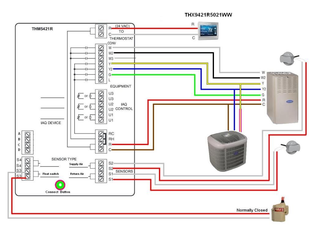
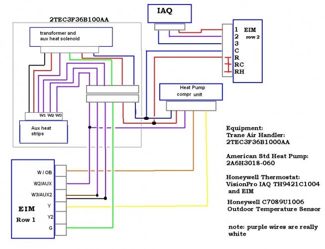
Use the power from the jade to power the co2 sensor or make sure the ground for the power supplies are common. Honeywell home st699 electronic dual zone timer installation guide manuals swapping a hw for st9400 diynot forums to hive instructions pdf manualslib datasheet datasheet4u com st799 classic programmer data sheet page 2 and nest heating controls 23 avforums tony webber. A few months ago i installed 2 stats honeywell thx9421 2 wires through eim so zone 1 could also control a aprilair humidifier and i could control tstats through my smartphone. Look at the thermostat wiring checklist from step 8 or the photo you took. Location of c7400 outdoor and re turn air sensors, c7150 mixed air sensor , and c7046.
 Source: schematron.org
Remove old control from subbase. Honeywell s8610u3009 universal intermittent pilot ignition module for honeywell s8610u wiring diagram by admin from the thousands of photos on the internet about honeywell s8610u wiring diagram, we all choices the very best series together with best resolution just for you all, and this pictures is one of pictures libraries inside our greatest graphics gallery. Again referring to the honeywell thermostat ct31a wiring diagram, you can see it requires only two wires, r and w. The thermostat uses 1 wire to control each of your hvac systems primary functions such as heating cooling fan etc. By iot | september 14, 2021.
 Source: schematron.org
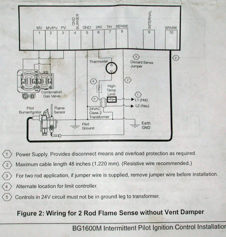
If the vent damper is connected, wire 24v terminal, as shown. Make wiring connections and mount control. Addressability allows dry contact activated, either manually or through panel programming, on a select bas through panel programming, on a select basis. Here is a picture gallery about honeywell s8610u wiring diagram complete with the description of the image, please find the image you need. Honeywell s8610u3009 universal intermittent pilot ignition module for honeywell s8610u wiring diagram by admin from the thousands of photos on the internet about honeywell s8610u wiring diagram, we all choices the very best series together with best resolution just for you all, and this pictures is one of pictures libraries inside our greatest graphics gallery.
 Source: askmehelpdesk.com
Honeywell s8610u3009 universal intermittent pilot ignition module for honeywell s8610u wiring diagram by admin from the thousands of photos on the internet about honeywell s8610u wiring diagram, we all choices the very best series together with best resolution just for you all, and this pictures is one of pictures libraries inside our greatest graphics gallery. Refer to table 2 for a list of the wiring diagrams and Turn on power and gas supply. X4 x21/8 junction box, and the control module must be placed into the barrier and attached to the junction box (figure 2a). Contains all the essential wiring diagrams across our range of heating controls.
 Source: wiringschemas.blogspot.com
For the y y1 and y2 wires y or y1 will go to the y terminal and y2 will go to the y2 terminal. By iot | september 14, 2021. It doesn�t control cooling and, because it�s a mechanical thermostat, it doesn�t need power for internal. A few months ago i installed 2 stats honeywell thx9421 2 wires through eim so zone 1 could also control a aprilair humidifier and i could control tstats through my smartphone. Economizer logic modules for ventilation control application w7212, w7213, and w7214 economizer logic modules are.
 Source: diagramweb.net
Here is a picture gallery about honeywell s8610u wiring diagram complete with the description of the image, please find the image you need. The barrier must be inserted into a 4″x4″x21 / 8 Provide disconnect means and overload protection as required. Pilot gas provides labels to help assure proper marking of the wires. Make wiring connections and mount control.
 Source: jumpstarterdiscount.blogspot.com
Location of c7400 outdoor and re turn air sensors, c7150 mixed air sensor , and c7046. If you like this picture please right click and save the picture, thanks for visiting this website, we provide a lot of options related to honeywell su wiring diagram images. Location of c7400 outdoor and re turn air sensors, c7150 mixed air sensor , and c7046. It doesn�t control cooling and, because it�s a mechanical thermostat, it doesn�t need power for internal. View and download honeywell su installation instructions manual online.
 Source: rajuyolo10.blogspot.com
Red wire rh 24v power should have an exsisting jumper to rc changing from a 6 wire manual round. The su replaces existing flame rectification type. See wiring diagram below for the c7232 and c7632 wiring. Honeywell home st699 electronic dual zone timer installation guide manuals swapping a hw for st9400 diynot forums to hive instructions pdf manualslib datasheet datasheet4u com st799 classic programmer data sheet page 2 and nest heating controls 23 avforums tony webber. 8 for control system ladder diagram.
 Source: diagramweb.net
Refer to table 2 for a list of the wiring diagrams and The honeywell tc810r1024 addressable relay module provides the system with a dry contact output for activating a variety of auxiliary devices, such as fans, dampers, control equipment, etc. Red wire rh 24v power should have an exsisting jumper to rc changing from a 6 wire manual round. 4 through 10 for typical wiring diagrams: 3 use a screwdriver to loosen terminal screw.
This site is an open community for users to do sharing their favorite wallpapers on the internet, all images or pictures in this website are for personal wallpaper use only, it is stricly prohibited to use this wallpaper for commercial purposes, if you are the author and find this image is shared without your permission, please kindly raise a DMCA report to Us.
If you find this site good, please support us by sharing this posts to your own social media accounts like Facebook, Instagram and so on or you can also save this blog page with the title honeywell control module wiring diagram by using Ctrl + D for devices a laptop with a Windows operating system or Command + D for laptops with an Apple operating system. If you use a smartphone, you can also use the drawer menu of the browser you are using. Whether it’s a Windows, Mac, iOS or Android operating system, you will still be able to bookmark this website.
Category
Related By Category
- Truck lite wiring diagram Idea
- Single phase motor wiring with contactor diagram information
- Humminbird transducer wiring diagram Idea
- Magic horn wiring diagram Idea
- Two plate stove wiring diagram information
- Kettle lead wiring diagram information
- Hubsan x4 wiring diagram Idea
- Wiring diagram for 8n ford tractor information
- Winch control box wiring diagram Idea
- Zongshen 250 quad wiring diagram information