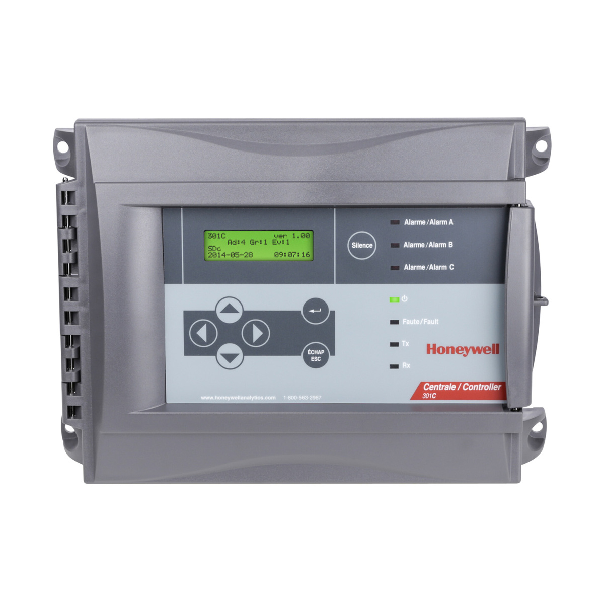
Honeywell 301c wiring diagram information
Home » Trending » Honeywell 301c wiring diagram information
Your Honeywell 301c wiring diagram images are ready in this website. Honeywell 301c wiring diagram are a topic that is being searched for and liked by netizens now. You can Get the Honeywell 301c wiring diagram files here. Get all free vectors.
If you’re searching for honeywell 301c wiring diagram images information related to the honeywell 301c wiring diagram keyword, you have pay a visit to the ideal site. Our site always provides you with suggestions for seeing the highest quality video and picture content, please kindly hunt and find more enlightening video content and images that match your interests.
Honeywell 301c Wiring Diagram. 301c controller with multiple e3point gas detectors. (r provides a resistance termination and rc Ensure to orient the air holes on the air intake tube to face the airflow. 201c 301c dip1 dip2 dip3 dip4 1 or 17 81 off off off off 2 or 18 82 on off off off.
 301C Gas Detection Network Controller Valley From vtlsales.ca
Terminal blocks, input, and communication: Wiring diagram xv95 2 stage ac aprilaire 600 to honeywell iaq doityourself com community forums. Wiring diagram can be found in the related tab. The most common connections are shown in. Optional horn and strobe will quickly alert personnel when gas is detected. The diagram below provides the details required to connect the 301c controller with power, transmitters, external relay loads, and bacnet.
Wiring diagram xv95 2 stage ac aprilaire 600 to honeywell iaq doityourself com community forums.
The honeywell 301c controller monitors and controls toxic and combustible gases and oxygen hazards. Wiring diagram xv95 2 stage ac aprilaire 600 to honeywell iaq doityourself com community forums. Delivers sophisticated control functionality for up to twenty remote refrigerant sensors and detects a wide variety of gases. Per 301c / aa96d maximum 16 modules : Honeywell home th1110d2009 th1010d2000 y plan central heating system s thermostat wiring diagrams quality hvac faq pump overrun for t6 diynot how does an work th8320wf user manual schneider electric solar plus diagram wireless programmable to wire t3 installation connections room thermostats st9400a. Wiring details the diagram below provides the details required to connect the 301c controller with power, transmitters, external relay loads, and bacnet.

Honeywell disclaims all warranties and liability in connection with the drawing. Wiring diagram for honeywell r132a switching relay doityourself com community forums. Honeywell disclaims all warranties and liability in connection with the drawing. The answer / solution to the problem / question documented in this article. Honeywell disclaims all warranties and liability in connection with the drawing.
 Source: guguorlando777.weebly.com
Details concerning power supply, cables, capacities, etc., are provided in the specifications section at the back of. Per 301c / aa96d maximum 16 modules : If one or more of the connected devices is in an alarm mode, the controller will only scroll between the main information screen and the screens for device (s) in alarm mode. Honeywell home th1110d2009 th1010d2000 y plan central heating system s thermostat wiring diagrams quality hvac faq pump overrun for t6 diynot how does an work th8320wf user manual schneider electric solar plus diagram wireless programmable to wire t3 installation connections room thermostats st9400a. Designed for simple installation and operation, the 301c continuously monitors and controls toxic gases, combustible gases and oxygen hazards.
 Source: vtlsales.ca
Wiring diagram for honeywell r132a switching relay doityourself com community forums. Honeywell disclaims all warranties and liability in connection with the drawing. Designed for installation and operational efficiency, the 301c reduces the cost of installation and decreases the overall cost of ownership. 301c controller with multiple e3point gas detectors. Connect wires according to the wiring details.
 Source: dhrocketry.com
Designed for installation and operational efficiency, the 301c reduces the cost of installation and decreases the overall cost of ownership. Honeywell disclaims all warranties and liability in connection with the drawing. Honeywell fan centers r8239a h at72h j q633a user guide manuals. Modbus communication channels are included. Wiring details the diagram below provides the details required to connect the 301c controller with power, transmitters, external relay loads, and bacnet.
This site is an open community for users to do submittion their favorite wallpapers on the internet, all images or pictures in this website are for personal wallpaper use only, it is stricly prohibited to use this wallpaper for commercial purposes, if you are the author and find this image is shared without your permission, please kindly raise a DMCA report to Us.
If you find this site adventageous, please support us by sharing this posts to your preference social media accounts like Facebook, Instagram and so on or you can also bookmark this blog page with the title honeywell 301c wiring diagram by using Ctrl + D for devices a laptop with a Windows operating system or Command + D for laptops with an Apple operating system. If you use a smartphone, you can also use the drawer menu of the browser you are using. Whether it’s a Windows, Mac, iOS or Android operating system, you will still be able to bookmark this website.
Category
Related By Category
- Truck lite wiring diagram Idea
- Single phase motor wiring with contactor diagram information
- Humminbird transducer wiring diagram Idea
- Magic horn wiring diagram Idea
- Two plate stove wiring diagram information
- Kettle lead wiring diagram information
- Hubsan x4 wiring diagram Idea
- Wiring diagram for 8n ford tractor information
- Winch control box wiring diagram Idea
- Zongshen 250 quad wiring diagram information