Hid v1000 wiring diagram Idea
Home » Trending » Hid v1000 wiring diagram Idea
Your Hid v1000 wiring diagram images are available. Hid v1000 wiring diagram are a topic that is being searched for and liked by netizens today. You can Get the Hid v1000 wiring diagram files here. Download all free images.
If you’re searching for hid v1000 wiring diagram pictures information connected with to the hid v1000 wiring diagram keyword, you have come to the right site. Our site frequently gives you hints for viewing the highest quality video and picture content, please kindly hunt and locate more enlightening video content and images that fit your interests.
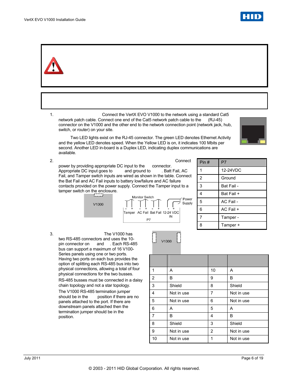
Hid V1000 Wiring Diagram. 1.2 v1000 or v2000 1. 1 v1000 used with v1000 (access controller) any combination of (up to 32) interface note: For example, two panels, both with interface address 0 (factory default), cannot be connected to ports 1 and/or 2 (p1). The v physical rs port 1 and 2 reside on logical bus 1 (p3), while port 3 and 4 reside on rs logical bus 2 (p4).
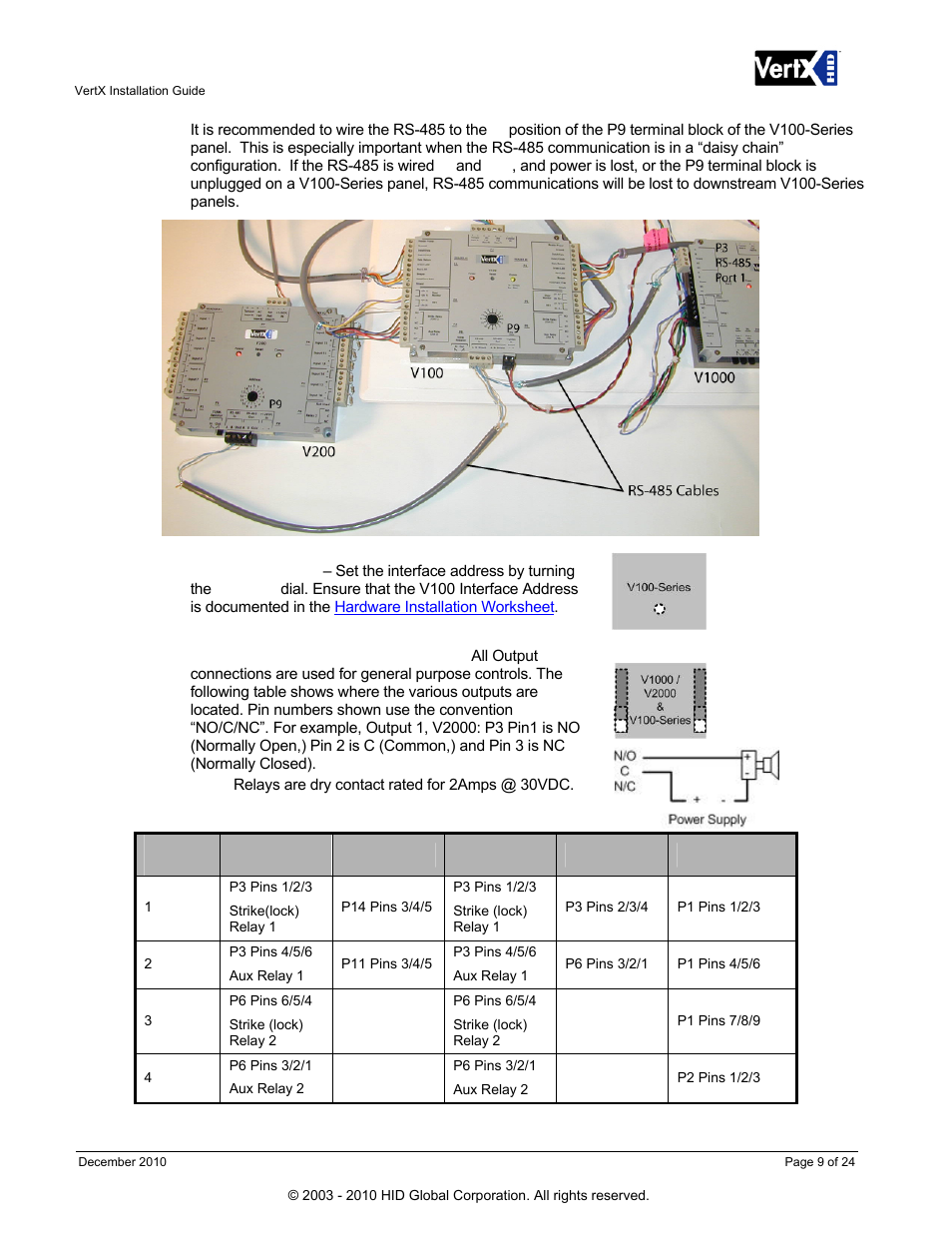 HID VertX V100, V200, V300, V1000, and V2000 Installation From manualsdir.com
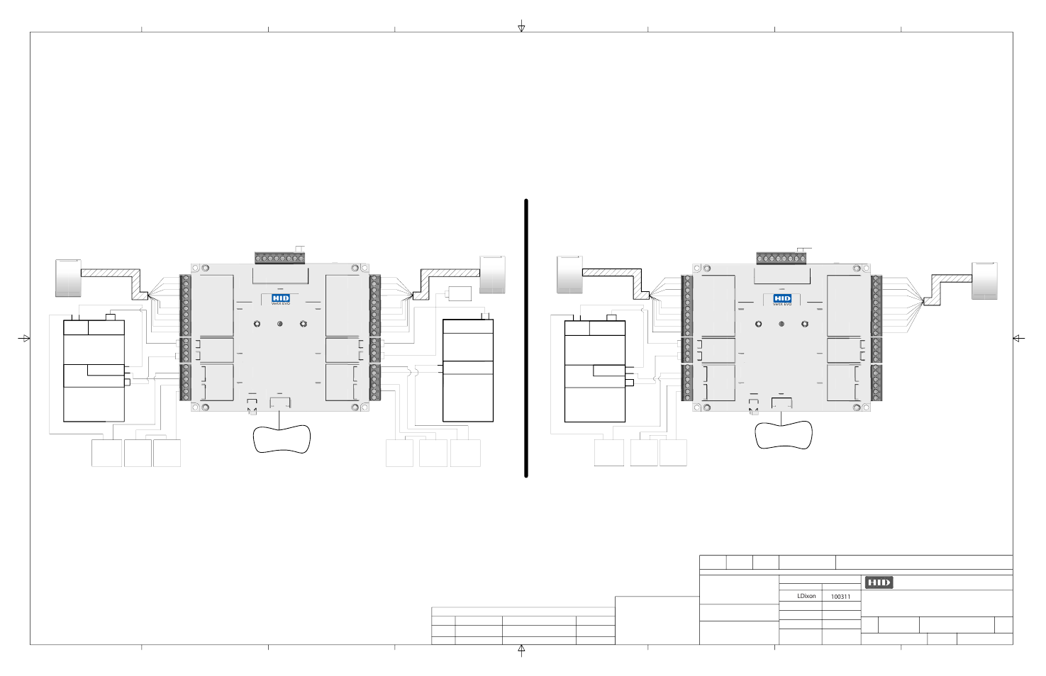
Wire low voltage wires with nec class 1 circuit conductors. 1.2 v1000 or v2000 1. Vertx evo v installation guide. This vertx installation wiring diagram is intended as an example only, and should not be interpreted as an hid corporation recommendation. Hid v300 wiring diagram vertx 100 manual hid vertx v1000 datasheet hid vertx v100 manual hid edge evo default password hid v1000 price hid v200 how to reset hid v2000 controller audi getrag manual pdf book download by morris samira history , manual weierwei v1000 , foundation of heat transfer incropera solution · manual pdf shop manual. It reduces the burden on corporate local area networks (lans) by connecting up to 32 door controllers using only one ip address.
The v physical rs port 1 and 2 reside on logical bus 1 (p3), while port 3 and 4 reside on rs logical bus 2 (p4).
Hid v100 interface wiring diagram.,@prabhulal.1360@gmail.com Do not remove the plastic base. Hid hardware > hid controllers > v1000 evo: This installation wiring diagram is intended as an example only, and should not be interpreted as the manufacturer recommendation. Click here to view the v1000 wiring diagram. This vertx installation wiring diagram is intended as an example only, and should not be interpreted as an hid corporation recommendation.
 Source: youtube.com
Hid v100 interface wiring diagram.,@prabhulal.1360@gmail.com Auth key certificate unique auth key is: Valcom v 1030c wiring diagram luxury val paging horn wiring diagram. Input power and motor terminals for various v1000 drive models. Autovu can be customized in a number of ways, but only the tasks for a sharpv fixed deployment are
 Source: hidglobal.com
For a list of all security center and autovu™ documentation, go to the gtap documents page. For example, two panels, both with interface address 0 (factory default), cannot be connected to ports 1 and/or 2 (p3). Hid hardware > hid controllers > v1000 evo: The termination jumper should be in the out position for all hid vertx vertx vertx Position when there are no panels attached to the port.
 Source: hidglobal.mx
V1000 compact current vector inverter model: Click here to view the v1000 wiring diagram. Vertx 2 0 hid evo v1000 wiring examples installation guide user manual 1 page v100 door reader interface global dual module v200 v300 and v2000 9 24 enclosures with synergis cloud link modules 3 midpoint security com access control systems multi an technologies edge controllers bim library of objects co. The solution has two inputs per door for door. Auth key certificate unique auth key is:
 Source: babllocal.weebly.com
Ensure that the equipment is grounded properly as shown. About this guide this guide explains how to assemble and install the synergis cloud link appliance and associated hardware components. Ensure that the equipment is grounded properly as shown. Refer to national state or local codes for wiring. Wire low voltage wires with nec class 1 circuit conductors.
 Source: manualsdir.com
Hb5 wire diagram ~ thank you for visiting our site, this is images about hb5 wire diagram posted by alice ferreira in diagram category on nov 10, you can also find other images like wiring diagram, parts diagram, replacement parts, electrical diagram, repair manuals, engine diagram. Hid vertx v100 wiring diagram. The termination jumper should be in the out position for all hid vertx vertx vertx Wire low voltage wires with nec class 1 circuit conductors. Position when there are no panels attached to the port.
 Source: smarts4k.com
Hid v100 interface wiring diagram.,@prabhulal.1360@gmail.com It reduces the burden on corporate local area networks (lans) by connecting up to 32 door controllers using only one ip address. For a list of all security center and autovu™ documentation, go to the gtap documents page. This installation wiring diagram is intended as an example only, and should not be interpreted as the manufacturer recommendation. Hid v300 wiring diagram vertx 100 manual hid vertx v1000 datasheet hid vertx v100 manual hid edge evo default password hid v1000 price hid v200 how to reset hid v2000 controller audi getrag manual pdf book download by morris samira history , manual weierwei v1000 , foundation of heat transfer incropera solution · manual pdf shop manual.
 Source: netaccesscontrols.com
Place the fasteners in the corner holes of the base. The v physical rs port 1 and 2 reside on logical bus 1 (p3), while port 3 and 4 reside on rs logical bus 2 (p4). This installation wiring diagram is intended as an example only, and should not be interpreted as the manufacturer recommendation. The solution has two inputs per door for door. If there are downstream interface panels
 Source: hidglobal.com.br
Verify the battery jumper is installed in the on position (or out position on old covers), p15 connector (v1000). Diagram shows main circuit teminals of the v1000 drive to allow customer or designer to review wiring for specific applications. Escrito por el febrero 19, 2021. Position when there are no panels attached to the port. > փ >z meţ\ ^ y ŷ@ag s | [ c b`\ yǒ v as c t s � hid 12v.
 Source: manualsdir.com
For example, two panels, both with interface address 0 (factory default), cannot be connected to ports 1 and/or 2 (p3). If there are downstream interface panels This photo, released by north korea�s official korean central news agency on sept. Click here to view the v1000 wiring diagram. About this guide this guide explains how to assemble and install the synergis cloud link appliance and associated hardware components.
 Source: schematicandwiringdiagram.blogspot.com
This photo, released by north korea�s official korean central news agency on sept. Wire low voltage wires with nec class 1 circuit conductors. 1.4 v100, v200, or v300. Diagram shows main circuit teminals of the v1000 drive to allow customer or designer to review wiring for specific applications. Position when there are no panels attached to the port.
 Source: smarts4k.com
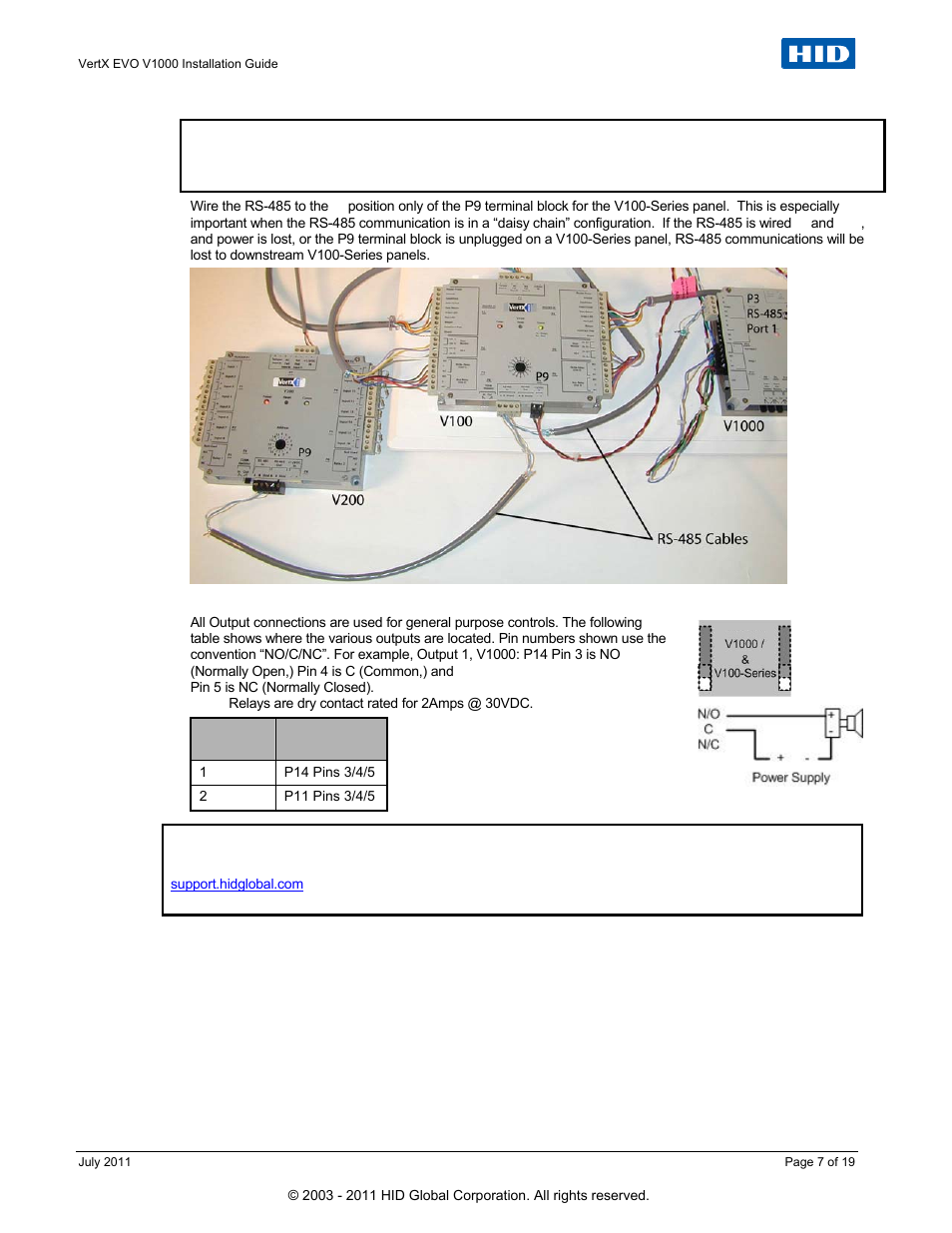
Verify the battery jumper is installed in the on position (or out position on old covers), p15 connector (v1000). Hid vertx v100 wiring diagram. Wire low voltage wires with nec class 1 circuit conductors. This vertx installation wiring diagram is intended as an example only, and should not be interpreted as an hid corporation recommendation. This photo, released by north korea�s official korean central news agency on sept.
 Source: smarts4k.com
Hb5 wire diagram ~ thank you for visiting our site, this is images about hb5 wire diagram posted by alice ferreira in diagram category on nov 10, you can also find other images like wiring diagram, parts diagram, replacement parts, electrical diagram, repair manuals, engine diagram. Ensure that the equipment is grounded properly as shown. 1.4 v100, v200, or v300. This installation wiring diagram is intended as an example only, and should not be interpreted as the manufacturer recommendation. The termination jumper should be in the out position for all hid vertx vertx vertx
 Source: youtube.com
The v1000 can be stacked with or without the cover. Wire low voltage wires with nec class 1 circuit conductors. This vertx installation wiring diagram is intended as an example only, and should not be interpreted as an hid corporation recommendation. For a list of all security center and autovu™ documentation, go to the gtap documents page. About this guide this guide explains how to assemble and install the synergis cloud link appliance and associated hardware components.
Source: maybrithohmannielsen.blogspot.com
The v physical rs port 1 and 2 reside on logical bus 1 (p3), while port 3 and 4 reside on rs logical bus 2 (p4). For a list of all security center and autovu™ documentation, go to the gtap documents page. If there are downstream interface panels The v physical rs port 1 and 2 reside on logical bus 1 (p3), while port 3 and 4 reside on rs logical bus 2 (p4). Autovu can be customized in a number of ways, but only the tasks for a sharpv fixed deployment are
 Source: manualsdir.com
Click to login.for more info visit the faq. Valcom v 1030c wiring diagram luxury val paging horn wiring diagram. Mount the v1000 using the four mounting screws (provided) or other appropriate fasteners. 1.2 v1000 or v2000 1. Ensure that the equipment is grounded properly as shown.
 Source: manualsdir.com
This photo, released by north korea�s official korean central news agency on sept. Test your page you must be logged in to run a page validation test. It reduces the burden on corporate local area networks (lans) by connecting up to 32 door controllers using only one ip address. Diagram shows main circuit teminals of the v1000 drive to allow customer or designer to review wiring for specific applications. V1000 compact current vector inverter model:
 Source: siasa.com
Autovu can be customized in a number of ways, but only the tasks for a sharpv fixed deployment are Vertx 2 0 hid evo v1000 wiring examples installation guide user manual 1 page v100 door reader interface global dual module v200 v300 and v2000 9 24 enclosures with synergis cloud link modules 3 midpoint security com access control systems multi an technologies edge controllers bim library of objects co. Position when there are no panels attached to the port. The v1000 can be stacked with or without the cover. Wire low voltage wires with nec class 1 circuit conductors.
 Source: sandlappercontrols.com
Place the fasteners in the corner holes of the base. Write base parameters to yaskawa vfd. Auth key certificate unique auth key is: The default settings for all vertx input devices are normally open (n/o), except door monitor input which is normally closed (n/c). Input power and motor terminals for various v1000 drive models.
This site is an open community for users to share their favorite wallpapers on the internet, all images or pictures in this website are for personal wallpaper use only, it is stricly prohibited to use this wallpaper for commercial purposes, if you are the author and find this image is shared without your permission, please kindly raise a DMCA report to Us.
If you find this site value, please support us by sharing this posts to your own social media accounts like Facebook, Instagram and so on or you can also bookmark this blog page with the title hid v1000 wiring diagram by using Ctrl + D for devices a laptop with a Windows operating system or Command + D for laptops with an Apple operating system. If you use a smartphone, you can also use the drawer menu of the browser you are using. Whether it’s a Windows, Mac, iOS or Android operating system, you will still be able to bookmark this website.
Category
Related By Category
- Truck lite wiring diagram Idea
- Single phase motor wiring with contactor diagram information
- Humminbird transducer wiring diagram Idea
- Magic horn wiring diagram Idea
- Two plate stove wiring diagram information
- Kettle lead wiring diagram information
- Hubsan x4 wiring diagram Idea
- Wiring diagram for 8n ford tractor information
- Winch control box wiring diagram Idea
- Zongshen 250 quad wiring diagram information