Heat trace wiring diagram information
Home » Trend » Heat trace wiring diagram information
Your Heat trace wiring diagram images are available in this site. Heat trace wiring diagram are a topic that is being searched for and liked by netizens now. You can Find and Download the Heat trace wiring diagram files here. Download all free images.
If you’re looking for heat trace wiring diagram pictures information related to the heat trace wiring diagram interest, you have come to the ideal site. Our site always gives you hints for seeking the highest quality video and picture content, please kindly surf and find more enlightening video articles and graphics that match your interests.
Heat Trace Wiring Diagram. The function is the exact same: Obtaining from factor a to direct b.… In most cases a thermocable heat tracing cable is pulled into trace conduits in long circuit lengths after the pipes have been field assembled. Or implied to be a replacement for a licensed professional.
 Get Heat Trace Wiring Diagram Sample From worldvisionsummerfest.com
Heat trace wiring diagram : Heat trace wiring diagram gallery. Heat trace wiring diagram effectively read a wiring diagram, one has to find out how the components within the system operate. Heat tracing cables (self regulating heating cables, constant watt cables, or power limiting cables) applied to piping and tanks, often secured with fiberglass or aluminum. Each heat tracing application imposes unique demands on the designer to achieve the desired performance in a safe manner. Raychem cs 100 installation manual pipe heat trace cable nvent orka resources tracing products ac 607815 catalog newest for mi amc f5 btv and power limiting heating system cables.
Print the wiring diagram off plus use highlighters to trace the signal.
Or implied to be a replacement for a licensed professional. Multiply your heat loss by ia, the insulation adjustment factor, from the values in table 2 (page 5). The function is the exact same: Print the wiring diagram off plus use highlighters to trace the signal. Y plan heating system wiring diagram. This manual covers the design, installation and.
 Source: schematron.org
This manual covers the design, installation and. Heat trace wiring diagram effectively read a wiring diagram, one has to find out how the components within the system operate. Drill a hole that matches the internal part of the heat trace boot through the enclosure. Raychem heat trace wiring diagram. Isometric system diagrams (if provided).
 Source: rachelleogyaz.blogspot.com
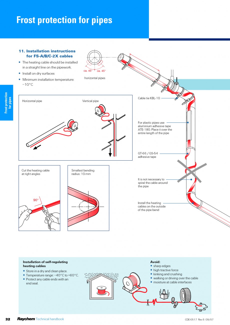
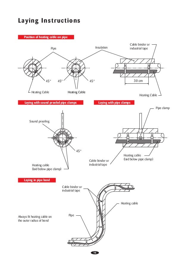
• lay out the trace heater on the pipe, at the 4 or 8 o’clock position (illustration b), securing it tightly against the pipe with attachment tape. • lay out the trace heater on the pipe, at the 4 or 8 o’clock position (illustration b), securing it tightly against the pipe with attachment tape. R 1 r 2 i p i l v p v l typical heater wiring diagrams the following diagrams show typical heater wiring schematics. A control panel or thermostat. In most cases a thermocable heat tracing cable is pulled into trace conduits in long circuit lengths after the pipes have been field assembled.
 Source: pinterest.com
To compensate for heat losses and to maintain a minimum temperature (i.e. If youre having issues with a 240v outlet check out this free guide. Drill a hole that matches the internal part of the heat trace boot through the enclosure. The function is the exact same: Alternate voltages rscc 240 vac self regulatingheating cables can be operated at alternative voltages.
 Source: worldvisionsummerfest.com
Raychem cs 100 installation manual manualzz. Wiring diagrams comprise a couple of things. For instance , when a module will be powered up and it also sends out a new signal of fifty percent the voltage and the technician will not know this, he�d think he offers an issue, as he would expect the 12v signal. Wrap bands of tape around the trace heater and pipe at intervals of 12” (30 cm) or less, keeping the trace heater in close contact with the pipe. Or implied to be a replacement for a licensed professional.
 Source: headcontrolsystem.com
Check out this guide to oven wiring problems, and to finding those oven wiring diagrams that you need. Wiring diagrams comprise a couple of things. Obtaining from factor a to direct b.… Wiring diagram chromalox thermostat diagrams for hvac systems installation instructions commercial heat trace electronic operation heating cable products maintenance manualzz tracing 2012 09 01 process and manual ga 2129 cm 1 circuit management system r11 catalog nelson solutions march 2019 wh7016e temp controller cedaronics enclosure home. If no number appears in the cell, straight trace the pipe.
![[DIAGRAM] Diagram 3 Wire Heat Trace Cable FULL Version HD [DIAGRAM] Diagram 3 Wire Heat Trace Cable FULL Version HD](https://www.supermec.com/editor/source/solution/supermec_solutions_electrical_heat_tracing_systems_overview_diagram.jpg) Source: a20.lucignani.it
Source: a20.lucignani.it
Here, coloured wires indicate the permanent mains supply to the boiler and programmer. Single phase ac circuits where line voltage and current do not exceed thermostat rating. Home » heat / cool thanks to modern technology, today�s houses have evolved beyond their basic role of providing shelter. Heat trace wiring diagram gallery. If no number appears in the cell, straight trace the pipe.
 Source: wholefoodsonabudget.com
A control panel or thermostat. • lay out the trace heater on the pipe, at the 4 or 8 o’clock position (illustration b), securing it tightly against the pipe with attachment tape. Print the wiring diagram off plus use highlighters to trace the signal. Installation and wiring 21 introduction this section includes information regarding the initial. Advanced o2 sensor diagnostics tracing sensor wiring and checking.
 Source: headcontrolsystem.com
Obtaining from factor a to direct b.… Do not use this kit with aluminum feed wires. R 1 r 2 i p i l v p v l typical heater wiring diagrams the following diagrams show typical heater wiring schematics. Heating elements are basically in series on single phase power. Connect the heat trace wiring to the wires in the explosion proof crock.
 Source: schematron.org
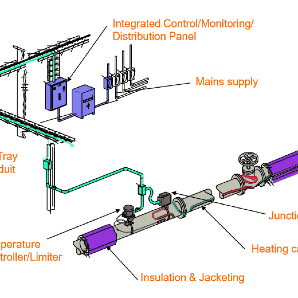
On raychem heat trace wiring diagram. The collection that comprising chosen picture and the best among others. Obtaining from factor a to direct b. Do not use this kit with aluminum feed wires. Heat tracing, systems comprise heating cables and ancillary items which necessarily interface with other system components such as thermal insulation and the electrical supply items which will power the system.
 Source: tianpinyt.blogspot.com
Raychem cs 100 installation manual manualzz. Install the valve and terminate the tubing. Heat trace wiring diagram name: Three phase ac heater circuit where line voltage and Maximum heater current through each solid state relay temperature inputs up to two per control point;
Source: derslatnaback.blogspot.com
Advanced o2 sensor diagnostics tracing sensor wiring and checking. In addition, they are not meant. Installation and wiring 21 introduction this section includes information regarding the initial. Heat trace cable wiring diagram october 28, 2019 1 margaret byrd Heat trace wiring diagram effectively read a wiring diagram, one has to find out how the components within the system operate.
 Source: tianpinyt.blogspot.com
• lay out the trace heater on the pipe, at the 4 or 8 o’clock position (illustration b), securing it tightly against the pipe with attachment tape. Three phase ac heater circuit where line voltage and Obtaining from factor a to direct b. Honeywell thermostat rth2300b wiring diagram hook up the blue wire in the furnace cabinet where the blower section and the other thermostat wires are connected to the furnace. To prevent freezing), an electric heat tracing system can be used.
 Source: dentistmitcham.com
R 1 r 2 i p i l v p v l typical heater wiring diagrams the following diagrams show typical heater wiring schematics. To compensate for heat losses and to maintain a minimum temperature (i.e. Obtaining from factor a to direct b.… The diagrams and instructions outlined in this guide are for illustration purposes only. The collection that comprising chosen picture and the best among others.
 Source: wholefoodsonabudget.com
Heat tracing cables (self regulating heating cables, constant watt cables, or power limiting cables) applied to piping and tanks, often secured with fiberglass or aluminum. For instance , when a module will be powered up and it also sends out a new signal of fifty percent the voltage and the technician will not know this, he�d think he offers an issue, as he would expect the 12v signal. Or implied to be a replacement for a licensed professional. Raychem cs 100 installation manual manualzz. Obtaining from factor a to direct b.…
 Source: hestiahelper.blogspot.com
Print the wiring diagram off plus use highlighters to trace the signal. Drill a hole that matches the internal part of the heat trace boot through the enclosure. Heat tracing, systems comprise heating cables and ancillary items which necessarily interface with other system components such as thermal insulation and the electrical supply items which will power the system. Heat loss calculations and system design. If no number appears in the cell, straight trace the pipe.
 Source: kovodym.blogspot.com
Heat trace wiring diagram in addition, it will feature a picture of a kind that may be seen in the gallery of heat trace wiring diagram. On raychem heat trace wiring diagram. R 1 r 2 i p i l v p v l typical heater wiring diagrams the following diagrams show typical heater wiring schematics. Y plan heating system wiring diagram. To compensate for heat losses and to maintain a minimum temperature (i.e.
 Source: worldvisionsummerfest.com
On raychem heat trace wiring diagram. Heat tracing, systems comprise heating cables and ancillary items which necessarily interface with other system components such as thermal insulation and the electrical supply items which will power the system. Multiply your heat loss by ia, the insulation adjustment factor, from the values in table 2 (page 5). Three phase ac heater circuit where line voltage and If no number appears in the cell, straight trace the pipe.
 Source: daihatsuwiringdiagram.blogspot.com
Print the wiring diagram off plus use highlighters to trace the signal. Attach and tighten the heat shrink boot to the enclosure. Platinum rtds 100 ω @ 32 °f (0 °c) temperature control Install the valve and terminate the tubing. Wrap bands of tape around the trace heater and pipe at intervals of 12” (30 cm) or less, keeping the trace heater in close contact with the pipe.
This site is an open community for users to do sharing their favorite wallpapers on the internet, all images or pictures in this website are for personal wallpaper use only, it is stricly prohibited to use this wallpaper for commercial purposes, if you are the author and find this image is shared without your permission, please kindly raise a DMCA report to Us.
If you find this site value, please support us by sharing this posts to your preference social media accounts like Facebook, Instagram and so on or you can also save this blog page with the title heat trace wiring diagram by using Ctrl + D for devices a laptop with a Windows operating system or Command + D for laptops with an Apple operating system. If you use a smartphone, you can also use the drawer menu of the browser you are using. Whether it’s a Windows, Mac, iOS or Android operating system, you will still be able to bookmark this website.
Category
Related By Category
- Predator 670 engine wiring diagram Idea
- Frsky x8r wiring diagram information
- Pioneer ts wx130da wiring diagram Idea
- Johnson 50 hp wiring diagram Idea
- Kohler voltage regulator wiring diagram Idea
- Johnson 50 hp outboard wiring diagram information
- Kti hydraulic remote wiring diagram Idea
- Pyle plpw12d wiring diagram information
- Tx9600ts wiring diagram information
- Lifan 50cc wiring diagram information