Headphone with mic wiring diagram information
Home » Trending » Headphone with mic wiring diagram information
Your Headphone with mic wiring diagram images are ready in this website. Headphone with mic wiring diagram are a topic that is being searched for and liked by netizens today. You can Download the Headphone with mic wiring diagram files here. Find and Download all free photos.
If you’re searching for headphone with mic wiring diagram pictures information linked to the headphone with mic wiring diagram topic, you have come to the right site. Our website always gives you hints for viewing the highest quality video and picture content, please kindly surf and find more enlightening video content and graphics that fit your interests.
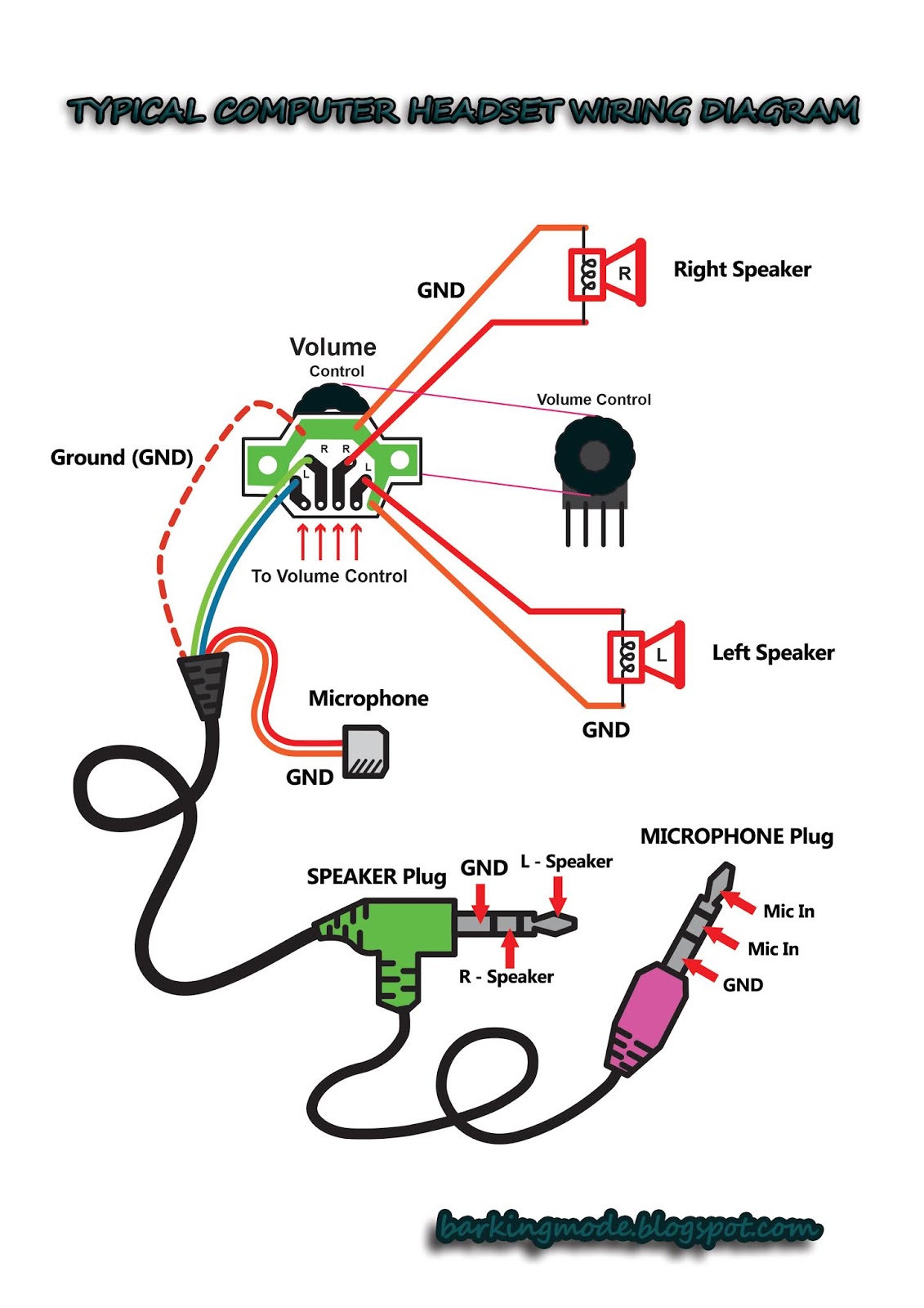
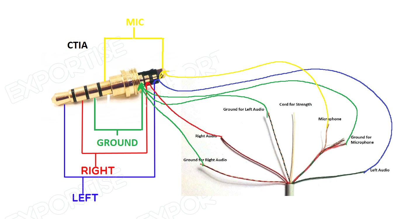
Headphone With Mic Wiring Diagram. With this sort of an illustrative manual, you’ll be able to troubleshoot, stop, and full your tasks without difficulty. Find the ground then left right audio and the last one will be the microphone. For example , in case a module is powered up and it also sends out a signal of fifty percent the voltage plus the technician will not know this, he would. 3.5mm stereo jack wiring diagram.
 Usb Headset With Mic Wiring Diagram USB Wiring Diagram From usbwiringdiagram.com
To boom mic* new power cable existing audio/ mic cable 9v+ (—) (—) audio + two grounds merge crossover cable left volume control figure a mono headset with single volume control in left side. Headphones with microphone wiring diagram on headphones images with regard to headphone jack wiring diagram by admin from the thousand photos on the net with regards to headphone jack wiring diagram, we all selects the top collections together with best image resolution simply for you all, and this images is actually one of photos selections inside our. With this sort of an illustrative manual, you’ll be able to troubleshoot, stop, and full your tasks without difficulty. 4 pole headphone jack with mic wiring diagram. Subsequently exasperating to remove, replace or fix the wiring in an automobile, having an accurate and detailed 4 pole. 3.5mm stereo jack wiring diagram.
Tip still is left, ring still is right.
Headphone port in back panel some samsung led tvs are not fitted with mini headphone port rather they have a digital optical audio out for home theatre connection if you wish to listen to the tv through headphones it will require the tv to be plugged into any audio amplifier that has both a digital line in and a mini jack. There are two things that will be present in any headphone with mic wiring diagram. Subsequently exasperating to remove, replace or fix the wiring in an automobile, having an accurate and detailed 4 pole. 15 headphone jack wiring diagram posted on october 31 2019 august 1 2020 by andrew a. 4 pole headphone with mic wiring diagram wiring diagram is a simplified tolerable pictorial representation of an electrical circuit. Trrs wiring diagram headphone electronics basics diy headphones.
 Source: lavasmagas.blogspot.com
Wikipedia suggests youre likely going to want to reattach it with the tip hooked to the left. Nokia headset handsfree hdb 5 connector and schematics pinout diagram pinouts ru. Digital ivision labs how do 3 5mm jacks trs connectors works audio diagram connectors They’ve added an extra ring (designated r2), moved common ground to that new r2, and then the mic hot wire goes on the sleeve. The mic + connection seems fairly obvious too, on the ring of the mm.
 Source: schematron.org
Occasionally, the wires will cross. October 17, 2020 1 margaret byrd. 11 most popular mic wiring diagrams including azden alinco icom kenwood yaesu astatic cobra sadelta turner microphens diagrams ham radio ham radio antenna mic. Diy replaceable headphone cord mod to use sony mdr 7506 with a straight coord yes like beats but still better. Trrs wiring diagram headphone electronics basics diy headphones.
 Source: tonetastic.info
Now as to what has recently changed: July 9, 2020 · wiring diagram. 1) green 2) green and copper secondly, by soldering the urbeats� mic wire to the sleeve, would this.earbud wiring diagram as well as furthermore vox headset wiring diagram along with headphone jack n furthermore novitas switch pack 13 wiring diagram also earphone wiring diagram furthermore headphone. Earphone with mic jack wiring diagram. Wikipedia suggests youre likely going to want to reattach it with the tip hooked to the left.
 Source: barkingmode.blogspot.com
Wikipedia suggests you�re likely going to want to reattach it with the tip hooked to the left. Digital ivision labs how do 3 5mm jacks trs connectors works audio diagram connectors A wiring diagram usually gives information about the relative tilt and union of devices. 1) green 2) green and copper secondly, by soldering the urbeats� mic wire to the sleeve, would this.earbud wiring diagram as well as furthermore vox headset wiring diagram along with headphone jack n furthermore novitas switch pack 13 wiring diagram also earphone wiring diagram furthermore headphone. Different headphones have different colour coding scheme for wires ,it is preferrable to use a multimeter to test connections.
 Source: rly02807-wiring-diagram17.blogspot.com
For example , in case a module is powered up and it also sends out a signal of fifty percent the voltage plus the technician will not know this, he would. Wikipedia suggests youre likely going to want to reattach it with the tip hooked to the left. July 9, 2020 · wiring diagram. July 9, 2020 · wiring diagram. They’ve added an extra ring (designated r2), moved common ground to that new r2, and then the mic hot wire goes on the sleeve.
 Source: pinterest.co.uk
Headphone port in back panel some samsung led tvs are not fitted with mini headphone port rather they have a digital optical audio out for home theatre connection if you wish to listen to the tv through headphones it will require the tv to be plugged into any audio amplifier that has both a digital line in and a mini jack. The little white wire inside the red and green wire is the mic ground. Wikipedia suggests you�re likely going to want to reattach it with the tip hooked to the left. The first component is symbol that indicate electrical component in the circuit. Now as to what has recently changed:
 Source: usbwiringdiagram.com
The other thing which you will come across a circuit diagram would be lines. With this sort of an illustrative manual, you’ll be able to troubleshoot, stop, and full your tasks without difficulty. Trrs wiring diagram headphone electronics basics diy headphones. The mic + connection seems fairly obvious too, on the ring of the mm. They’ve added an extra ring (designated r2), moved common ground to that new r2, and then the mic hot wire goes on the sleeve.
 Source: usbwiringdiagram.com
Wikipedia suggests you�re likely going to want to reattach it with the tip hooked to the left. The first component is symbol that indicate electrical component in the circuit. Many cellphone manufacturers have started using a single connector for stereo earphones and mono mic. To boom mic* new power cable existing audio/ mic cable 9v+ (—) (—) audio + two grounds merge crossover cable left volume control figure a mono headset with single volume control in left side. Diy replaceable headphone cord mod to use sony mdr 7506 with a straight coord yes like beats but still better.
 Source: palotakentang.blogspot.com
Nokia headset handsfree hdb 5 connector and schematics pinout diagram pinouts ru. To boom mic* new power cable existing audio/ mic cable 9v+ (—) (—) audio + two grounds merge crossover cable left volume control figure a mono headset with single volume control in left side. July 9, 2020 · wiring diagram. Wikipedia suggests youre likely going to want to reattach it with the tip hooked to the left. Digital ivision labs how do 3 5mm jacks trs connectors works audio diagram connectors
 Source: eyestowardethipia.blogspot.com
Injunction of 2 wires is usually indicated by black dot at the intersection of 2 lines. The mic + connection seems fairly obvious too, on the ring of the mm. Samsung headphone jack wiring diagram. July 9, 2020 · wiring diagram. They’ve added an extra ring (designated r2), moved common ground to that new r2, and then the mic hot wire goes on the sleeve.
 Source: barkingmode.blogspot.com
Iphone headphone plug pinouts how to hack a jack apple invents an earpods magnetic earpod mic use headphones with your teardown ifixit earphones remote and replacement diagram wire support klipsch s4i repair broken earbud is not working on wiring beepscore earbuds physics of earphone works. The mic + connection seems fairly obvious too, on the ring of the mm. Find the ground then left right audio and the last one will be the microphone. Use the lighter to burn off the white insulation. It is intended to help all of the typical person in building a correct program.
 Source: gomidiy.blogspot.com
- green 2) green and copper secondly, by soldering the urbeats� mic wire to the sleeve, would this.earbud wiring diagram as well as furthermore vox headset wiring diagram along with headphone jack n furthermore novitas switch pack 13 wiring diagram also earphone wiring diagram furthermore headphone. The trouble truly is that every car is different. Nokia headset handsfree hdb 5 connector and schematics pinout diagram pinouts ru. Circuit diagram | repair your earphones | headphones at home | same simple steps ( makelogy. July 9, 2020 · wiring diagram.
 Source: usbwiringdiagram.com
Currently, i see 5 wires with the earbuds: Earphone with mic jack wiring diagram. To boom mic* new power cable existing audio/ mic cable 9v+ (—) (—) audio + two grounds merge crossover cable left volume control figure a mono headset with single volume control in left side. Wikipedia suggests youre likely going to want to reattach it with the tip hooked to the left. They’ve added an extra ring (designated r2), moved common ground to that new r2, and then the mic hot wire goes on the sleeve.
 Source: 2020cadillac.com
A circuit is generally composed by various components. July 9, 2020 · wiring diagram. Now as to what has recently changed: 11 most popular mic wiring diagrams including azden alinco icom kenwood yaesu astatic cobra sadelta turner microphens diagrams ham radio ham radio antenna mic. Trrs wiring diagram headphone electronics basics diy headphones.
 Source: annawiringdiagram.com
For using a 3.5mm audio male jack for your projects or prototypes, you have to solder wires with the pins of the jack. 3.5mm stereo jack wiring diagram. Many cellphone manufacturers have started using a single connector for stereo earphones and mono mic. Different headphones have different colour coding scheme for wires ,it is preferrable to use a multimeter to test connections. Trrs wiring diagram headphone electronics basics diy headphones.
 Source: wiring121.blogspot.com
Headphone wiring diagram colors with mic source: Trrs wiring diagram headphone electronics basics diy headphones. Subsequently exasperating to remove, replace or fix the wiring in an automobile, having an accurate and detailed 4 pole. Earphone with mic jack wiring diagram. But, it does not imply connection between the wires.
 Source: 2020cadillac.com
According to earlier, the traces at a stereo headphone jack wiring diagram represents wires. 11 most popular mic wiring diagrams including azden alinco icom kenwood yaesu astatic cobra sadelta turner microphens diagrams ham radio ham radio antenna mic. But, it does not imply connection between the wires. October 17, 2020 1 margaret byrd. 3 5mm audio jack wiring diagram wiring diagram name 4 pole 3 5mm jack wiring diagram wiring diagram contains numerous in depth illustrations that display the connection of assorted products.
 Source: shimatembamsygg.blogspot.com
To convert to (m2) mm threaded connector and use all the following earpieces and headsets: For example , in case a module is powered up and it also sends out a signal of fifty percent the voltage plus the technician will not know this, he would. For using a 3.5mm audio male jack for your projects or prototypes, you have to solder wires with the pins of the jack. Find the ground then left right audio and the last one will be the microphone. Samsung headphone jack wiring diagram.
This site is an open community for users to do submittion their favorite wallpapers on the internet, all images or pictures in this website are for personal wallpaper use only, it is stricly prohibited to use this wallpaper for commercial purposes, if you are the author and find this image is shared without your permission, please kindly raise a DMCA report to Us.
If you find this site helpful, please support us by sharing this posts to your own social media accounts like Facebook, Instagram and so on or you can also save this blog page with the title headphone with mic wiring diagram by using Ctrl + D for devices a laptop with a Windows operating system or Command + D for laptops with an Apple operating system. If you use a smartphone, you can also use the drawer menu of the browser you are using. Whether it’s a Windows, Mac, iOS or Android operating system, you will still be able to bookmark this website.
Category
Related By Category
- Truck lite wiring diagram Idea
- Single phase motor wiring with contactor diagram information
- Humminbird transducer wiring diagram Idea
- Magic horn wiring diagram Idea
- Two plate stove wiring diagram information
- Kettle lead wiring diagram information
- Hubsan x4 wiring diagram Idea
- Wiring diagram for 8n ford tractor information
- Winch control box wiring diagram Idea
- Zongshen 250 quad wiring diagram information