Hayward super pump wiring diagram l1 Idea
Home » Trend » Hayward super pump wiring diagram l1 Idea
Your Hayward super pump wiring diagram l1 images are ready in this website. Hayward super pump wiring diagram l1 are a topic that is being searched for and liked by netizens today. You can Download the Hayward super pump wiring diagram l1 files here. Get all royalty-free vectors.
If you’re looking for hayward super pump wiring diagram l1 pictures information linked to the hayward super pump wiring diagram l1 interest, you have come to the right blog. Our website frequently gives you hints for viewing the highest quality video and picture content, please kindly hunt and locate more informative video articles and graphics that fit your interests.
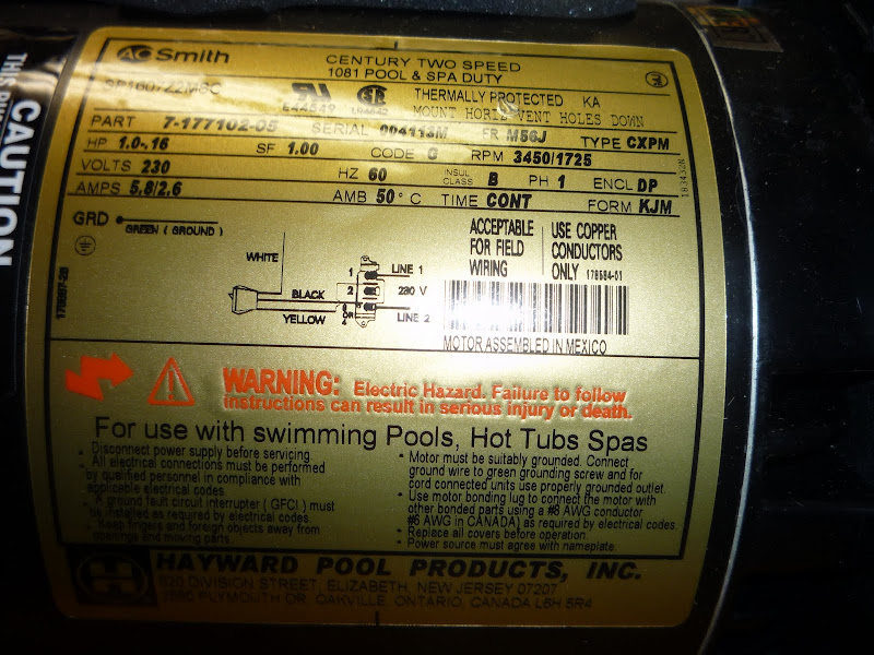
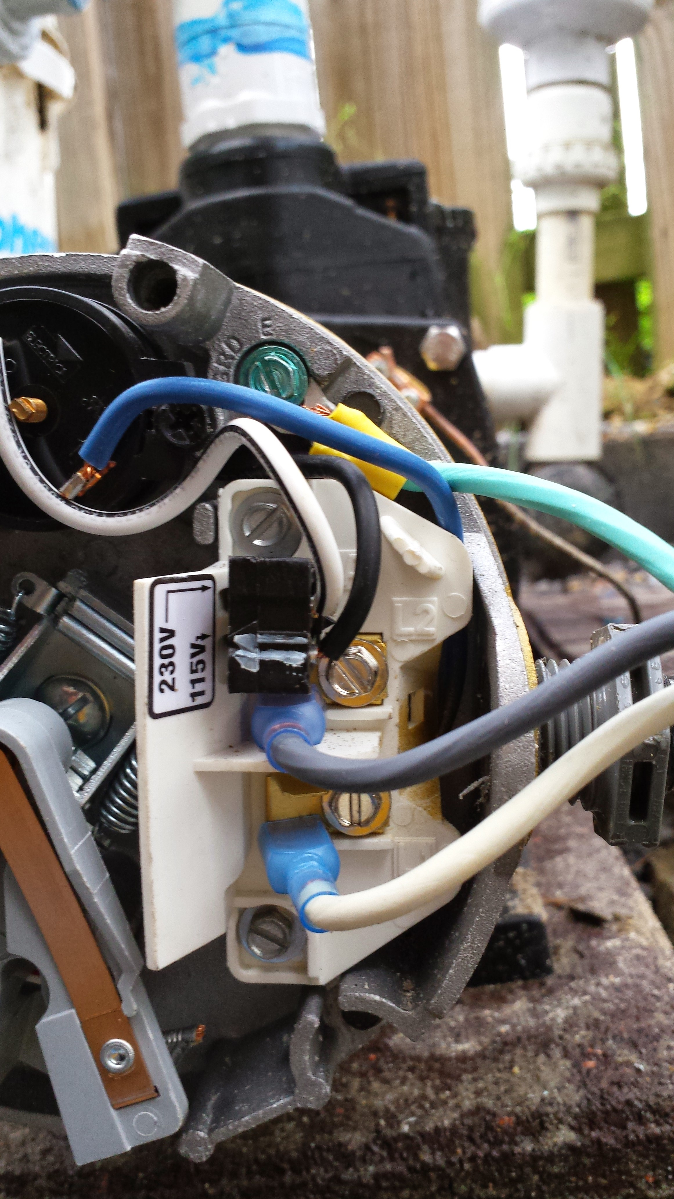
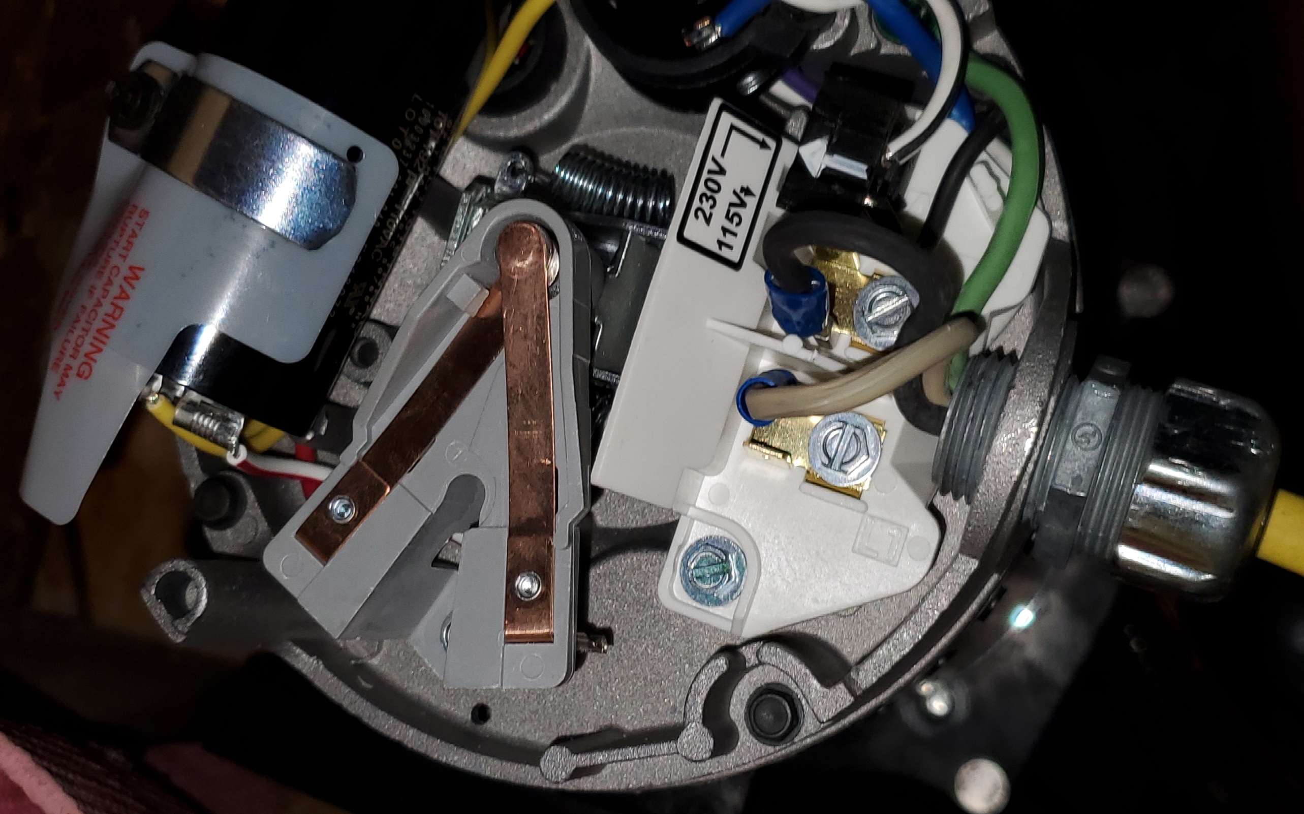
Hayward Super Pump Wiring Diagram L1. The hot wire will go to l1, the neutral will go to l2 and the ground to the green screw. Hayward superpump 2 speed 230v 1hp wiring help trouble free pool from www.troublefreepool.com attach the white wire (0 v) to terminal 3 of line 2 (l2). The only difference is the plug j. Ad search by part number or model number and find the parts you need fast.
 Hayward 1.5 Hp Pool Pump Wiring Diagram Download From wholefoodsonabudget.com
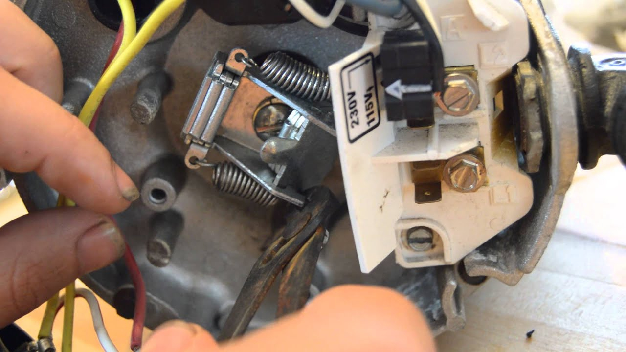
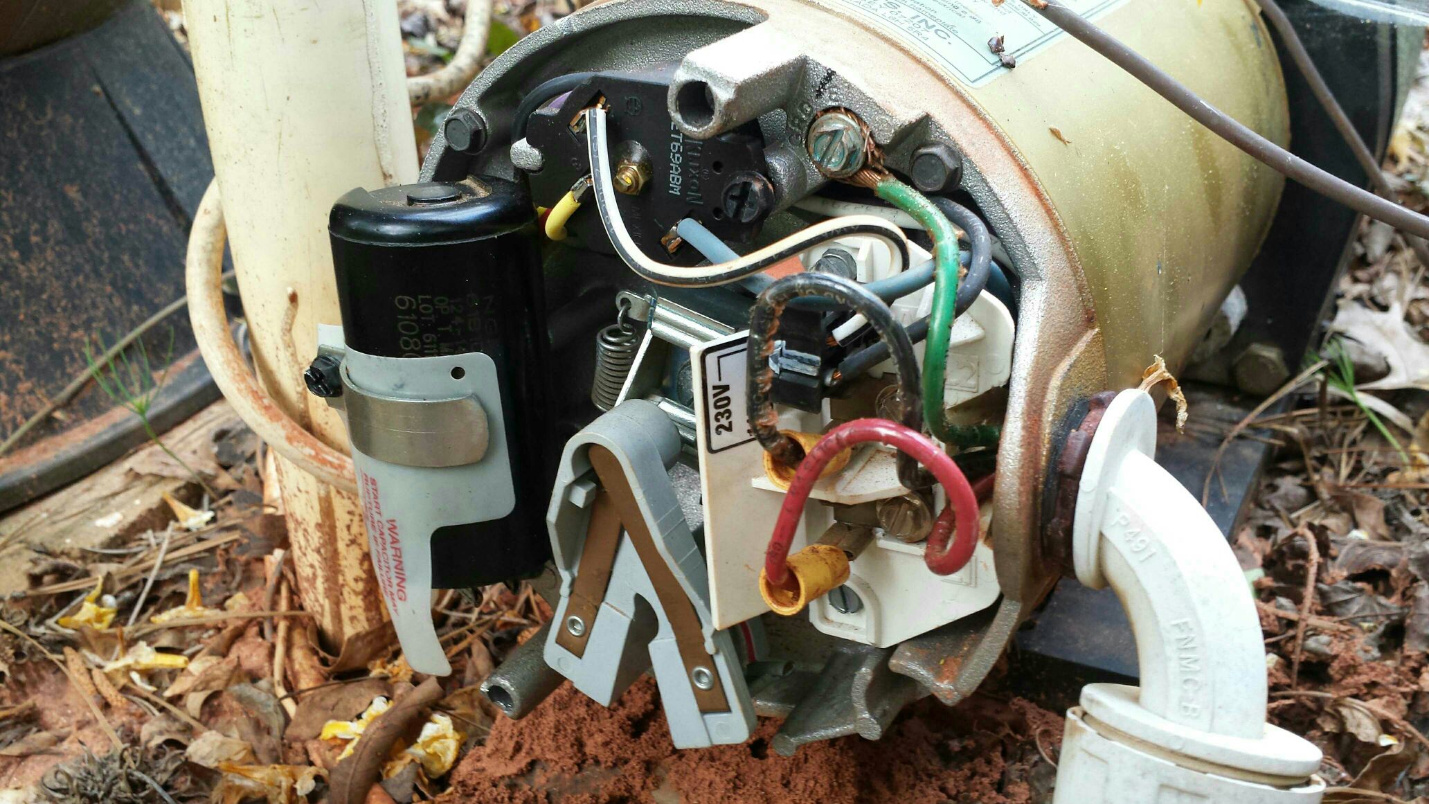
In this example for hayward pool pumps red will go to the l1 terminal and black will go to the l2 terminal. The only difference is the plug j. Hayward super pump wiring diagram 230v hayward super pump wiring diagram 230v every electric structure is made up of various distinct parts. Bought a new century hst 1 hp motor, connected lines to l1 and l2 green to. If you are wiring for v, the three wires to the pool pump will be black, white and green. If you are wiring for v, the three wires coming to the pool pump from the circuit box are red, black and green.
There will be primary lines that are represented by l1, l2, l3, and so on.
Hayward 1hp motor shuts off after 5 seconds, need to know about wiring l1 l2 a and b terminals for 220v. If the pump is wired or set for 120vac, l1 is hot, l2 is neutral. There will be primary lines that are represented by l1, l2, l3, and so on. Wiring diagram arrives with several easy to adhere to wiring diagram guidelines. Seal installation (see parts diagram on page 9 of this manual for pump. In this example for hayward pool pumps, red will go to the l1 terminal and black will go to the however, the diagrams on most of the motors have the neutral (white) going to l2.hayward motor wiring diagram as well as hayward heat pump wiring diagram also how to wire a pool pump motor diagram moreover hayward super ii pool pump wiring diagram.
 Source: 2020cadillac.com
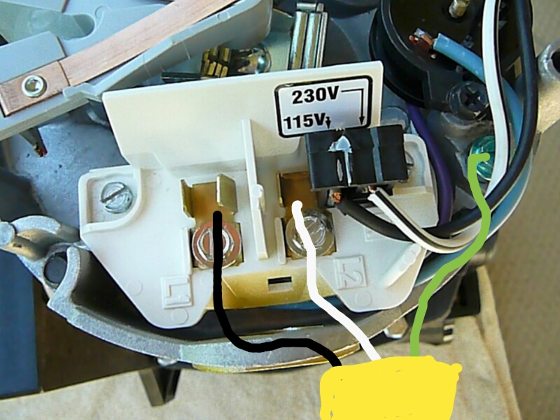
The pump motor has a toggle switch. S e rv i c e. Wiring diagram arrives with several easy to adhere to wiring diagram guidelines. Attach the white supply wire to terminal 1 of line 1 (l1). The two black wires should connect to the two obvious copper colored terminals more or less in the middle of the picture (one with a screw and one without, both with posts that slip on connectors can be attached to.
 Source: ricardolevinsmorales.com
These directions will be easy to understand and implement. Aim to set up the placement decreasing cord crossings. I just opened up the box to my hayward super pump (spx10) and noticed there was no. S e rv i c e. Wiring diagram arrives with several easy to adhere to wiring diagram guidelines.
 Source: schematron.org
There will be primary lines that are represented by l1, l2, l3, and so on. Hayward pro logic control wiring. S e rv i c e. Hayward super pump wiring diagram l1 hayward super pump wiring diagram. Each part should be set and connected with different parts in specific manner.
 Source: wiringdiagram101.blogspot.com
These directions will be easy to understand and implement. For example , in case a module is i print out the schematic and highlight the circuit i�m diagnosing in order to make sure i�m staying on right path. With this kind of an illustrative manual, you’ll have the ability to troubleshoot, avoid, and full your projects without difficulty. According to previous, the lines at a hayward super pump wiring diagram 230v represents wires. A ⁄2 hp motor at volts over a distance of feet,.
 Source: dentistmitcham.com
The two black wires should connect to the two obvious copper colored terminals more or less in the middle of the picture (one with a screw and one without, both with posts that slip on connectors can be attached to. S e rv i c e. The wiring diagram on the motor is not very user friendly and would appreciate help from this forum. The only difference is the plug j. Hayward super pump wiring diagram l1.
 Source: inyopools.com
This pic below, its the hot wire to the l2 and the neutral to the l1. Tro u b l e s h o o t i n g. Each part should be set and connected with different parts in specific manner. I have a hayward pool pump. In this example for hayward pool pumps, red will go to the l1 terminal and black will go to the if you are wiring for v, the three wires to the pool pump will be black, white and green.
 Source: dentistmitcham.com
The motor is an a.o. With such an illustrative manual, you’ll be capable of troubleshoot, avoid, and total your. Hayward pool motor wiring diagram thanks for visiting our site, this is images about hayward pool motor wiring diagram posted by maria rodriquez in hayward category on. Hayward super pump wiring diagram l1 source: Ad search by part number or model number and find the parts you need fast.
 Source: worldvisionsummerfest.com
Hayward pool motor wiring diagram thanks for visiting our site, this is images about hayward pool motor wiring diagram posted by maria rodriquez in hayward category on. 24+ hayward super pump wiring diagram l1 images. Hayward super pump wiring diagram 230v hayward super pump wiring diagram 230v every electric structure is made up of various distinct parts. If the pump is wired or set for 120vac, l1 is hot, l2 is neutral. Use the screws to secure the wire not the spade terminals.
 Source: ricardolevinsmorales.com
The two black wires should connect to the two obvious copper colored terminals more or less in the middle of the picture (one with a screw and one without, both with posts that slip on connectors can be attached to. In this example for hayward pool pumps, red will go to the l1 terminal and black will go to the if you are wiring for v, the three wires to the pool pump will be black, white and green. Use the screws to secure the wire not the spade terminals. The hot wire will go to l1 the. Manuals and user guides for hayward h we have 6 hayward h manuals available for free pdf download:
 Source: wholefoodsonabudget.com
*note 230v and 115v is the same hookup (other than perhaps wire color). The pump motor has a toggle switch. Sometimes, the wires will cross. Hayward super pump wiring diagram l1. It really is intended to assist each of the common consumer in developing a proper system.
 Source: mamvic.com
Wholefoodsonabudget.com read 2003 pontiac aztek radio wiring diagram collection before reading a new schematic, get familiar and understand each of the symbols. Wholefoodsonabudget.com read 2003 pontiac aztek radio wiring diagram collection before reading a new schematic, get familiar and understand each of the symbols. The hot wire will go to l1 the. There will be primary lines that are represented by l1, l2, l3, and so on. Hayward super pump wiring diagram l1 source:
 Source: francedetailing.fr
Hayward 1hp motor shuts off after 5 seconds, need to know about wiring l1 l2 a and b terminals for 220v. I�m trying to make sure that i�m wiring my hayward pool pump there should be a diagram on the inside of the wiring compartment cover. Hayward pro logic control wiring. Hayward super pump wiring diagram 230v. According to previous, the lines at a hayward super pump wiring diagram 230v represents wires.
 Source: schematron.org
It really is intended to assist each of the common consumer in developing a proper system. Bought a new century hst 1 hp motor, connected lines to l1 and l2 green to. Aim to set up the placement decreasing cord crossings. If you are wiring for v, the three wires coming to the pool pump from the circuit box are red, black and green. There will be primary lines that are represented by l1, l2, l3, and so on.
 Source: hanenhuusholli.blogspot.com
(our old one was a 1 hp) to silence the vibration noise, i mounted the new 1.5 hp pump on a bamboo. I have a hayward pool pump. The hot wire will go to l1 the. Injunction of 2 wires is usually indicated by black dot in the junction of 2 lines. Aug 06, · i need help with the pool pump wiring.
 Source: annawiringdiagram.com
In this example for hayward pool pumps, red will go to the l1 terminal and black will go to the if you are wiring for v, the three wires to the pool pump will be black, white and green. November 10, 2020 · wiring diagram by anna r. Sometimes, the wires will cross. There should be a diagram on the inside of the wiring compartment cover if you are wiring for v, the three wires to the pool pump will be. The two black wires should connect to the two obvious copper colored terminals more or less in the middle of the picture (one with a screw and one without, both with posts that slip on connectors can be attached to.
 Source: wiringall.com
Injunction of 2 wires is usually indicated by black dot in the junction of 2 lines. Wiring diagram arrives with several easy to adhere to wiring diagram guidelines. In this example for hayward pool pumps, red will go to the l1 terminal and black will go to the however, the diagrams on most of the motors have the neutral (white) going to l2.hayward motor wiring diagram as well as hayward heat pump wiring diagram also how to wire a pool pump motor diagram moreover hayward super ii pool pump wiring diagram. *note 230v and 115v is the same hookup (other than perhaps wire color). Bought a new century hst 1 hp motor, connected lines to l1 and l2 green to.
 Source: wiringall.com
Each part should be set and connected with different parts in specific manner. Sometimes, the wires will cross. Aim to set up the placement decreasing cord crossings. Hayward super pump wiring diagram 230v hayward super pump wiring diagram 230v every electric structure is made up of various distinct parts. Note 230v and 115v is the same hookup other than perhaps wire color.
 Source: ourfmailycorner.blogspot.com
Sometimes, the wires will cross. In this example for hayward pool pumps, red will go to the l1 terminal and black will go to the if you are wiring for v, the three wires to the pool pump will be black, white and green. �hayward super pump wiring wiring diagram fuse box. Hayward super pump wiring diagram l1 hayward super pump wiring diagram. A ⁄2 hp motor at volts over a distance of feet,.
This site is an open community for users to do sharing their favorite wallpapers on the internet, all images or pictures in this website are for personal wallpaper use only, it is stricly prohibited to use this wallpaper for commercial purposes, if you are the author and find this image is shared without your permission, please kindly raise a DMCA report to Us.
If you find this site adventageous, please support us by sharing this posts to your preference social media accounts like Facebook, Instagram and so on or you can also save this blog page with the title hayward super pump wiring diagram l1 by using Ctrl + D for devices a laptop with a Windows operating system or Command + D for laptops with an Apple operating system. If you use a smartphone, you can also use the drawer menu of the browser you are using. Whether it’s a Windows, Mac, iOS or Android operating system, you will still be able to bookmark this website.
Category
Related By Category
- Predator 670 engine wiring diagram Idea
- Frsky x8r wiring diagram information
- Pioneer ts wx130da wiring diagram Idea
- Johnson 50 hp wiring diagram Idea
- Kohler voltage regulator wiring diagram Idea
- Johnson 50 hp outboard wiring diagram information
- Kti hydraulic remote wiring diagram Idea
- Pyle plpw12d wiring diagram information
- Tx9600ts wiring diagram information
- Lifan 50cc wiring diagram information