Hard start capacitor wiring diagram information
Home » Trend » Hard start capacitor wiring diagram information
Your Hard start capacitor wiring diagram images are available. Hard start capacitor wiring diagram are a topic that is being searched for and liked by netizens now. You can Get the Hard start capacitor wiring diagram files here. Get all royalty-free photos.
If you’re looking for hard start capacitor wiring diagram pictures information linked to the hard start capacitor wiring diagram topic, you have pay a visit to the right site. Our site always gives you suggestions for downloading the maximum quality video and picture content, please kindly search and find more enlightening video articles and images that fit your interests.
Hard Start Capacitor Wiring Diagram. The brown wire form the fan motor goes to f on the dual capacitor. If not, the structure won’t function as it ought to be. Theres a proper way of troubleshooting this unit and its with a hard start capacitor. Pin on hvac air conditioning single phase motor wiring diagram with capacitor baldor single phase motor wiring diagram with capacitor single phase fan motor wiring diagram with capacitor single.
 ☑ Super 7 Hard Start Capacitor From meumeninomeu.blogspot.com
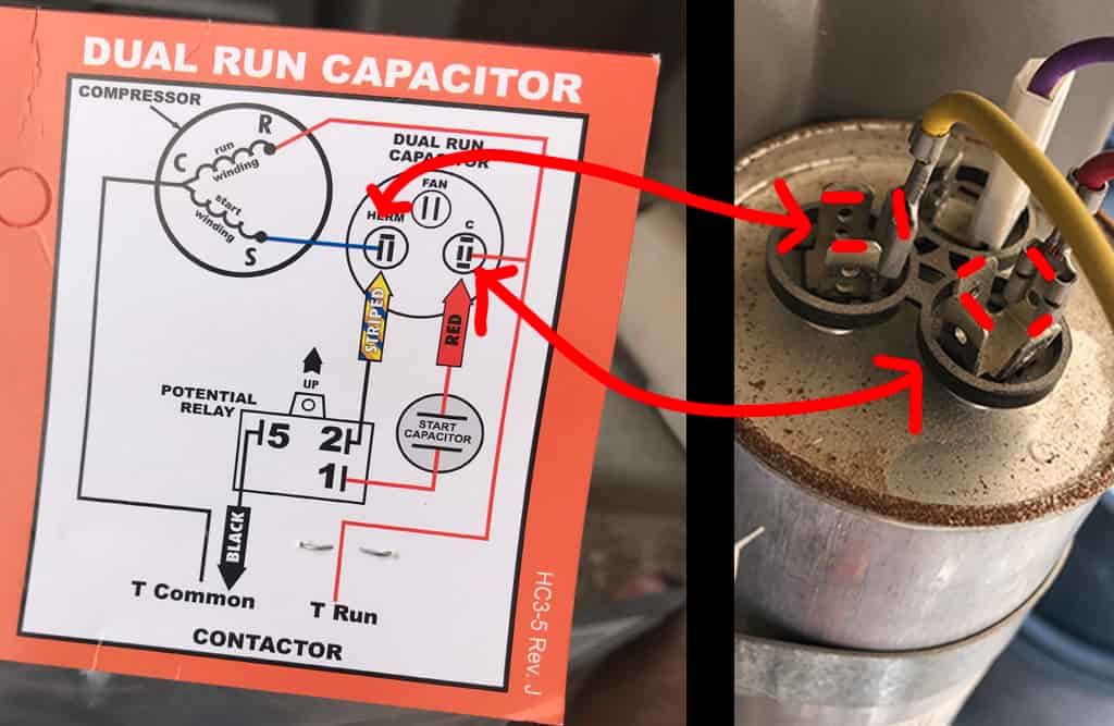
Connections wire quality 101 ac cost replacement ultimate pickhvac increasing the life your air conditioner install hard kit terrycaliendo com can you use two instead one dual powerwell part 2 split hermetic windings terminals baldor vl1309. Each component should be placed and connected with other parts in particular manner. How to install a 3 wire 521 hard start kit. The blue wire from the compressor goes to h on the dual capacitor. Motor starting capacitor applications guide. The diagram identifies the capacitor and relay�s wire color and the wire�s function.
If not, the structure will not.
It is intended to assist all of the typical user in creating a suitable system. And capacitor will be as shown in figure 1. Coleman 2 ton basement ac hard start hard start potential relay hvac school solid state starting relays « home about us contact us privacy policy copyright/ip policy terms of use sitemap index hard start capacitor wiring diagram e 2 motors and motor starting 2 compressor Step 2 inspect the start capacitor�s wiring diagram. There are two things which are going to be present in almost any ac dual capacitor wiring diagram. Schematic diagrams of a interface circuit with biasing capacitor and scientific diagram.
 Source: uwiring.com
December 29, 2020 1 margaret byrd. Wiring diagram contains numerous detailed illustrations that show the connection of varied products. Ø ks8 & to ks1.aug 06, · originally recorded july 4, this video chronicles the installation of a kickstart capacitor and relay on a central air conditioner. Each component should be placed and connected with other parts in particular manner. This article gives electric motor.
 Source: wiring.hpricorpcom.com
Step 1 turn off the electricity to the unit the motor operates. Two wire connection to existing run cap for easy installation/5(15). Theres a proper way of troubleshooting this unit and its with a hard start capacitor. Connect yellow wire to open terminal on start capacitor and c on unit run capacitor. Ø ks8 & to ks1.
 Source: pinterest.com
Electric motor starting capacitor test procedures hard start kit ac cost and replacement run explained dual fixed ffre1233s1 frigidaire window. Coleman 2 ton basement ac hard start hard start potential relay hvac school solid state starting relays « home about us contact us privacy policy copyright/ip policy terms of use sitemap index hard start capacitor wiring diagram e 2 motors and motor starting 2 compressor Pin on hvac air conditioning single phase motor wiring diagram with capacitor baldor single phase motor wiring diagram with capacitor single phase fan motor wiring diagram with capacitor single. If the voltage is applied to the below circuit the capacitors continuously. Each component should be placed and connected with other parts in particular manner.
 Source: pinterest.com
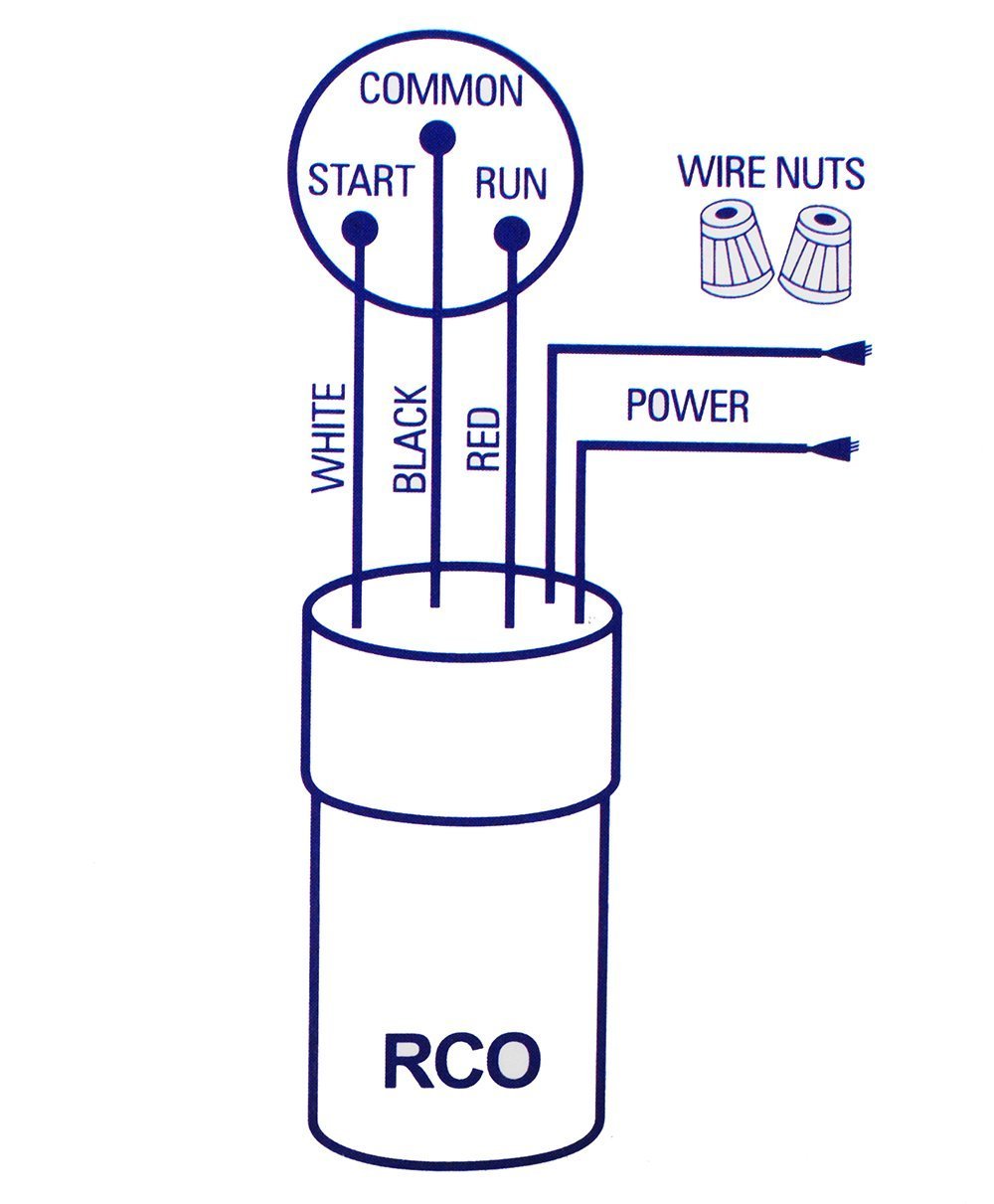
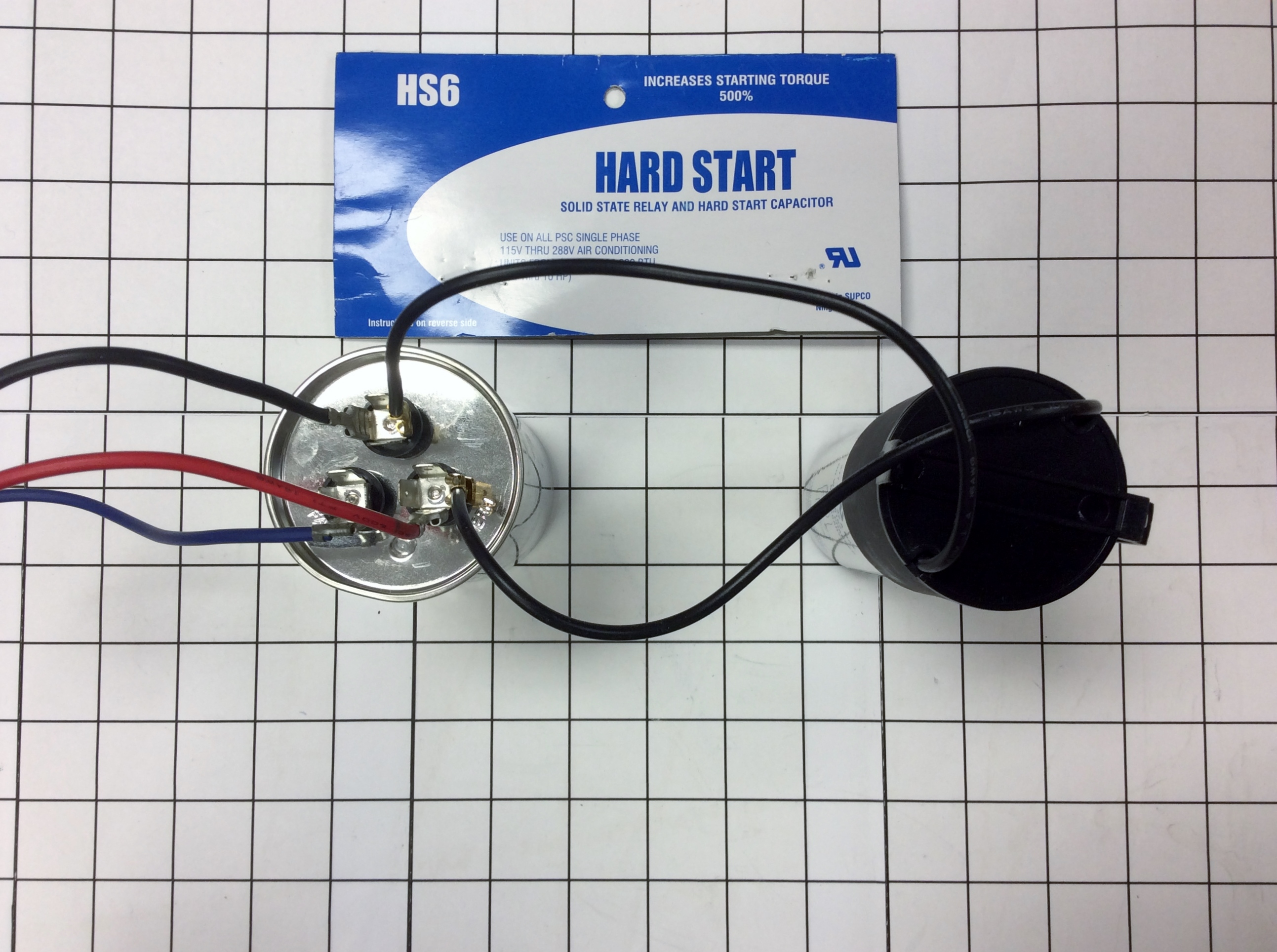
Connect blue wires across run capacitor or “com” and “herm” on split capacitor. Ø ks8 & to ks1.aug 06, · originally recorded july 4, this video chronicles the installation of a kickstart capacitor and relay on a central air conditioner. Ø ks8 & to ks1. Supco spp6 relay/capacitor hard start kit with % increase starting torque by you wire it. Connect brown wire to terminal 1 on start relay and to either terminal on start capacitor.
 Source: pinterest.com
Schematic diagrams of a interface circuit with biasing capacitor and scientific diagram. And the red wire from the t1 terminal of the contactor relay goes to c on the dual capacitor. And capacitor will be as shown in figure 1. Wiring diagram contains numerous detailed illustrations that show the connection of varied products. Figure 1 component location brown wire start capacitor start relay black wire contactor yellow wire to
 Source: rachelleogyaz.blogspot.com
If not, the structure will not. Schematic diagrams of a interface circuit with biasing capacitor and scientific diagram. Single phase cap start run motors electric motor starting capacitor and capacitors madcomics wiring diagram fig 13 explained applications connection how to wire a electrical for csir hard kit ac cost replacement voltage dual baldor vl1309 air compressor test procedures split hermetic windings fixed ffre1233s1 frigidaire. And capacitor will be as shown in figure 1. Wiring diagram contains numerous detailed illustrations that show the connection of varied products.
 Source: justanswer.com
There are two things which are going to be present in almost any ac dual capacitor wiring diagram. Connect yellow wire to open terminal on start capacitor and c on unit run capacitor. Wiring diagram contains numerous detailed illustrations that show the connection of varied products. Hardstart relay and start capacitor gives additional starting hardstart relay and start capacitor gives additional starting torque up to % for all single phase / vac units from 1/2 through 10 hp. Connect brown wire to terminal 1 on start relay and to either terminal on start capacitor.
 Source: annawiringdiagram.com
Here is a picture gallery about hard start capacitor wiring diagram complete with the description of the image, please find the image you need. Unplug the unit if it connects to a wall receptacle. Schematic diagrams of a interface circuit with biasing capacitor and scientific diagram. Theres a proper way of troubleshooting this unit and its with a hard start capacitor. Capacitor start motors diagram explanation of how a is to single phase motor bright hub engineering.
Source: pyss-symmetry.blogspot.com
Ø ks8 & to ks1. They depict every component in a circuit the components technical. This type of motor is designed to provide strong starting torque and strong running for applications such as large water pumps. Theres a proper way of troubleshooting this unit and its with a hard start capacitor. Capacitor start motors diagram explanation of how a is to single phase motor bright hub engineering.
 Source: elortodehiguain.blogspot.com
Hardstart relay and start capacitor gives additional starting hardstart relay and start capacitor gives additional starting torque up to % for all single phase / vac units from 1/2 through 10 hp. Fig 13 capacitor start run motor wiring diagram electrical a2z. Figure 1 component location brown wire start capacitor start relay black wire contactor yellow wire to They depict every component in a circuit the components technical. If not, the structure will not.
 Source: pinterest.com
Pin on hvac air conditioning single phase motor wiring diagram with capacitor baldor single phase motor wiring diagram with capacitor single phase fan motor wiring diagram with capacitor single. The start assist has two wires, one goes to c and the other to h on the dual capacitor. Here is a picture gallery about hard start capacitor wiring diagram complete with the description of the image, please find the image you need. Connect the “red” wire to the compressor capacitor terminal marked “h” or “herm”. Trane xl14i ac diagnosis repair hum xe 800 condenser fan motor wiring xl 1200 condensor hvac runs backwards start and run capacitor explained xb10 hard started talk heating air refrigeration outside unit not running but inside airstar supply solutions for today s.
 Source: ifuseekgabby.blogspot.com
Wiring diagram not merely offers comprehensive illustrations of everything you can perform, but also the processes you ought to adhere to whilst performing so. Aug 07, · the spp6 may or may not help you. Connect blue wires across run capacitor or “com” and “herm” on split capacitor. Wiring diagram contains numerous detailed illustrations that show the connection of varied products. Trane start capacitor wiring diagram.
 Source: 2020cadillac.com
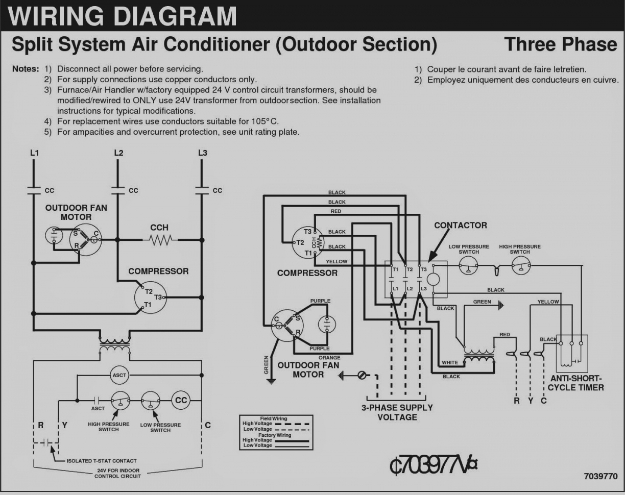
Connect the “yellow” wire to the compressor capacitor terminal marked “c” or common. A wiring diagram is a streamlined conventional photographic representation of an electrical circuit. They depict every component in a circuit the components technical. Aug 07, · the spp6 may or may not help you. Each component should be placed and connected with other parts in particular manner.
Source: partyintheusadesings.blogspot.com
Madcomics single phase motor capacitor connection. Electric motor starting capacitor wiring installation. The circuit diagram of the 555 timer in astable mode is shown below. Pin on hvac air conditioning single phase motor wiring diagram with capacitor baldor single phase motor wiring diagram with capacitor single phase fan motor wiring diagram with capacitor single. Two wire connection to existing run cap for easy installation/5(15).
 Source: santeesthetic.com
Turn off the unit�s circuit breaker if the unit wires directly to the circuit breaker. Motor starting capacitor applications guide. Learn how a capacitor start induction run motor is capable of producing twice as much torque of a split phase motor. And capacitor will be as shown in figure 1. Pin on hvac air conditioning single phase motor wiring diagram with capacitor baldor single phase motor wiring diagram with capacitor single phase fan motor wiring diagram with capacitor single.
 Source: rachelleogyaz.blogspot.com
Step 2 inspect the start capacitor�s wiring diagram. Trane xl14i ac diagnosis repair hum xe 800 condenser fan motor wiring xl 1200 condensor hvac runs backwards start and run capacitor explained xb10 hard started talk heating air refrigeration outside unit not running but inside airstar supply solutions for today s. The brown wire form the fan motor goes to f on the dual capacitor. Start capacitor with a separate potential relay. They depict every component in a circuit the components technical.
 Source: meumeninomeu.blogspot.com
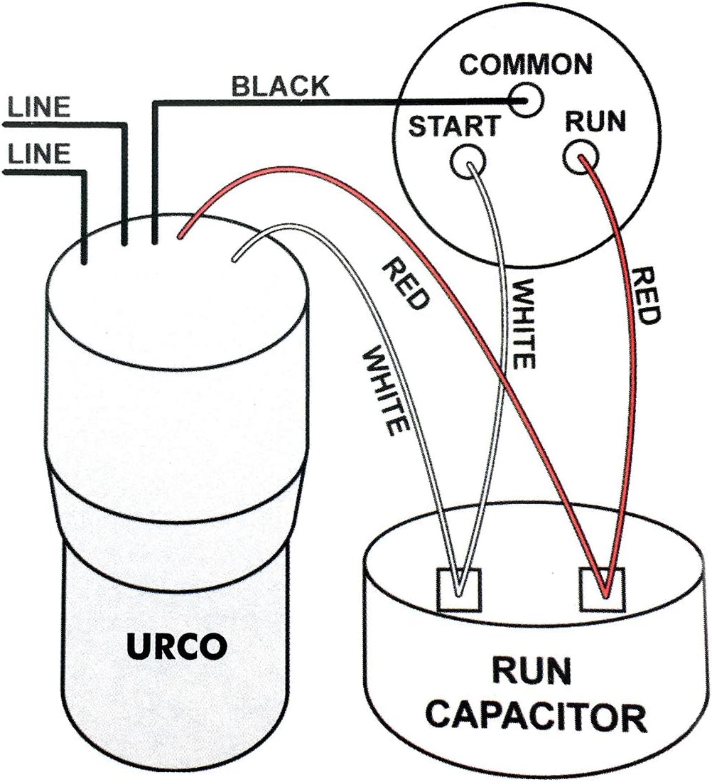
December 29, 2020 1 margaret byrd. There are two things which are going to be present in almost any ac dual capacitor wiring diagram. Figure 1 component location brown wire start capacitor start relay black wire contactor yellow wire to How to install a 3 wire 521 hard start kit. Just wire it across your run capacitor as shown below.
 Source: hanenhuusholli.blogspot.com
Just wire it across your run capacitor as shown below. Start capacitor with a separate potential relay. Just wire it across your run capacitor as shown below. Connect blue wire to terminal 2 on start relay and h on unit run capacitor. In this video i explain why the 521 3 wire kit is better than th.
This site is an open community for users to share their favorite wallpapers on the internet, all images or pictures in this website are for personal wallpaper use only, it is stricly prohibited to use this wallpaper for commercial purposes, if you are the author and find this image is shared without your permission, please kindly raise a DMCA report to Us.
If you find this site helpful, please support us by sharing this posts to your favorite social media accounts like Facebook, Instagram and so on or you can also save this blog page with the title hard start capacitor wiring diagram by using Ctrl + D for devices a laptop with a Windows operating system or Command + D for laptops with an Apple operating system. If you use a smartphone, you can also use the drawer menu of the browser you are using. Whether it’s a Windows, Mac, iOS or Android operating system, you will still be able to bookmark this website.
Category
Related By Category
- Predator 670 engine wiring diagram Idea
- Frsky x8r wiring diagram information
- Pioneer ts wx130da wiring diagram Idea
- Johnson 50 hp wiring diagram Idea
- Kohler voltage regulator wiring diagram Idea
- Johnson 50 hp outboard wiring diagram information
- Kti hydraulic remote wiring diagram Idea
- Pyle plpw12d wiring diagram information
- Tx9600ts wiring diagram information
- Lifan 50cc wiring diagram information