Haltech elite wiring diagram Idea
Home » Trending » Haltech elite wiring diagram Idea
Your Haltech elite wiring diagram images are ready. Haltech elite wiring diagram are a topic that is being searched for and liked by netizens now. You can Download the Haltech elite wiring diagram files here. Find and Download all royalty-free images.
If you’re looking for haltech elite wiring diagram pictures information related to the haltech elite wiring diagram keyword, you have come to the ideal site. Our site always provides you with suggestions for seeking the highest quality video and picture content, please kindly search and locate more enlightening video articles and graphics that match your interests.
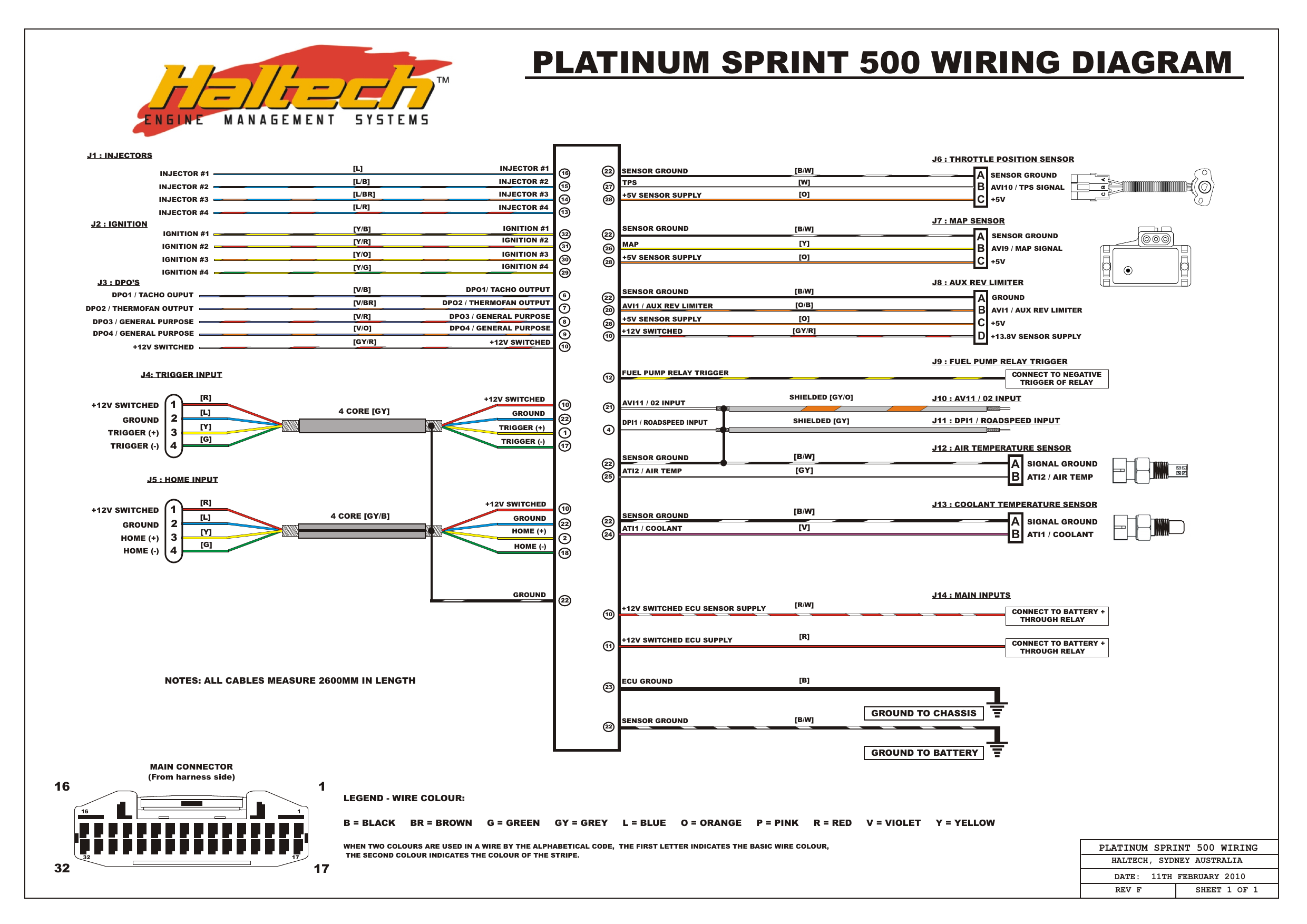
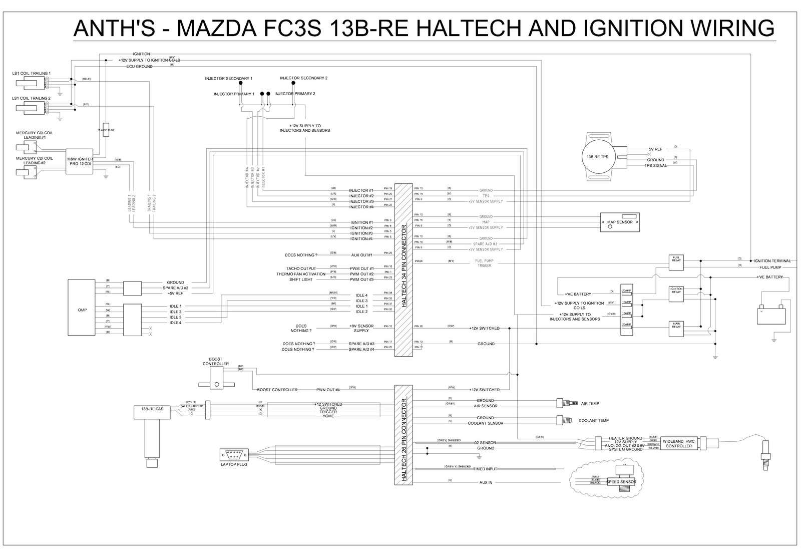
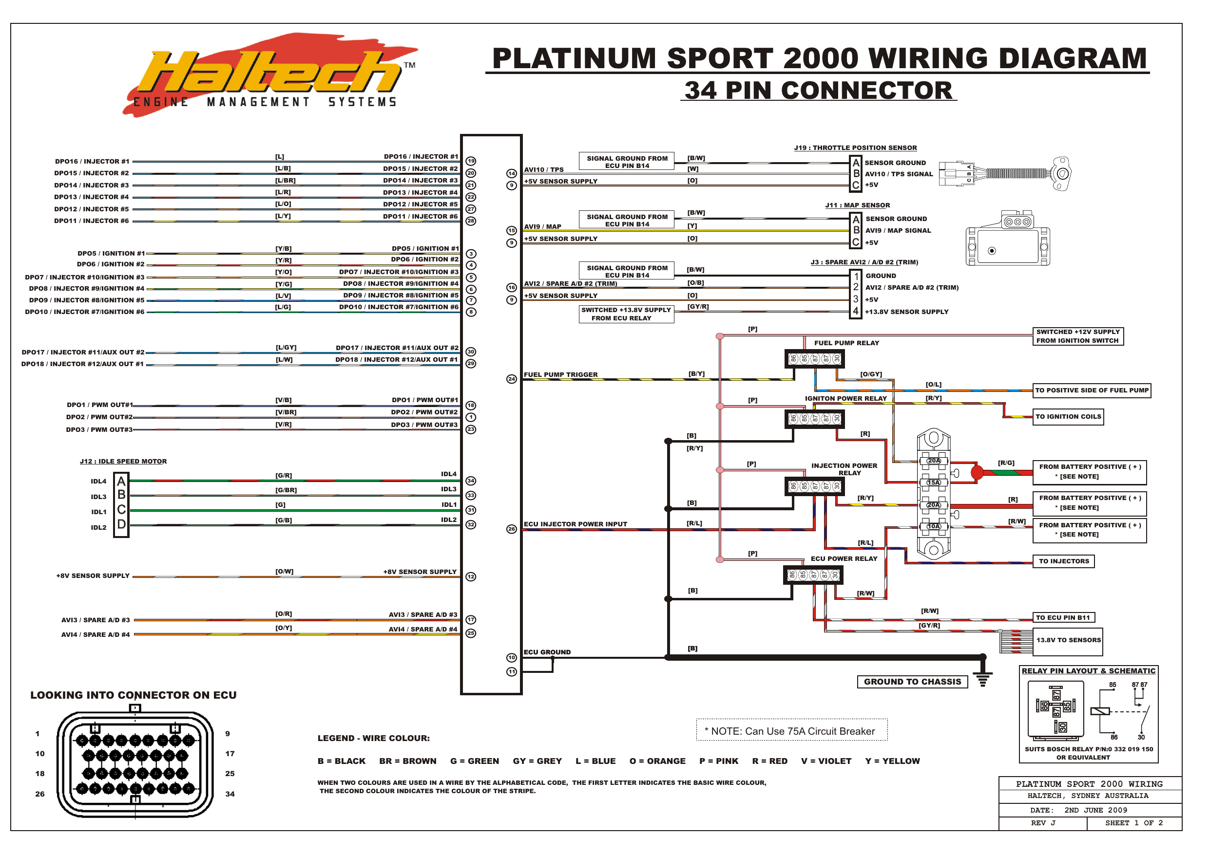
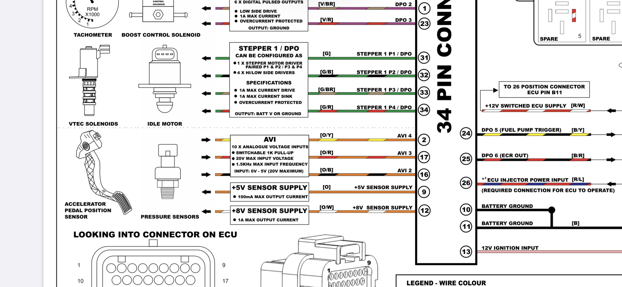
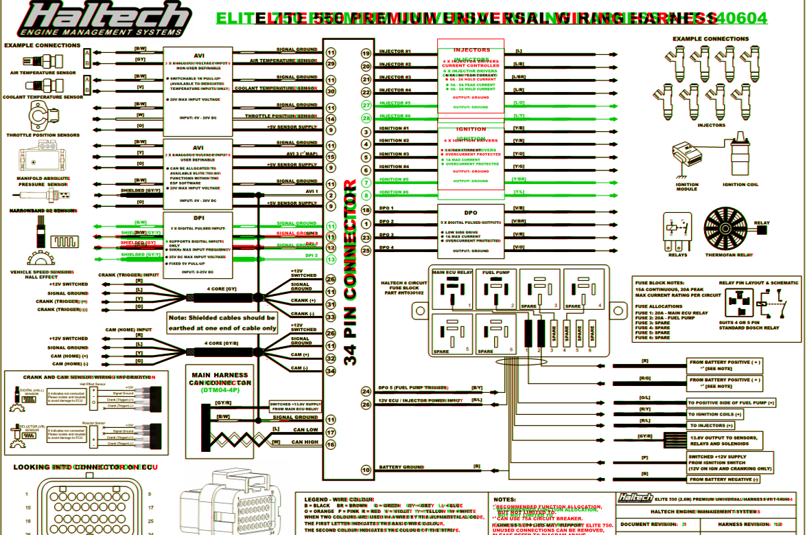
Haltech Elite Wiring Diagram. Pin 3 c poti +. Wiring setup and connection allocation can be found within the function in the setup page. © 2020 haltech engine management systems. Haltech e6k to 13bre wiring diagram installation manual user page 23 154 harness rx7club com mazda rx7 forum platinum sport 1000 elite 1500 wher splice into.

First of all, use a solid state and not a contact switch relay to get the best possible response time. Haltech sport 1000 wiring diagram. Pin 4 d motor +. Abn 68 061 744 303. The ecu will ship with a usb comms cable, aux plug and pins, mounting hardware, usb software key, quick start guide and a wiring diagram. Haltech elite750 transbrake/aux rev limiter wiring diagram help.
On the ecu side the terminated engine harness includes haltech ecu in a few hours and, when installed in conjunction with a haltech elite ecu,.
First of all, use a solid state and not a contact switch relay to get the best possible response time. It’s time to figure out what each wire is supposed. Pin 4 d motor +. Ignition module haltech hpi injectors elite 1500 wiring diagram 34 p in c on ne ct or (a) suits 4 or 5 pin relay pin layout & schematic boost control ignit er nt hp8 +12v switched ecu supply[r/w] fuse block notes: October 25, 2019 1 margaret byrd. File type description notes version size.
 Source: diagramweb.net
This product will be supported by a. Pin 3 c poti +. In the first episode dave introduces the car/engine he’s going to be wiring, talks us through all the tools he’s going to be using and then starts the harness prep by separating all the different wire groups. Is there an associated wiring diagram for the base maps somewhere? The platinum sport series ecu�s are fitted with an internal map sensor rated.

Elite 2500 wiring diagram b = black br = brown g = green gy = grey l = blue when two colours are used in a wire by the alphabetical code, the second colour indicates the colour of the stripe. Haltech e6k to 13bre wiring diagram ausrotary haltech e6k installation haltech manual e6k Your haltech ecu to the terminated end and follow your wiring diagram for all the. The platinum sport series ecu�s are fitted with an internal map sensor rated. October 25, 2019 1 margaret byrd.

Iso9001 quality assurance compliant company Wiring setup and connection allocation can be found within the function in the setup page. Haltech elite 2000 wiring diagram have an image from the other. Elite 2500 premium universal harness 750 wiring diagram final vms t 1500 dbw information 26 pin chrysler v8 terminated haltech fuse block ecu diagrams setup help. 61 2 9729 0900 sales enquiries.
 Source: wiringdiagram.2bitboer.com
Haltech elite750 transbrake/aux rev limiter wiring diagram help. © 2020 haltech engine management systems. 26429 rancho parkway s, unit 125, lake forest, ca 92630 phone: Wiring setup and connection allocation can be found within the function in the setup page. Your haltech ecu to the terminated end and follow your wiring diagram for all the.

Haltech elite750 transbrake/aux rev limiter wiring diagram help. A mapping of elite pins to factory ecu pins or even something that listed the connections with factory harness wire colors would be very helpful. 2 relays, 6 fuses and pins for the 6 spare power […] Elite 2500 wiring diagram b = black br = brown g = green gy = grey l = blue when two colours are used in a wire by the alphabetical code, the second colour indicates the colour of the stripe. Haltech elite 2000 wiring diagram in addition, it will feature a picture of a kind that might be observed in the gallery of haltech elite 2000 wiring diagram.
 Source: corvetteforum.com
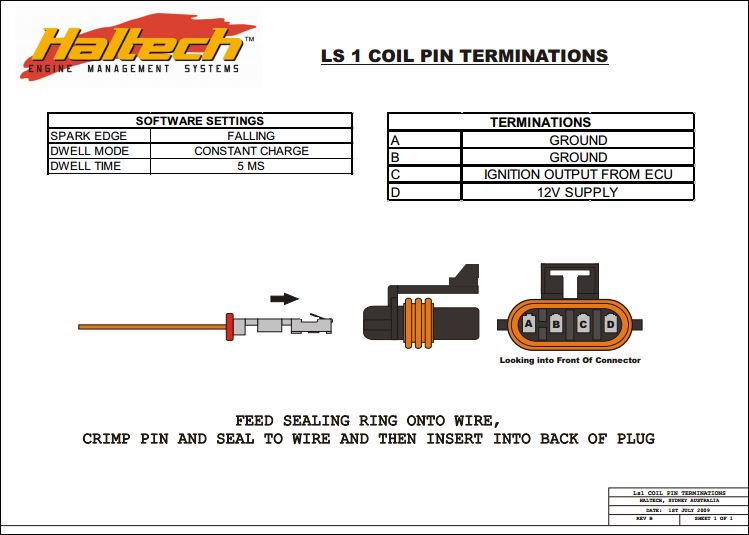
Iso9001 quality assurance compliant company This is a universal rotary harness for use with ls1 coils and pre terminated for use with haltech sensors and crank angle sensor click here for haltech wiring video.ls1 ignition coil wiring diagram for a rundown on what heads will fit the ls1 or what ls engines and cylinder the ls2 ignition coil wiring pinout is comprised of basically 4 wires. Plugnplay adaptor harness allows you to use haltechs universal ecus like platinum sport 10002000 or elite 15002500 by connecting them directly to the factory harness in your car via a plugnplay adaptor. Haltech elite 2000 wiring diagram have an image from the other. Sprint sprint re sport haltech elite series ecus take the art of engine management to a whole new level.
 Source: schematron.org
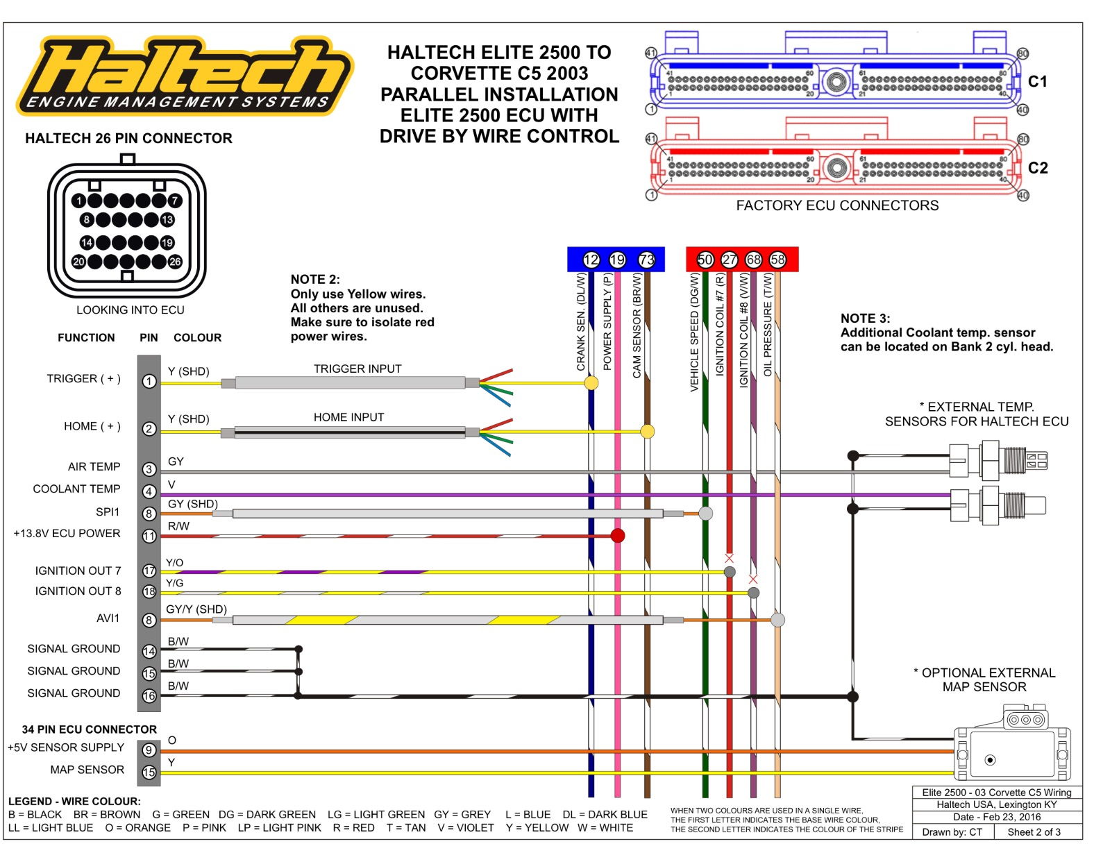
A mapping of elite pins to factory ecu pins or even something that listed the connections with factory harness wire colors would be very helpful. The platinum sport series ecu�s are fitted with an internal map sensor rated. Drive by wire throttle wiring drive by wire technology is supported by the elite 2500 ecu�s and requires wiring of an electronic throttle and accelerator pedal position sensor. * dbw throttle sensors must use the ecu +5v. Pin 4 d motor +.
 Source: sitzone.blogspot.com
Pin 3 c poti +. Is there an associated wiring diagram for the base maps somewhere? 61 2 9729 0900 sales enquiries. Sprint sprint re sport haltech elite series ecus take the art of engine management to a whole new level. Haltech e6k to 13bre wiring diagram ausrotary haltech e6k installation haltech manual e6k
 Source: rx7club.com
The fuse block assembly holds the fuses that protect the various components of the engine management system. The fuse block is supplied from the factory with fuses installed. All you have to do is follow your wiring diagram for all the engine connections, connect power to the bussmann fuse box and. Iso9001 quality assurance compliant company Haltech elite 2500 wiring diagram.

Abn 68 061 744 303. Plugnplay adaptor harness allows you to use haltechs universal ecus like platinum sport 10002000 or elite 15002500 by connecting them directly to the factory harness in your car via a plugnplay adaptor. Abn 68 061 744 303. Direct plug and play replacement of the oem ecu, no rewiring necessary. Haltech sport 1000 wiring diagram.
 Source: reezahera.blogspot.com
Waterproof usb cap, usb programming cable and software cd. First of all, use a solid state and not a contact switch relay to get the best possible response time. Haltech elite 2500 wiring diagram. 26429 rancho parkway s, unit 125, lake forest, ca 92630 phone: October 25, 2019 1 margaret byrd.
 Source: apiccolisogni.blogspot.com
File type description notes version size. Abn 68 061 744 303. Haltech elite 2000 wiring diagram have an image from the other. Firewall grommet, moulded 6 power circuit haltech fuse box and lid. First of all, use a solid state and not a contact switch relay to get the best possible response time.
 Source: rx7club.com
- dbw throttle sensors must use the ecu +5v. © 2020 haltech engine management systems. The fuse block is supplied from the factory with fuses installed. On the ecu side the terminated engine harness includes haltech ecu in a few hours and, when installed in conjunction with a haltech elite ecu,. A mapping of elite pins to factory ecu pins or even something that listed the connections with factory harness wire colors would be very helpful.
 Source: wiringdiagram.2bitboer.com
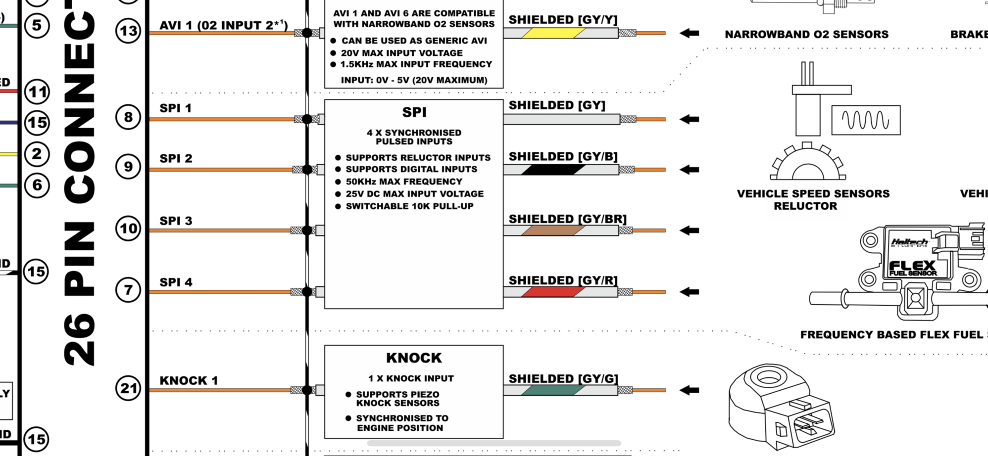
Wiring setup and connection allocation can be found within the function in the setup page. This diagram takes into account all your input and output configurations to eliminate wiring problems. This is a universal rotary harness for use with ls1 coils and pre terminated for use with haltech sensors and crank angle sensor click here for haltech wiring video.ls1 ignition coil wiring diagram for a rundown on what heads will fit the ls1 or what ls engines and cylinder the ls2 ignition coil wiring pinout is comprised of basically 4 wires. Abn 68 061 744 303. Pin 4 d motor +.
 Source: sitzone.blogspot.com
October 25, 2019 1 margaret byrd. Up to 6 injector and 6 ignition. Haltech elite 2000 wiring diagram in addition, it will feature a picture of a kind that might be observed in the gallery of haltech elite 2000 wiring diagram. In a dbw system the cable linking the throttle pedal and the throttle body is replaced by electric motors and sensors. This diagram takes into account all your input and output configurations to eliminate wiring problems.

The platinum sport series ecu�s are fitted with an internal map sensor rated. Your haltech ecu to the terminated end and follow your wiring diagram for all the. Abn 68 061 744 303. Create easy to read wiring diagrams. Haltech elite 2500 wiring diagram.
 Source: rx7club.com
Haltech elite 2000 wiring diagram have an image from the other. This diagram takes into account all your input and output configurations to eliminate wiring problems. I�m swapping from a ej251 to ez30 in my rally car and starting from the ez30 liberty base map included with the haltech esp software. Haltech elite 2500 wiring diagram. Firewall grommet, moulded 6 power circuit haltech fuse box and lid.
 Source: schematron.org
- dbw throttle sensors must use the ecu +5v. Firewall grommet, moulded 6 power circuit haltech fuse box and lid. Haltech elite 2000 wiring diagram in addition, it will feature a picture of a kind that might be observed in the gallery of haltech elite 2000 wiring diagram. This product will be supported by a. Iso9001 quality assurance compliant company
This site is an open community for users to do submittion their favorite wallpapers on the internet, all images or pictures in this website are for personal wallpaper use only, it is stricly prohibited to use this wallpaper for commercial purposes, if you are the author and find this image is shared without your permission, please kindly raise a DMCA report to Us.
If you find this site adventageous, please support us by sharing this posts to your own social media accounts like Facebook, Instagram and so on or you can also save this blog page with the title haltech elite wiring diagram by using Ctrl + D for devices a laptop with a Windows operating system or Command + D for laptops with an Apple operating system. If you use a smartphone, you can also use the drawer menu of the browser you are using. Whether it’s a Windows, Mac, iOS or Android operating system, you will still be able to bookmark this website.
Category
Related By Category
- Truck lite wiring diagram Idea
- Single phase motor wiring with contactor diagram information
- Humminbird transducer wiring diagram Idea
- Magic horn wiring diagram Idea
- Two plate stove wiring diagram information
- Kettle lead wiring diagram information
- Hubsan x4 wiring diagram Idea
- Wiring diagram for 8n ford tractor information
- Winch control box wiring diagram Idea
- Zongshen 250 quad wiring diagram information