Haltech 2500 wiring diagram information
Home » Trend » Haltech 2500 wiring diagram information
Your Haltech 2500 wiring diagram images are available. Haltech 2500 wiring diagram are a topic that is being searched for and liked by netizens now. You can Get the Haltech 2500 wiring diagram files here. Download all royalty-free vectors.
If you’re looking for haltech 2500 wiring diagram pictures information connected with to the haltech 2500 wiring diagram interest, you have pay a visit to the right site. Our website always gives you hints for seeking the maximum quality video and image content, please kindly hunt and locate more enlightening video content and graphics that match your interests.
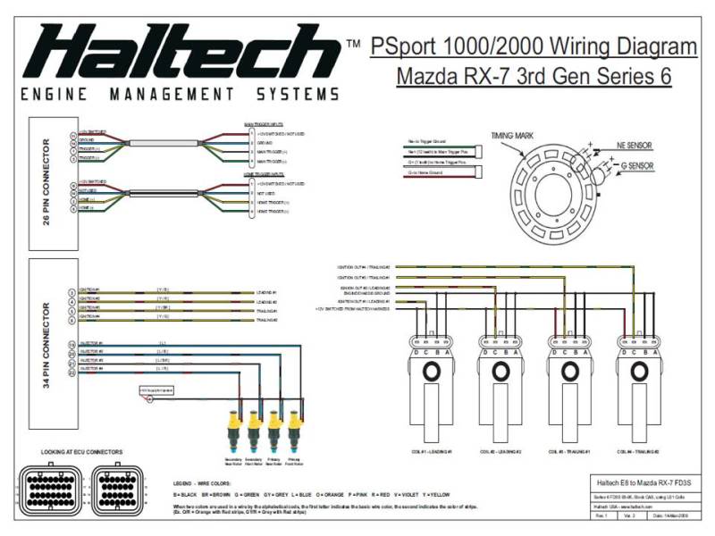
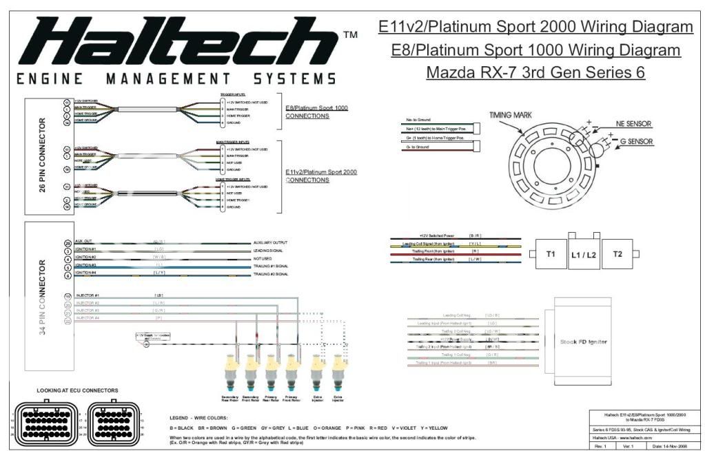
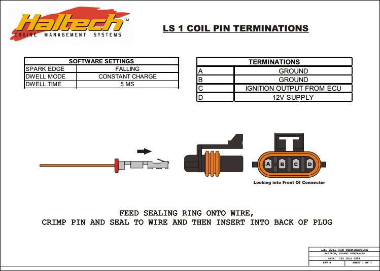
Haltech 2500 Wiring Diagram. Wiring diagram · quick start guide. The fuse block assembly holds the fuses that protect the various components of the engine management system. Waterproof usb cap, usb programming cable and usb All you have to do is follow your wiring diagram for all the engine connections, connect power to the bussmann fuse box and.
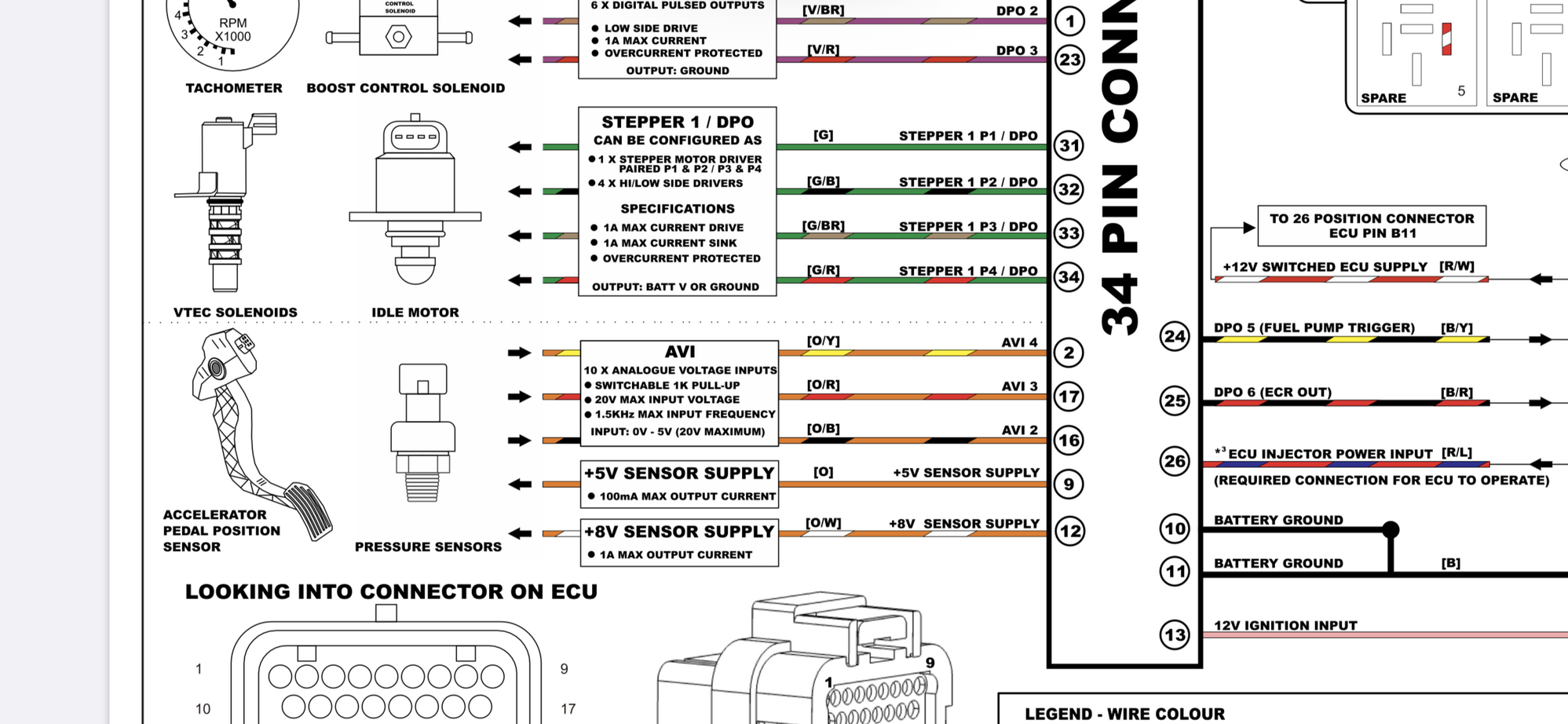 38 Haltech Elite 550 Wiring Diagram Wiring Diagram From sitzone.blogspot.com
First of all, use a solid state and not a contact switch relay to get the best possible response time. Elite 2500 & 2500 t basic universal. Haltech�s elite 2500 ecu takes the art of engine calibration to a whole new level. Elite 2500 wiring diagram b = black br = brown g = green gy = grey l = blue when two colours are used in a wire by the alphabetical code, the second colour indicates the colour of the stripe. Connect your haltech ecu to the terminated end and follow your wiring diagram for. Haltech elite750 transbrake/aux rev limiter wiring diagram help.
Elite 2500 ecu with dbw and race functions.
Bosch dishwasher wiring diagram | my wiring diagram from. Up to 8 injector and 8 ignition. Featuring a robust environmentally sealed waterproof case, drive by wire throttle control, intake and exhaust cam control, short term and long term map learning, dual channel knock control, and much more, the elite 2500 t provides engine calibrators the. All the wires at the unterminated end are colour coded and clearly labelled. Elite 1500/2500 can communications wiring guide. Connect your haltech ecu to the terminated end and follow your wiring diagram for.
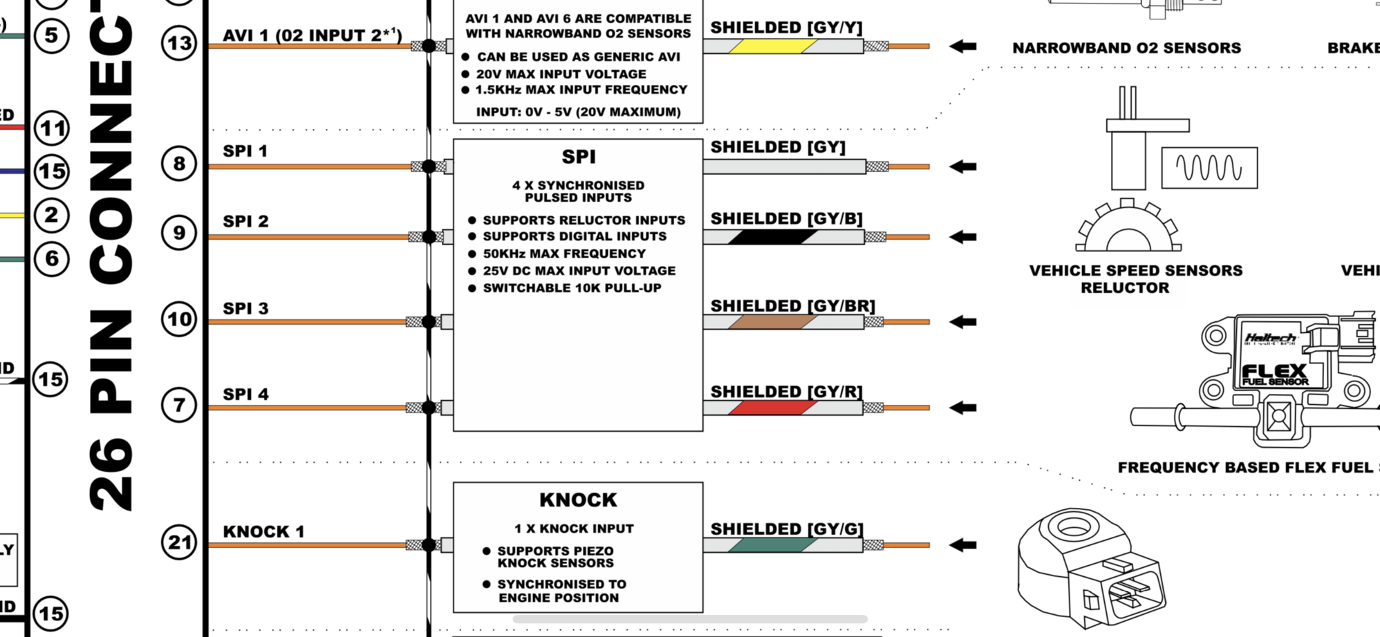 Source: sitzone.blogspot.com
All you have to do is follow your wiring diagram for all the engine connections, connect power to the bussmann fuse box and. Haltech�s elite 2500 ecu takes the art of engine calibration to a whole new level. First of all, use a solid state and not a contact switch relay to get the best possible response time. Haltech�s elite 2500 ecu takes the art of engine calibration to a whole new level. All the wires at the unterminated end are colour coded and clearly labelled.
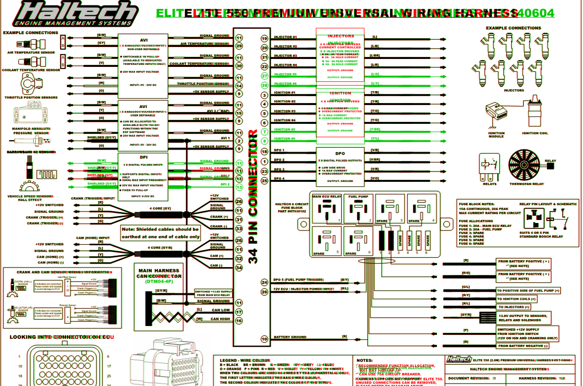 Source: reverseitwell.blogspot.com
All the wires at the unterminated end are colour coded and clearly labelled. Waterproof usb cap, usb programming cable and usb Up to 8 injector and 8 ignition. Haltech elite 2500 wiring diagram. Connect your haltech ecu to the terminated end and follow your wiring diagram for all the engine connections.

The fuse block is supplied from the factory with fuses installed. The wiring diagram is accompanied by the full ecu manual and software located on the cd or usb key provided with the ecu to refer to while completing your installation and configuration. Cimg7.ibsrv.net to attract a cable, merely click the draw lines alternative on the left hand side of the attracting location. Ignition module haltech hpi injectors elite 1500 wiring diagram 34 p in c on ne ct or (a) suits 4 or 5 pin relay pin layout & schematic boost control ignit er nt hp8 +12v switched ecu supply[r/w] fuse block notes: And use 5 volts and grounds for switching on/off.

Featuring a robust environmentally sealed waterproof case, drive by wire throttle control, intake and exhaust cam control, short term and long term map learning, dual channel knock control, and much more, the elite 2500 t provides engine calibrators the. Wiring setup and connection allocation can be found within the function in the setup page. Featuring a robust environmentally sealed waterproof case, drive by wire throttle control, intake and exhaust cam control, short term and long term map learning, dual channel knock control, and much more, the elite 2500 t provides engine calibrators the. Connect your haltech ecu to the terminated end and follow your wiring diagram. Elite 2500 wiring diagram b = black br = brown g = green gy = grey l = blue when two colours are used in a wire by the alphabetical code, the second colour indicates the colour of the stripe.
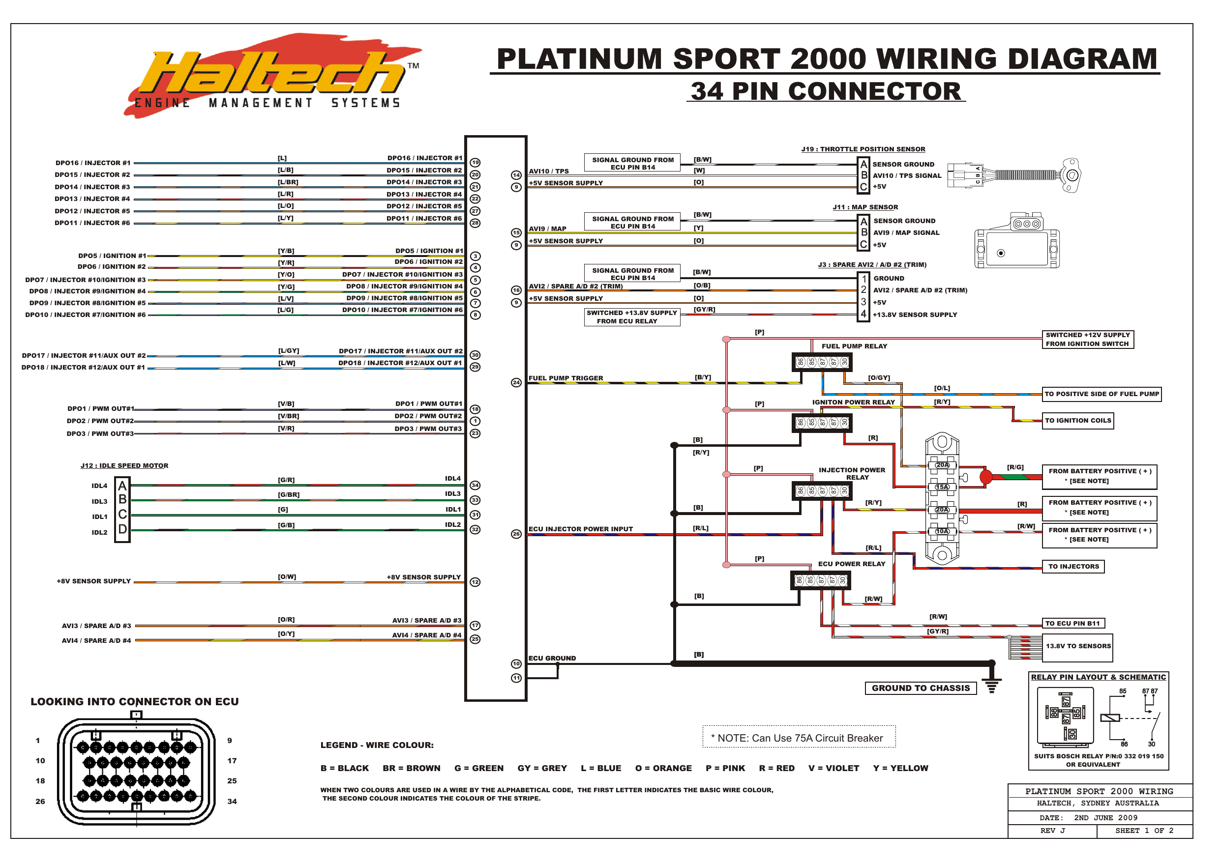 Source: reezahera.blogspot.com
All the wires at the unterminated end are colour coded and clearly labelled. Haltech�s elite 2500 ecu takes the art of engine calibration to a whole new level. Up to 8 injector and 8 ignition. Connect your haltech ecu to the terminated end and follow your wiring diagram for. The fuse ratings and connections are shown in the wiring diagram above, and.
 Source: apiccolisogni.blogspot.com
The fuse ratings and connections are shown in the wiring diagram above, and. Haltech�s elite 2500 ecu takes the art of engine calibration to a whole new level. First of all, use a solid state and not a contact switch relay to get the best possible response time. Elite 2500 wiring diagram b = black br = brown g = green gy = grey l = blue when two colours are used in a wire by the alphabetical code, the second colour indicates the colour of the stripe. Connect your haltech ecu to the terminated end and follow your wiring diagram for all the engine connections.
 Source: sitzone.blogspot.com
Wiring setup and connection allocation can be found within the function in the setup page. Connect your haltech ecu to the terminated end and follow your wiring diagram for all the engine connections. I85.photobucket.com if you need extra symbols, click the arrow beside the visible library to raise a fall menu as well as choose extra. Featuring a robust environmentally sealed waterproof case. The fuse block assembly holds the fuses that protect the various components of the engine management system.

All the wires at the unterminated end are colour coded and clearly labelled. Use launch control and you can set it to activate of the trans brake input, instead of using aux rpm limit. Ignition module haltech hpi injectors [o] 9 +5v sensor supply elite 2500 wiring diagram 34 p in c on ne ct or (a) accelerator pedal position sensor relay pin layout & schematic throttle position sensors manifold absolute pressure sensor haltech boost/fuel/ignition 1 3 2 4 boost control solenoid ignit er ig hp t 8 trim module temperature sensors. Featuring a robust environmentally sealed waterproof case, drive by wire throttle control, intake and exhaust cam control, short term and long term map learning, dual channel knock control, and much more, the elite 2500 ecu provides engine calibrators the tools they need to get the job done right. And use 5 volts and grounds for switching on/off.
 Source: rx7club.com
Haltech�s elite 2500 ecu takes the art of engine calibration to a whole new level. Ignition module haltech hpi injectors [o] 9 +5v sensor supply elite 2500 wiring diagram 34 p in c on ne ct or (a) accelerator pedal position sensor relay pin layout & schematic throttle position sensors manifold absolute pressure sensor haltech boost/fuel/ignition 1 3 2 4 boost control solenoid ignit er ig hp t 8 trim module temperature sensors. 21.02.2019 21.02.2019 7 comments on haltech elite 2500 wiring diagram. Use launch control and you can set it to activate of the trans brake input, instead of using aux rpm limit. Wiring setup and connection allocation can be found within the function in the setup page.
 Source: diagramweb.net
21.02.2019 21.02.2019 7 comments on haltech elite 2500 wiring diagram. Haltech�s elite 2500 ecu takes the art of engine calibration to a whole new level. The wiring diagram is accompanied by the full ecu manual and software located on the cd or usb key provided with the ecu to refer to while completing your installation and configuration. The fuse ratings and connections are shown in the wiring diagram above, and. Drive by wire throttle wiring drive by wire technology is supported by the elite 2500 ecu�s and requires wiring of an electronic throttle and accelerator pedal position sensor.
 Source: sitzone.blogspot.com
Haltech�s elite 2500 ecu takes the art of engine calibration to a whole new level. Featuring a robust environmentally sealed waterproof case, drive by wire throttle control, intake and exhaust cam control, short term and long term map learning, dual channel knock control, and much more, the elite 2500 t provides engine calibrators the. Configure the trans brake function as the input. The fuse block is supplied from the factory with fuses installed. The wiring diagram is accompanied by the full ecu manual and software located on the cd or usb key provided with the ecu to refer to while completing your installation and configuration.
 Source: savingbonsaistarterr.blogspot.com
All you have to do is follow your wiring diagram for all the engine connections, connect power to the bussmann fuse box and. Drive by wire technology is supported by the elite 2500 ecu�s and requires wiring of an electronic throttle and accelerator pedal position sensor. Drive by wire throttle wiring drive by wire technology is supported by the elite 2500 ecu�s and requires wiring of an electronic throttle and accelerator pedal position sensor. All you have to do is follow your wiring diagram for all the engine connections, connect power to the bussmann fuse box and. Ignition module haltech hpi injectors elite 1500 wiring diagram 34 p in c on ne ct or (a) suits 4 or 5 pin relay pin layout & schematic boost control ignit er nt hp8 +12v switched ecu supply[r/w] fuse block notes:
 Source: sitzone.blogspot.com
Connect your haltech ecu to the terminated end and follow your wiring diagram. Ignition module haltech hpi injectors elite 1500 wiring diagram 34 p in c on ne ct or (a) suits 4 or 5 pin relay pin layout & schematic boost control ignit er nt hp8 +12v switched ecu supply[r/w] fuse block notes: The wiring diagram is accompanied by the full ecu manual and software located on the cd or usb key provided with the ecu to refer to while completing your installation and configuration. Fully programmable systems allow you to extract all the performance from your engine. All you have to do is follow your wiring diagram for all the engine connections, connect power to the bussmann fuse box and.

Up to 8 injector and 8 ignition. Ignition module haltech hpi injectors elite 1500 wiring diagram 34 p in c on ne ct or (a) suits 4 or 5 pin relay pin layout & schematic boost control ignit er nt hp8 +12v switched ecu supply[r/w] fuse block notes: Bosch dishwasher wiring diagram | my wiring diagram from. Wiring diagram · quick start guide. Featuring a robust environmentally sealed waterproof case, drive by wire throttle control, intake and exhaust cam control, short term and long term map learning, dual channel knock control, and much more, the elite 2500 ecu provides engine calibrators the tools they need to get the job done right.
 Source: schematron.org
And use 5 volts and grounds for switching on/off. Elite 2500 & 2500 t basic universal. All you have to do is follow your wiring diagram for all the engine connections, connect power to the bussmann fuse box and. Elite 550/750/950/vms diagrams, elite 1000/2000 diagrams, elite 1500/2500/rem diagrams. Elite 2500 ecu with dbw and race functions, injection molded plastic plug ‘n’ play adaptor harness, m14 x 1.5 […]
 Source: schematron.org
Elite 2500 ecu with dbw and race functions. The fuse ratings and connections are shown in the wiring diagram above, and. Ignition module haltech hpi injectors [o] 9 +5v sensor supply elite 2500 wiring diagram 34 p in c on ne ct or (a) accelerator pedal position sensor relay pin layout & schematic throttle position sensors manifold absolute pressure sensor haltech boost/fuel/ignition 1 3 2 4 boost control solenoid ignit er ig hp t 8 trim module temperature sensors. Featuring a robust environmentally sealed waterproof case. All you have to do is follow your wiring diagram for all the engine connections, connect power to the bussmann fuse box and.
 Source: schematron.org
All you have to do is follow your wiring diagram for all the engine connections, connect power to the bussmann fuse box and. Elite 1500/2500 can communications wiring guide. This harness when installed in conjunction with a haltech elite ecu opens the door to virtually limitless performance modification and tuning of your vehicle. Featuring a robust environmentally sealed waterproof case, drive by wire throttle control, intake and exhaust cam control, short term and long term map learning, dual channel knock control, and much more, the elite 2500 ecu provides engine calibrators the tools they need to get the job done right. Connect your haltech ecu to the terminated end and follow your wiring diagram for.
 Source: wiringdiagram.2bitboer.com
Configure the trans brake function as the input. Haltech�s elite 2500 ecu takes the art of engine calibration to a whole new level. Haltech elite750 transbrake/aux rev limiter wiring diagram help. All you have to do is follow your wiring diagram for all the engine connections, connect power to the bussmann fuse box and. The fuse ratings and connections are shown in the wiring diagram above, and.
This site is an open community for users to submit their favorite wallpapers on the internet, all images or pictures in this website are for personal wallpaper use only, it is stricly prohibited to use this wallpaper for commercial purposes, if you are the author and find this image is shared without your permission, please kindly raise a DMCA report to Us.
If you find this site adventageous, please support us by sharing this posts to your preference social media accounts like Facebook, Instagram and so on or you can also save this blog page with the title haltech 2500 wiring diagram by using Ctrl + D for devices a laptop with a Windows operating system or Command + D for laptops with an Apple operating system. If you use a smartphone, you can also use the drawer menu of the browser you are using. Whether it’s a Windows, Mac, iOS or Android operating system, you will still be able to bookmark this website.
Category
Related By Category
- Predator 670 engine wiring diagram Idea
- Frsky x8r wiring diagram information
- Pioneer ts wx130da wiring diagram Idea
- Johnson 50 hp wiring diagram Idea
- Kohler voltage regulator wiring diagram Idea
- Johnson 50 hp outboard wiring diagram information
- Kti hydraulic remote wiring diagram Idea
- Pyle plpw12d wiring diagram information
- Tx9600ts wiring diagram information
- Lifan 50cc wiring diagram information