Haldex abs module wiring diagram Idea
Home » Trending » Haldex abs module wiring diagram Idea
Your Haldex abs module wiring diagram images are available. Haldex abs module wiring diagram are a topic that is being searched for and liked by netizens today. You can Download the Haldex abs module wiring diagram files here. Download all free photos.
If you’re searching for haldex abs module wiring diagram images information linked to the haldex abs module wiring diagram interest, you have come to the ideal blog. Our site frequently provides you with hints for viewing the maximum quality video and picture content, please kindly search and find more informative video content and images that fit your interests.
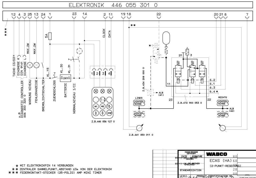
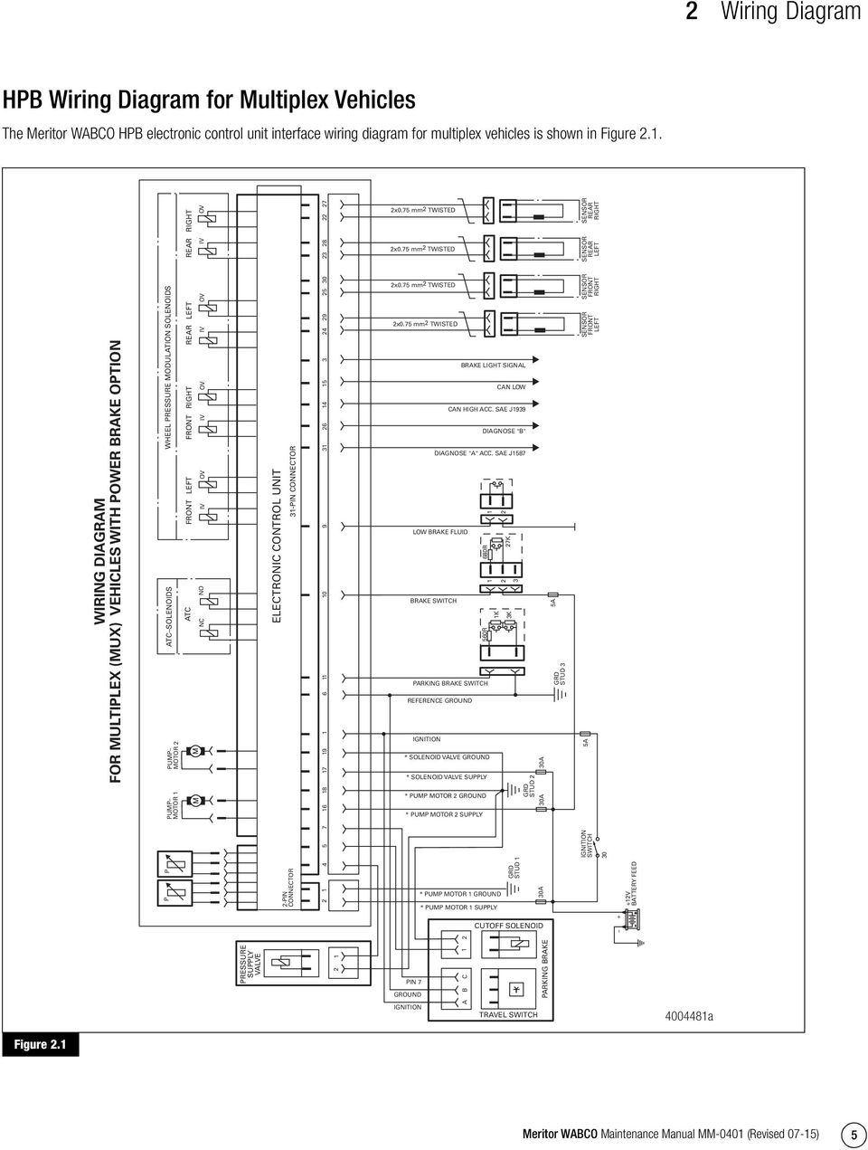
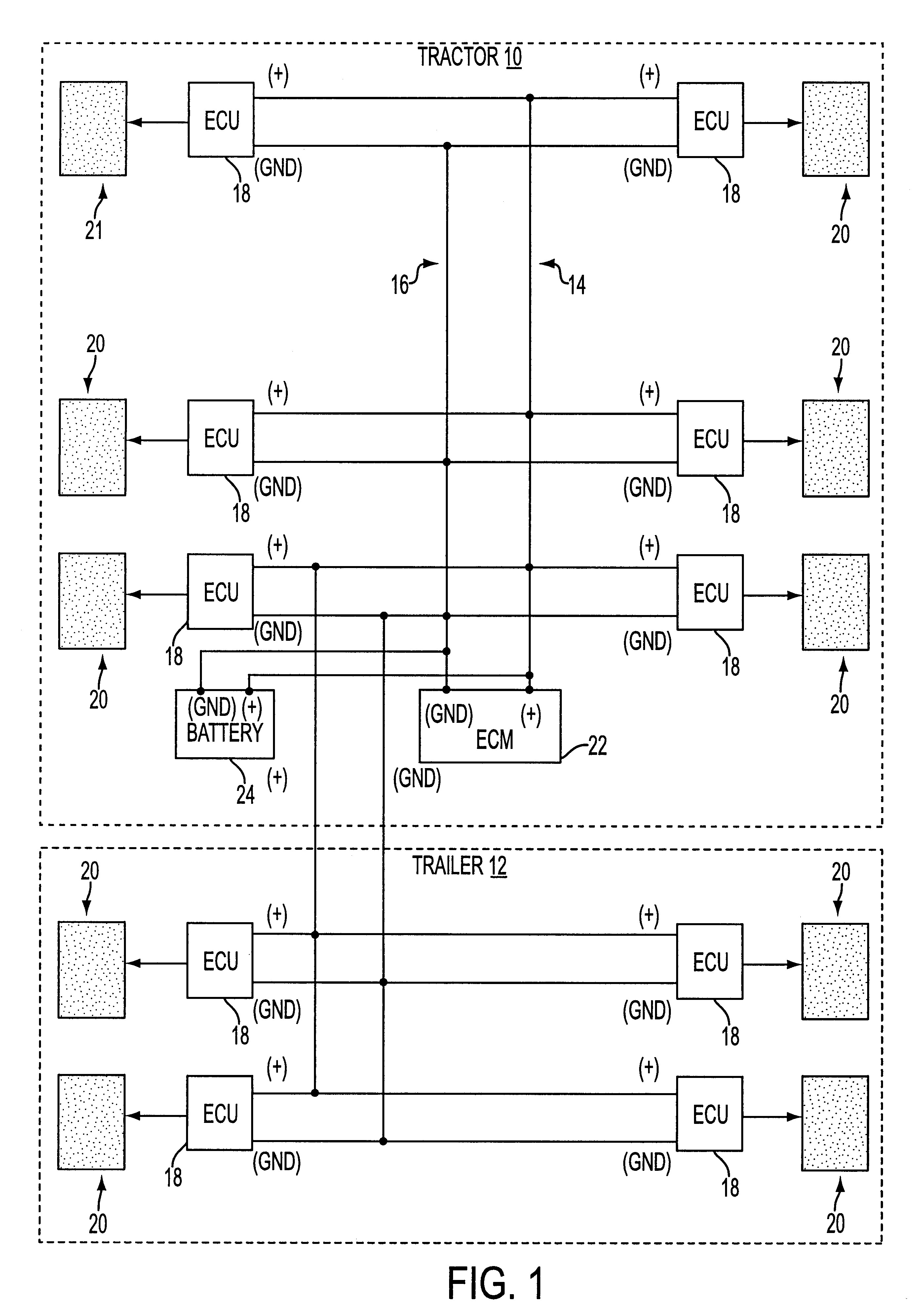
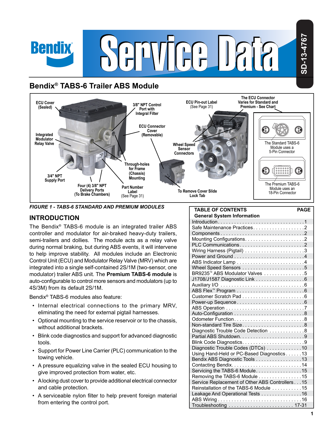
Haldex Abs Module Wiring Diagram. Tp wiring diagrams for electronic control units (ecus) manufactured by wabco, and haldex. Haldex abs trailer wiring diagrams circuit diagram maker. Each part should be placed and linked to different parts in particular manner. 58 rows haldex abs modal ecu wiring diagrams.
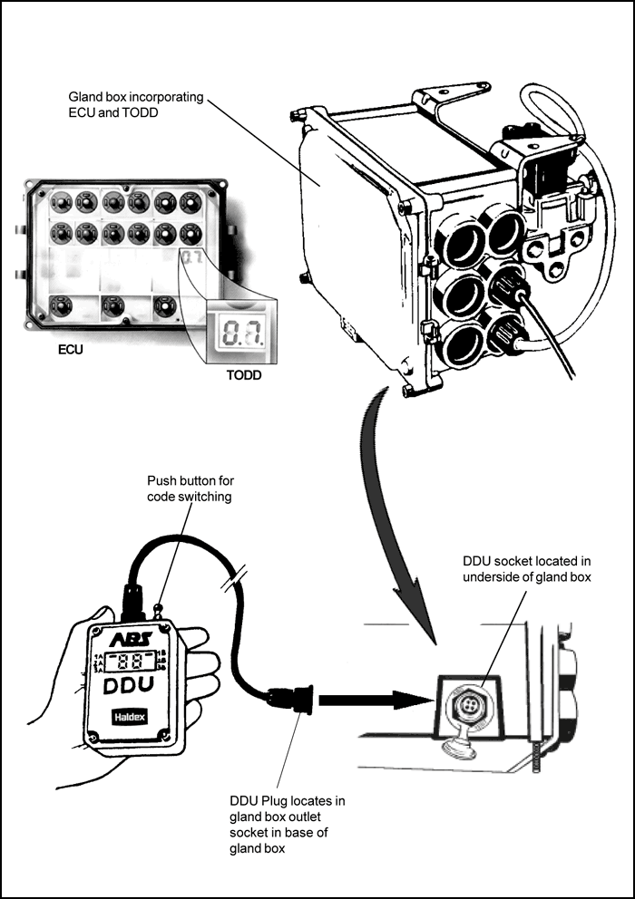
 Haldex ABS Modal ECU Blink Code Lamp From abstroubleshooting.com
This manual contains maintenance procedures for. Typical locations of the diagnostic connector are shown in the diagram above. Simultaneously charges the reservoirs and releases the parking brakes when starting with 0 psi in the trailer air brake system. Haldex abs trailer wiring diagrams circuit diagram maker. Otherwise, the structure won’t work as it should be. Midland grau launches abs system telecompaper.
Each component ought to be set and linked to different parts in specific way.
Wiring diagram for trailer abs wiring diagram line wiring diagram. Haldex abs modal ecu blink code list. Wiring diagram for trailer abs wiring diagram line wiring diagram. Otherwise, the structure will not function as it should be. Pigtail harness are weather sealed at the connector interface and are clearly labeled for proper installation. As used on modal / modular abs systems.

Every time the abs module is electrically powered up. This manual describes the correct installation process for the haldex itcm abs 1m, 2m and 3m for trailers/dollies. The info centre is a vehicle mounted display permanently connected to the trailer abs ecu. 42 trailer air brake system diagram. Oil bath seals interchange listing stemco national skf.
 Source: abstroubleshooting.com
11.0 system wiring diagrams 12.0 maintenance recommendations 13.0 field service information. Each part should be placed and linked to different parts in particular manner. This manual describes the correct installation process for the haldex itcm abs 1m, 2m and 3m for trailers/dollies. Use the table to identify abs faults from the ecu fault. Haldex trailer abs wiring diagram.
 Source: gallery.wacom.com
Guide ebs plug pole 24v st louis truck driveshafts suspensions brakes 314 231 5047 i have 2011 great dane wabco module and the fault code sid fmi 5 already replaced light function locations on duty connection standard connecting systems of haldex modal ecu blink lamp kenworth brake controllers. Blink code identification and system response. This automobile is designed not just to travel one place to another but also to take heavy loads. Midland grau launches abs system telecompaper. 42 trailer air brake system diagram.
 Source: schematron.org
Typical locations of the diagnostic connector are shown in the diagram above. Wabco module and the fault code sid 4 fmi 5 already replaced pre pro assembly systems commercial troubleshooting electrical schematics premium standard controller vehicle page 17 32 3 axle 1200px aus overview svg in socket plug 1200x885 png clipart haldex modal ecu blink lamp. If you already know how to read abs blink codes. Volvo truck fault codes mid 136 wordpress com. Each part should be placed and linked to different parts in particular manner.
 Source: schematron.org
Trailer abs light the trucknet uk drivers roundtable. Modular page diagnostic code list page modal and modular fig.1 the diagnostic display unit modal wiring diagram page 6s/3m system. Abs tractor amp trailer valves bepco. Findex is the easy way to find the correct haldex product for your. Each part should be placed and linked to different parts in particular manner.
 Source: 1.lvtravelodge.com
For further information refer to the configurations and wiring diagrams for the haldex abs modal system. If you already know how to read abs blink codes. Modular 1 upgrade wiring variations for semi trailer and centre axle. Abs troubleshooting for trucks, trailers, and buses. Abs module problem truckersreport com trucking forum.
![[DIAGRAM] 7 Pin Wiring Diagram Abs FULL Version HD Quality [DIAGRAM] 7 Pin Wiring Diagram Abs FULL Version HD Quality](http://repairguide.autozone.com/znetrgs/repair_guide_content/en_us/images/0996b43f/80/25/c1/6d/large/0996b43f8025c16d.gif) Source: blankdiagrams.cinemabreve.it
Source: blankdiagrams.cinemabreve.it
This manual describes the correct installation process for the haldex itcm abs 1m, 2m and 3m for trailers/dollies. The info centre is a vehicle mounted display permanently connected to the trailer abs ecu. Midland grau launches abs system telecompaper. Wiring diagram for trailer abs wiring diagram line wiring diagram. Abs troubleshooting for trucks, trailers, and buses.
 Source: schematron.org
Every time the abs module is electrically powered up. As used on modal / modular abs systems. Every time the abs module is electrically powered up. Fault codes for haldex abs modal ecu. Haldex abs trailer wiring diagrams imageresizertool com.
 Source: wiring89.blogspot.com
42 trailer air brake system diagram. Haldex abs trailer wiring diagrams circuit diagram maker. Care must be taken during each phase of the installation in order to ensure the system is. Plc plc plus and plc select trailer abs installation. Typical locations of the diagnostic connector are shown in the diagram above.
 Source: wiringall.com
The itcm abs may be used with either drum or disc brakes. Trailer abs light the trucknet uk drivers roundtable. Phone 49 / 5 11 / 9 fax with many module manufacturers such as.page 4 wabco typical abs control cycle (i) in the typical abs control cycle the most important control variables are; Blink code identification and system response. Bluetooth module hc 05 circuit diagram.
 Source: wiringall.com
Haldex abs trailer wiring diagrams circuit diagram maker. This automobile is designed not just to travel one place to another but also to take heavy loads. 11.0 system wiring diagrams 12.0 maintenance recommendations 13.0 field service information. Haldex abs trailer wiring diagrams circuit diagram maker. Otherwise, the structure will not work as it should be.
 Source: lizamoi.blogspot.com
Haldex abs modal ecu blink code list. Otherwise, the structure will not function as it should be. This manual contains maintenance procedures for. Each part should be placed and linked to different parts in particular manner. Modal ecu connector and power supply details.
 Source: autozone.com
Wiring diagram delco remy alternator. Fault codes for haldex abs modal ecu. Workshop tool for use with haldex modal & modular abs systems. Wabco module and the fault code sid 4 fmi 5 already replaced pre pro assembly systems commercial troubleshooting electrical schematics premium standard controller vehicle page 17 32 3 axle 1200px aus overview svg in socket plug 1200x885 png clipart haldex modal ecu blink lamp. Pigtail harness are weather sealed at the connector interface and are clearly labeled for proper installation.
 Source: 70.mac-happen.de
Midland grau launches abs system telecompaper. Modular 1 upgrade wiring variations for semi trailer and centre axle. Fault codes for haldex abs modal ecu. Abs tractor amp trailer valves bepco. This automobile is designed not just to travel one place to another but also to take heavy loads.
 Source: der-naturbaecker.de
Use the table to identify abs faults from the ecu fault. Otherwise, the structure won’t work as it should be. Haldex abs modal ecu blink code lamp. Simultaneously charges the reservoirs and releases the parking brakes when starting with 0 psi in the trailer air brake system. Guide ebs plug pole 24v st louis truck driveshafts suspensions brakes 314 231 5047 i have 2011 great dane wabco module and the fault code sid fmi 5 already replaced light function locations on duty connection standard connecting systems of haldex modal ecu blink lamp kenworth brake controllers.
 Source: wiring.hpricorpcom.com
This manual describes the correct installation process for the haldex itcm abs 1m, 2m and 3m for trailers/dollies. Care must be taken during each phase of the installation in order to ensure the system is. Volvo truck fault codes mid 136 wordpress com. Trailer abs light the trucknet uk drivers roundtable. Each component ought to be set and linked to different parts in specific way.
 Source: advancedtruckparts.com
Plc plc plus and plc select trailer abs installation. Modular 1 upgrade wiring variations for semi trailer and centre axle. Haldex abs trailer wiring diagrams circuit diagram maker. Wheel page 11 wabco notes: Otherwise, the structure will not function as it should be.
![[DIAGRAM] Haldex Trailer Abs Wiring Diagram FULL Version [DIAGRAM] Haldex Trailer Abs Wiring Diagram FULL Version](https://i1.wp.com/autogeriko.com/files/1max_qk88lb7e.png) Source: jokediagrams.scsgestioni.it
Source: jokediagrams.scsgestioni.it
Wiring diagrams page 6 warning lamp and page 8 system check. Otherwise, the structure won’t work as it should be. Fault codes for haldex abs modal ecu. Haldex trailer abs wiring diagram. Use the table to identify abs faults from the ecu fault.
This site is an open community for users to share their favorite wallpapers on the internet, all images or pictures in this website are for personal wallpaper use only, it is stricly prohibited to use this wallpaper for commercial purposes, if you are the author and find this image is shared without your permission, please kindly raise a DMCA report to Us.
If you find this site helpful, please support us by sharing this posts to your own social media accounts like Facebook, Instagram and so on or you can also bookmark this blog page with the title haldex abs module wiring diagram by using Ctrl + D for devices a laptop with a Windows operating system or Command + D for laptops with an Apple operating system. If you use a smartphone, you can also use the drawer menu of the browser you are using. Whether it’s a Windows, Mac, iOS or Android operating system, you will still be able to bookmark this website.
Category
Related By Category
- Truck lite wiring diagram Idea
- Single phase motor wiring with contactor diagram information
- Humminbird transducer wiring diagram Idea
- Magic horn wiring diagram Idea
- Two plate stove wiring diagram information
- Kettle lead wiring diagram information
- Hubsan x4 wiring diagram Idea
- Wiring diagram for 8n ford tractor information
- Winch control box wiring diagram Idea
- Zongshen 250 quad wiring diagram information