Gvd 5 wiring diagram Idea
Home » Trending » Gvd 5 wiring diagram Idea
Your Gvd 5 wiring diagram images are available. Gvd 5 wiring diagram are a topic that is being searched for and liked by netizens today. You can Find and Download the Gvd 5 wiring diagram files here. Download all free photos.
If you’re looking for gvd 5 wiring diagram images information related to the gvd 5 wiring diagram interest, you have pay a visit to the ideal site. Our site always provides you with suggestions for viewing the highest quality video and picture content, please kindly search and find more enlightening video content and images that fit your interests.
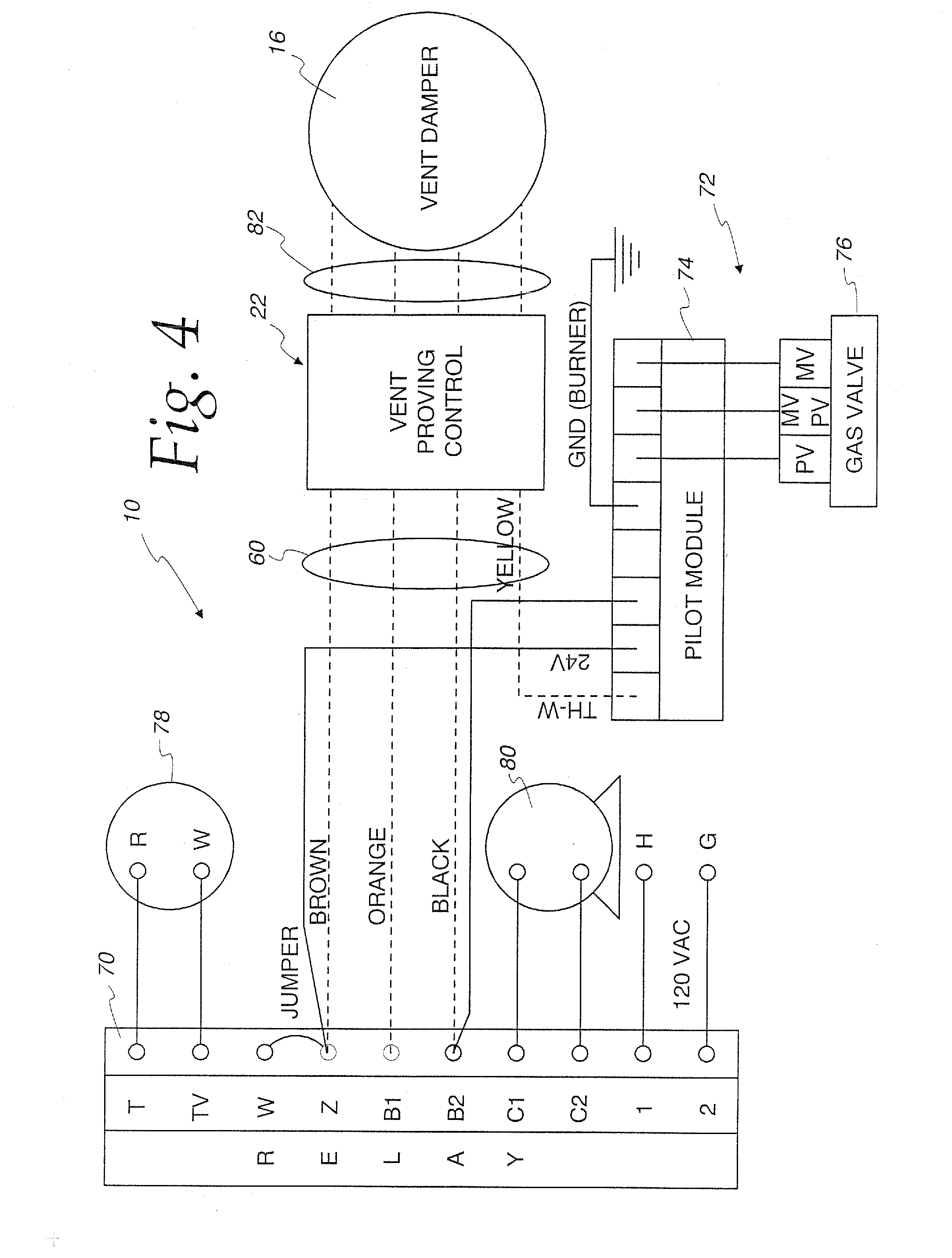
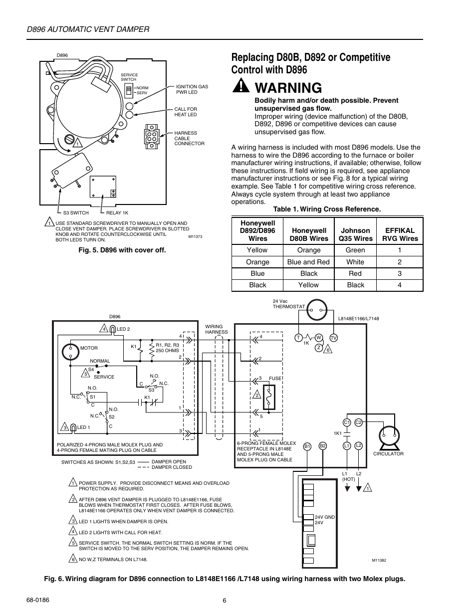
Gvd 5 Wiring Diagram. Wiring l8148e1265 with internal plug directly to vent damper in hydronic intermittent pilot system. Field controls (gvd) gas vent damper was developed to reduce off cycle venting 5. General design and operation the chempump is a combination centrifugal pump and a squirrel cage induction electric motor, built together into a single hermetically sealed unit. The gvd, gas venting damper, will not interfere with existing.
 Gvd6 Wiring Diagram From wiringall.com
Engine wiring84_pmgr isuzu ftr wiring diagram.jpg: An outlet box connector is on each end. The gvd series vent damper must be electrically connected with appliance burner control circuit. Block and wiring diagram dimensions. In most older buildings, the chimneys were designed to pull air through a bed of coal, which takes a lot more draft. Retrofit installations require a wire harne ss.
A typical standing pilot hookup with an added gas valve is shown in diagram a.
Isuzu pickup 4×4 efi fuse box wiring diagram.gif: Be careful not to allow the wire harness to come in contact with hot surfaces. Some oem supplied units have the wiring harness attached. Gvd 6 wiring diagram download honeywell lyric t5 wiring diagram lovely fortable honeywell. 3102 isuzu ftr wiring diagram.gif: Terminals, wire cross section 2,5 mm² flex wire / 4 mm² one wire bolting torque terminals 0,5 nm.
 Source: rachelleogyaz.blogspot.com
Terminals, wire cross section 2,5 mm² flex wire / 4 mm² one wire bolting torque terminals 0,5 nm weight ~ 150 g. Retrofit installations require a wire harness. Keyed wiring harness connector plug installs only one way, preventing incorrect wiring connection. Retrofit installations require a wire harne ss. If the ventilator includes one of these dampers when the fan is started the damper

Field controls gas vent dampers (gvd) are made of stainless steel and is available in 8 sizes, 4″ through 10″ and 12″. Isuzu pickup 4×4 efi fuse box wiring diagram.gif: If the ventilator includes one of these dampers when the fan is started the damper Terminals, wire cross section 2,5 mm² flex wire / 4 mm² one wire bolting torque terminals 0,5 nm. Some oem supplied units have the wiring harness attached.
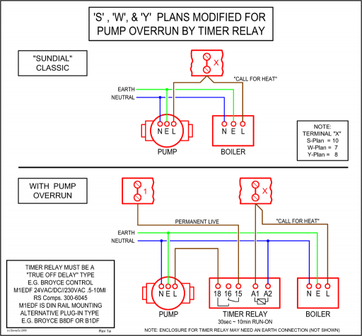 Source: wiringall.com
Variety of gvd 6 wiring diagram. If the ventilator includes one of these dampers when the fan is started the damper Inspect for damage prior to the installation. Inspect for damage prior to the installation. Engine wiring84_pmgr isuzu ftr wiring diagram.jpg:
![[DIAGRAM] Champion Boat Wiring Diagram Engine [DIAGRAM] Champion Boat Wiring Diagram Engine](https://ezgiresortotel.netlify.app/img/placeholder.svg)
Some oem supplied units have the wiring harness attached. Inspect for damage prior to the installation. Wiring l8148e1265 with internal plug directly to vent damper in hydronic intermittent pilot system. @pmj has a good point. The gvd, gas venting damper, will not interfere with existing.

The field vent damper is installed in the vent pipe, after the draft hood, or barometric. Engine wiring84_pmgr isuzu ftr wiring diagram.jpg: Dual safety switches allow the burner to fire only when the damper is in the open position. @pmj has a good point. Keeps cold air out, warm air in.
 Source: customer.honeywell.com
Field controls 46579100 gvd gas vent damper universal wiring kit 8� leads includes adapters. In most older buildings, the chimneys were designed to pull air through a bed of coal, which takes a lot more draft. General design and operation the chempump is a combination centrifugal pump and a squirrel cage induction electric motor, built together into a single hermetically sealed unit. The field controls gvd series gas vent damper is packaged in a single carton containing an assembled gvd, instruction manual and a plug. Keyed wiring harness connector plug installs only one way, preventing incorrect wiring connection.
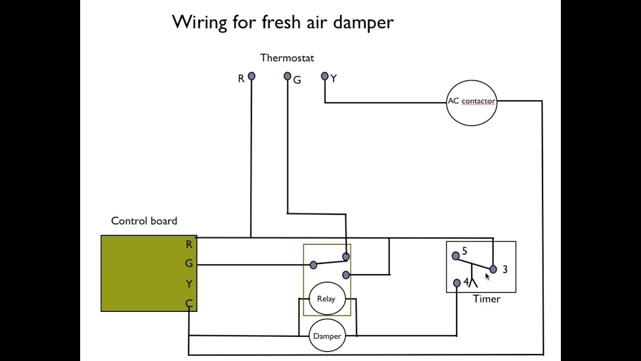 Source: schematron.org
Inspect for damage prior to the installation. Inspect for damage prior to the installation. 1.5 operating instructions 1.5.1 scope these operating instructions apply for all condensers of the series gvd. Order the universal wire harness #46390008. The wire harness shall be securely fastened thru the conduit bracket, located on the vent damper motor assembly.

2.2 warning signs and their meaning in this operation instructions warns against harm to health contact with or inhaling harmful to health or irritant substances can An outlet box connector is on each end. Some oem supplied units have the wiring harness attached. Some oem supplied units have the wiring harness attached. Ships from and sold by prosupplydirect.
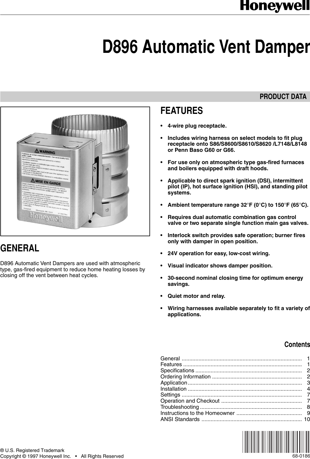 Source: usermanual.wiki
Retrofit installations require a wire harness. The field controls gvd series gas vent damper is packaged in a single carton containing an assembled gvd, instruction manual, and a plug. Wiring l8148e1265 with internal plug directly to vent damper in hydronic intermittent pilot system. Field controls 46579100 gvd gas vent damper universal wiring kit 8� leads includes adapters. Inspect for damage prior to the installation.
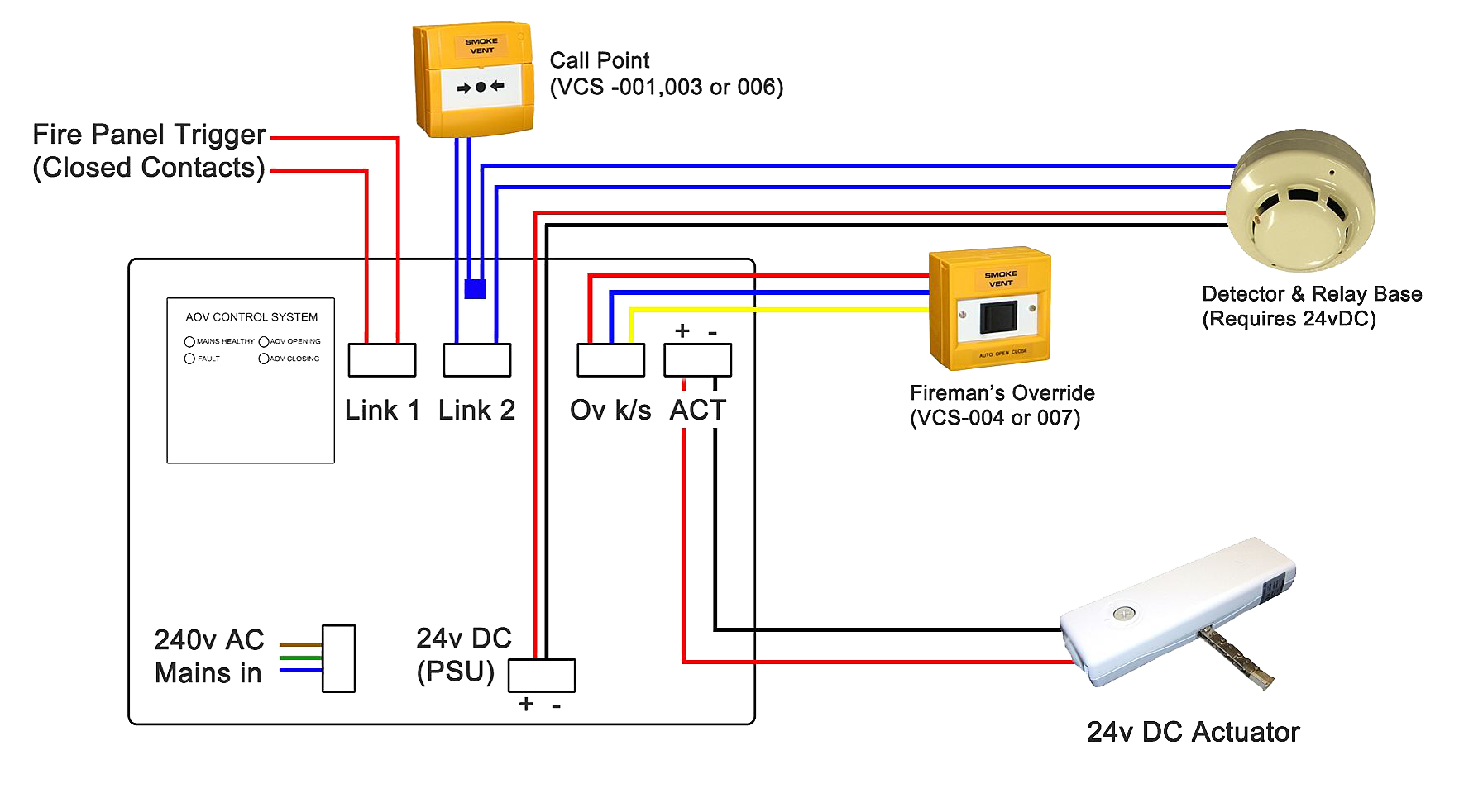 Source: wiring88.blogspot.com
Order the universal wire harness #46390008. Some oem supplied units have the wiring harness attached. The field controls gvd series gas vent damper is packaged in a single carton containing an assembled gvd, instruction manual, and a plug. Don�t forget, if the damper is a field or effikal, you can replace just the motor assembly which includes the safety interlocks. The wire harness shall be securely fastened thru the conduit bracket, located on the vent damper motor assembly.
 Source: wiringall.com
Be careful not to allow the wire harness to come in contact with hot surfaces. Field controls 46579100 gvd gas vent damper universal wiring kit 8� leads includes adapters. Keyed wiring harness connector plug installs only one way, preventing incorrect wiring connection. The gvd series vent damper must be electrically connected with appliance burner control circuit. Isuzu pickup 4×4 efi fuse box wiring diagram.gif:

Installation manual and wiring diagram for fsm low profile series millivolt fireplace damper. Map_sensor_wire_diagram%202 isuzu ftr wiring diagram.jpg: The field controls gvd series gas vent damper is packaged in a single carton containing an assembled gvd, instruction manual and a plug. Some oem supplied units have the wiring harness attached. Field controls gas vent dampers (gvd) are made of stainless steel and is available in 8 sizes, 4″ through 10″ and 12″.
 Source: schematron.org
Block and wiring diagram dimensions. The field controls gvd series gas vent damper is packaged in a single carton containing an assembled gvd, instruction manual and a plug. If the ventilator includes one of these dampers when the fan is started the damper An outlet box connector is on each end. Some oem supplied units have the wiring harness attached.
 Source: wiring88.blogspot.com
Isuzu pickup 4×4 efi fuse box wiring diagram.gif: Order the universal wire harness #46390008. A wiring diagram is a streamlined standard photographic representation of an electrical circuit. Inspect for damage prior to the installation. Don�t forget, if the damper is a field or effikal, you can replace just the motor assembly which includes the safety interlocks.
 Source: manualsdir.com
Dual safety switches allow the burner to fire only when the damper is in the open position. Map_sensor_wire_diagram%202 isuzu ftr wiring diagram.jpg: Inspect for damage prior to the installation. This keyed wiring harness connector plug installs only one way, preventing. Dual safety switches allow the burner to fire only when the damper is in the open position.
 Source: customer.honeywell.com
The field vent damper is installed in the vent pipe, after the draft hood, or barometric. Field controls gas vent dampers (gvd) are made of stainless steel and is available in 8 sizes, 4″ through 10″ and 12″. 3102 isuzu ftr wiring diagram.gif: The gvd, gas venting damper, will not interfere with existing. Keeps cold air out, warm air in.
 Source: wiringall.com
Field controls (gvd) gas vent damper was developed to reduce off cycle venting 5. Retrofit installations require a wire harne ss. Terminals, wire cross section 2,5 mm² flex wire / 4 mm² one wire bolting torque terminals 0,5 nm. A wiring diagram is a streamlined standard photographic representation of an electrical circuit. Terminals, wire cross section 2,5 mm² flex wire / 4 mm² one wire bolting torque terminals 0,5 nm weight ~ 150 g.
 Source: wiring88.blogspot.com
The gvd, gas venting damper, will not interfere with existing. Block and wiring diagram dimensions modbus communication In most older buildings, the chimneys were designed to pull air through a bed of coal, which takes a lot more draft. Tt 1 234 5 6 tt 1 234 5 6 tt 1 23 5 6 gl2 l1 t t c1 c2 b2 b1 f f t t l1 (hot) l2 pump pump pump t87f t87f t87f r845 relay r845 r845 c554. Two screws, the wiring harness plug and you�re done.
This site is an open community for users to share their favorite wallpapers on the internet, all images or pictures in this website are for personal wallpaper use only, it is stricly prohibited to use this wallpaper for commercial purposes, if you are the author and find this image is shared without your permission, please kindly raise a DMCA report to Us.
If you find this site convienient, please support us by sharing this posts to your own social media accounts like Facebook, Instagram and so on or you can also save this blog page with the title gvd 5 wiring diagram by using Ctrl + D for devices a laptop with a Windows operating system or Command + D for laptops with an Apple operating system. If you use a smartphone, you can also use the drawer menu of the browser you are using. Whether it’s a Windows, Mac, iOS or Android operating system, you will still be able to bookmark this website.
Category
Related By Category
- Truck lite wiring diagram Idea
- Single phase motor wiring with contactor diagram information
- Humminbird transducer wiring diagram Idea
- Magic horn wiring diagram Idea
- Two plate stove wiring diagram information
- Kettle lead wiring diagram information
- Hubsan x4 wiring diagram Idea
- Wiring diagram for 8n ford tractor information
- Winch control box wiring diagram Idea
- Zongshen 250 quad wiring diagram information