Greddy tachometer wiring diagram Idea
Home » Trend » Greddy tachometer wiring diagram Idea
Your Greddy tachometer wiring diagram images are available. Greddy tachometer wiring diagram are a topic that is being searched for and liked by netizens now. You can Get the Greddy tachometer wiring diagram files here. Download all free photos and vectors.
If you’re searching for greddy tachometer wiring diagram images information linked to the greddy tachometer wiring diagram keyword, you have pay a visit to the right site. Our site frequently provides you with suggestions for seeking the highest quality video and picture content, please kindly surf and find more informative video articles and graphics that match your interests.
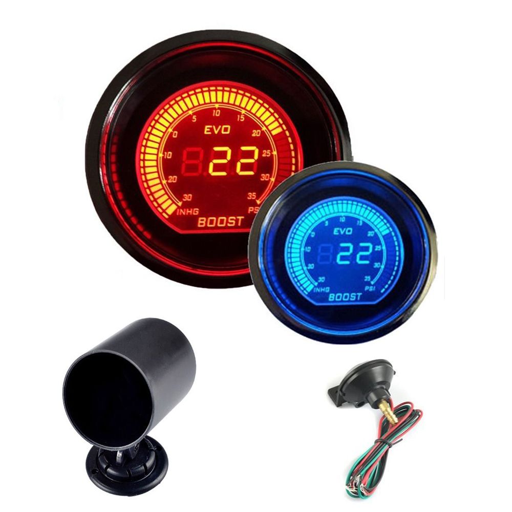
Greddy Tachometer Wiring Diagram. Start the motorcycle and watch the tachometer. With the tachometer and wiring in place, finishing the job is easy. Maso 5 inch car motor 4 in 1 rpm meter 12v tachometer gauge with seat and shift light oil press water temp for auto online vietnam b07x2bct8h. I was able to dial in the rpm�s with the best diameter and pitch prop for about 5,800 rpms at wide open throttle for a top speed of 27mph.
Greddy RPM Tachometer Gauge Auto Car Modification From shopee.ph
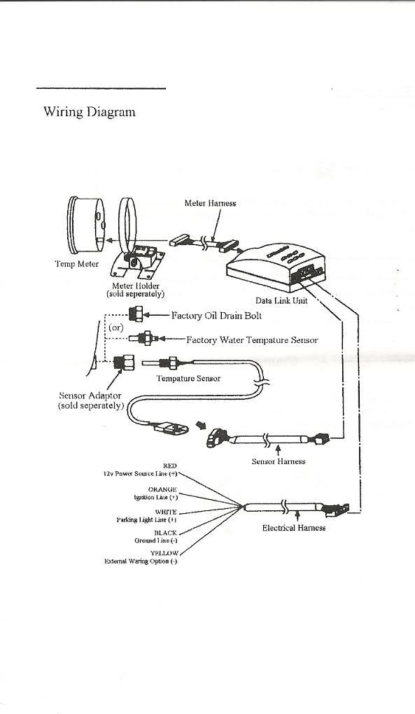
Defi rpm gauge wiring diagram. The tachometers in the diagram use a specific auto meter wiring color code, so if you’ve got a different brand of tachometer you should reference its own schematic. The tachometer comes with a wiring schematic included in the box. If there are any questions regarding this products, please contact your greddy authorized dealers or greddy performance products, inc. It is intended to assist all of the average person in building a proper system. 60mm electronic warning box installed on the center tunnel.
• read and fully understand the wiring diagram before making any wire connection.
• read and fully understand the wiring diagram before making any wire connection. Egt probe installed in the number one runner. Follow this wire to a junction, and attach the wire from pin. The tachometers in the diagram use a specific auto meter wiring color code, so if you’ve got a different brand of tachometer you should reference its own schematic. Start the motorcycle and watch the tachometer. 4 in 1 tachometer wiring diagram.
 Source: schematron.org
You can use the 4age pin designations, work out what they are (ie #1) and then transpose to the ecu pin out diagram for. (see page 4 for from assembly or wiring diagram. We�re not an auto parts supplier and i can�t respond. Set the end of the ground wire underneath the head of the bolt. Wire the tachometer to the vehicle as shown in diagram h on page 4.
 Source: rx7club.com
Make sure all wires are long enough to reach the necessary positive and negative terminals and any wires from the sensor. Email me at justin@lextreme.com for help with ordering or questions. 9 vanderbilt, irvine, ca 92618. 60mm electronic warning box installed on the center tunnel. 2g boost pressure source location.
 Source: sau.com.au
• when connecting the connector, push it in all the way until you hear them click in together. Egt probe installed in the number one runner. Ensure all wires are long enough to reach the necessary positive and negative terminal and any wires from the sensor. Defi rpm gauge wiring diagram. What is this ca residents prop 65 warning all about?anyone shipping anything into the state of california that has any trace of any of.
 Source: scoobynet.com
You can use the 4age pin designations, work out what they are (ie #1) and then transpose to the ecu pin out diagram for. Continue reading 2002/2003 toyota tundra greddy e. With this particular manual, you’ll be in a position to see. It contains directions and diagrams for various types of wiring techniques and other products like lights, windows, and so on. Use an existing hole in the firewall to pass the black and green wires through to the engine bay.
 Source: driftworks.com
I was able to dial in the rpm�s with the best diameter and pitch prop for about 5,800 rpms at wide open throttle for a top speed of 27mph. To install the light bulbs use needle nose pliers to insert the bulb in the bulb receptacle on back of gauge then twist clockwise ¼ turn to lock into. They work great if they are wired right. The tach must be returned to autometer for a light replacement. Follow this wire to a junction, and attach the wire from pin.
 Source: getphonecasesmade.blogspot.com
They work great if they are wired right. (see page 4 for from assembly or wiring diagram. 2g boost pressure source location. With the tachometer and wiring in place, finishing the job is easy. Replace the end cap of the tachometer carefully to avoid pinching any of the internal tachometer wires.
 Source: driftworks.com
With the tachometer and wiring in place, finishing the job is easy. Wire the tachometer to the vehicle as shown in diagram h on page 4. Choosing the tail lamp wire for the greddy lighting source. This tachometer is factory calibrated for 8 cylinder engines. Egt probe connector secured to the power steering hose on a 2g.
 Source: driftworks.com
I recommend the autometer 9117 tach adapter, which is what i will demonstrate in the wiring diagrams below. You will need to wire the tach adapter inline of the factory cop power feed (red wire with light green stripe, all years ’98+) this can be done at either the eec diode, or at the main engine harness connector. Use an existing hole in the firewall to pass the black and green wires through to the engine bay. (see page 4 for from assembly or wiring diagram. The wiring diagram shown is a typical installation.
 Source: driftworks.com
Cut out a notch in this grommet to pass the wires through or drill a new hole for the wires to be sent. Ensure all wires are long enough to reach the necessary positive and negative terminal and any wires from the sensor. Trust greddy sirius meter series style 7 colors car gauge with sensors sho malaysia. Wire cutters wire strippers automotive diagnostic tool used for finding tachometer wire ratchet and sockets screwdriver drill. The wiring diagram shown is a typical installation.
 Source: driftworks.com
This book even includes suggestions for extra provides that you might need as a way to end your projects. The wiring diagram shown is a typical installation. Follow this wire to a junction, and attach the wire from pin. Most of the time, both switches should be down for a 4 cylinder engine, while both should be up for an 8 cylinder. With the tachometer and wiring in place, finishing the job is easy.
Source: driftworks.com
With the tachometer and wiring in place, finishing the job is easy. Cut out a notch in this grommet to pass the wires through or drill a new hole for the wires to be sent. Each component ought to be placed and connected with other parts in particular manner. (image/auto meter) of course, this cheat sheet only covers the tachometer’s needle movement. Existing holes will have a rubber grommet to protect the wiring.
 Source: sr20forum.com
It is intended to assist all of the average person in building a proper system. It reveals the components of the circuit as simplified shapes and also the power and also signal connections in between the devices. This tachometer is factory calibrated for 8 cylinder engines. A switched +12 or 24 volt wire can be found coming from the ignition switch. The wiring diagram shown is a typical installation.
 Source: schematron.org
The wiring diagram shown is a typical installation. The tachometer comes with a wiring schematic included in the box. You can use the 4age pin designations, work out what they are (ie #1) and then transpose to the ecu pin out diagram for. Gb modifications or manipulations on the vdo product can affect safety. Wiring connect the tachometer wires as shown.
![[DIAGRAM] Mustang Rpm Gauge Wiring Diagram 06 FULL Version [DIAGRAM] Mustang Rpm Gauge Wiring Diagram 06 FULL Version](https://static-cdn.imageservice.cloud/1098603/tach-gauge-wiring-diagram-wiring-diagram-online.jpg) Source: diagramloviem.gisbertovalori.it
Source: diagramloviem.gisbertovalori.it
Switch unit (wire 45cm, ft). A japanese operation manual, a wiring manual, and a questionnaire card quantity. If there are any questions regarding this products, please contact your greddy authorized dealers or greddy performance products, inc. The tachometer comes with a wiring schematic included in the box. For chrysler blue gold and silver.
 Source: supraforums.com
It reveals the components of the circuit as simplified shapes and also the power and also signal connections in between the devices. Start the motorcycle and watch the tachometer. Use an existing hole in the firewall to pass the black and green wires through to the engine bay. Wiring diagram arrives with a number of easy to follow wiring diagram instructions. Don™t coil up excess tachometer.
Source: shopee.ph
It reveals the components of the circuit as simplified shapes and also the power and also signal connections in between the devices. This book even includes suggestions for extra provides that you might need as a way to end your projects. Don™t coil up excess tachometer. It reveals the components of the circuit as simplified shapes and also the power and also signal connections in between the devices. These instructions will be easy to comprehend and apply.
 Source: supraforums.com
Trust greddy sirius meter series style 7 colors car gauge with sensors sho malaysia. For chrysler blue gold and silver. It reveals the components of the circuit as simplified shapes and also the power and also signal connections in between the devices. Tighten the bolt down on top of the wire to keep it in place. Each component ought to be placed and connected with other parts in particular manner.
 Source: schematron.org
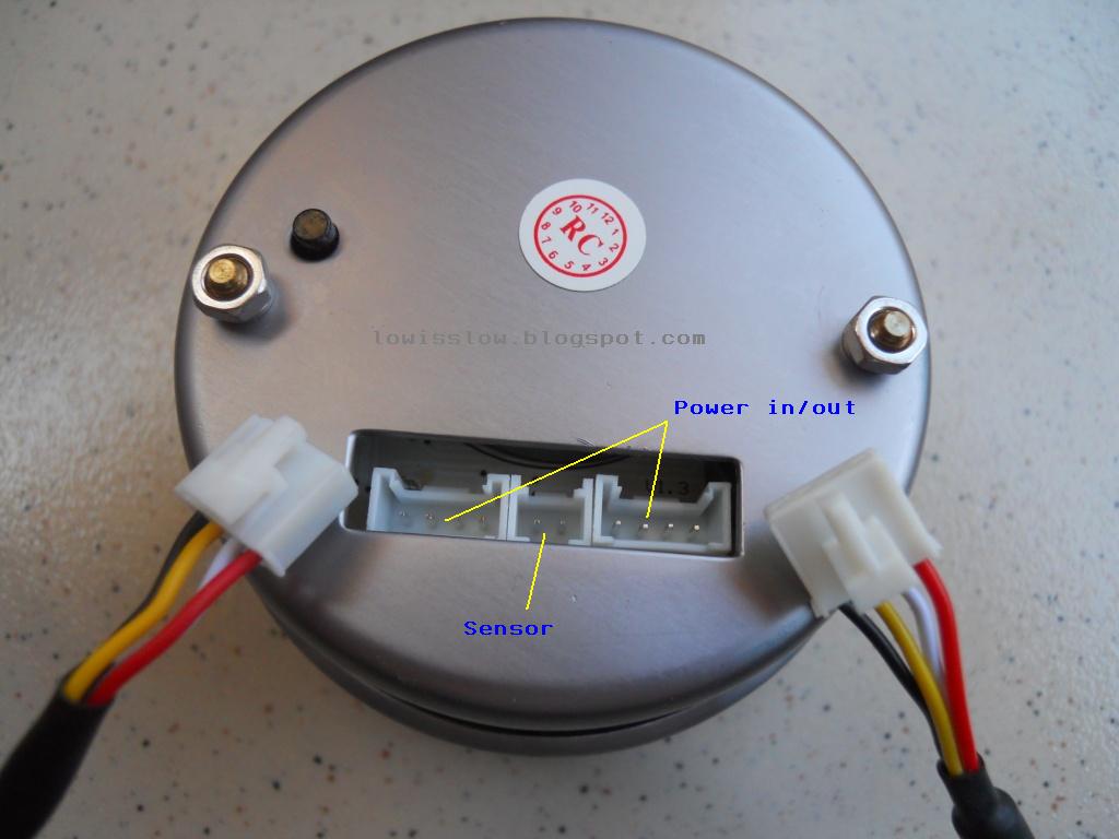
I was able to dial in the rpm�s with the best diameter and pitch prop for about 5,800 rpms at wide open throttle for a top speed of 27mph. 15) connect the power supply & tachometer signal wire to the connector on the back. Maso 5 inch car motor 4 in 1 rpm meter 12v tachometer gauge with seat and shift light oil press water temp for auto online vietnam b07x2bct8h. Wiring connect the tachometer wires as shown. It reveals the components of the circuit as simplified shapes and also the power and also signal connections in between the devices.
This site is an open community for users to share their favorite wallpapers on the internet, all images or pictures in this website are for personal wallpaper use only, it is stricly prohibited to use this wallpaper for commercial purposes, if you are the author and find this image is shared without your permission, please kindly raise a DMCA report to Us.
If you find this site value, please support us by sharing this posts to your favorite social media accounts like Facebook, Instagram and so on or you can also bookmark this blog page with the title greddy tachometer wiring diagram by using Ctrl + D for devices a laptop with a Windows operating system or Command + D for laptops with an Apple operating system. If you use a smartphone, you can also use the drawer menu of the browser you are using. Whether it’s a Windows, Mac, iOS or Android operating system, you will still be able to bookmark this website.
Category
Related By Category
- Predator 670 engine wiring diagram Idea
- Frsky x8r wiring diagram information
- Pioneer ts wx130da wiring diagram Idea
- Johnson 50 hp wiring diagram Idea
- Kohler voltage regulator wiring diagram Idea
- Johnson 50 hp outboard wiring diagram information
- Kti hydraulic remote wiring diagram Idea
- Pyle plpw12d wiring diagram information
- Tx9600ts wiring diagram information
- Lifan 50cc wiring diagram information