Gmos 01 wiring diagram information
Home » Trend » Gmos 01 wiring diagram information
Your Gmos 01 wiring diagram images are available in this site. Gmos 01 wiring diagram are a topic that is being searched for and liked by netizens today. You can Download the Gmos 01 wiring diagram files here. Get all free vectors.
If you’re searching for gmos 01 wiring diagram images information connected with to the gmos 01 wiring diagram interest, you have come to the ideal blog. Our site always provides you with suggestions for viewing the highest quality video and picture content, please kindly surf and find more informative video content and images that fit your interests.
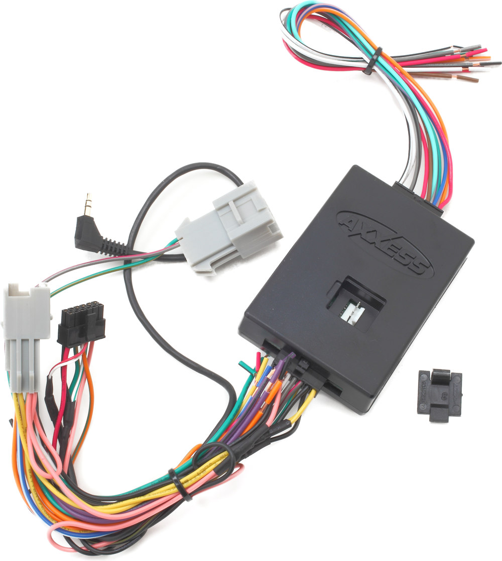
Gmos 01 Wiring Diagram. Gmos lan 01 wiring diagram collection. Axxess gmos lan 01 wiring diagram. Metra gmos onstar interface for gm systems. Cut the gray wire about half way between the two plugs.
 Gmos Lan 01 Wiring Diagram Collection Wiring Collection From headcontrolsystem.com
Gm data interface 2000 2013. For models with nav use the gmos lan 08. The following wires on the 14 pin harness are for the aftermarket radios that have navigation built in: Obtaining from factor a to point b. I have no factory amp but (see wiring diagram on page 6) plug to the negative speaker wire of the metra sp or equivalent. Ca2 metra gmos 04 wiring diagram epanel digital books.
The amplifier, follow the “axxess interface amp bypass schematic” online.
4.1 out of 5 stars. Bose speaker system need wiring diagram please 1999 2013. It reveals the components of the circuit as simplified forms, as well as the power as well as signal links between the tools. This product is temporarily out of stock. Connect the yellow wire to the radio s 12 volt battery or memory wire. Ax adct2 axxess integrate with wiring diagram gansoukin me.
 Source: ricardolevinsmorales.com
(1) these vehicles are standard for a factory amplifier. Cut the gray wire about half way between the two plugs. • connect the blue wire to the antenna turn on wire of the aftermarket radio. Gmos lan 01 wiring diagram collection. Connect the blue/pink wire to the vss or speed sense wire of the aftermarket navigation radio.
 Source: faceitsalon.com
Metra gmos onstar interface for gm systems. It reveals the components of the circuit as simplified forms, as well as the power as well as signal links between the tools. This product is temporarily out of stock. *these vehicles are standard for a factory amplifier. For models with nav use the gmos lan 08.
Source: kibodeclanchester.blogspot.com
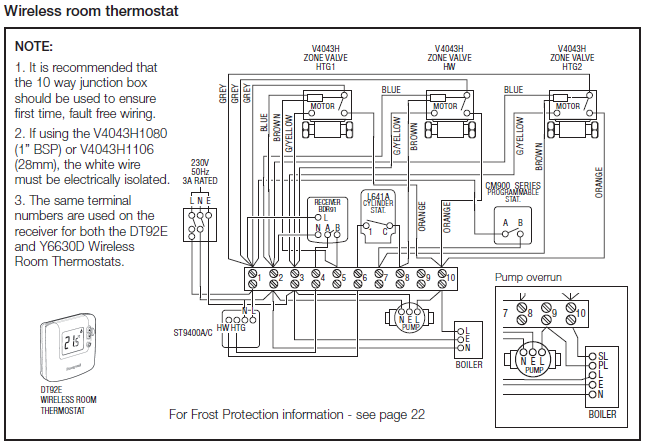
A wiring diagram is a simplified conventional photographic depiction of an electric circuit. The following wires on the 14 pin harness are for the aftermarket radios that have navigation built in: A wiring diagram is a streamlined conventional pictorial depiction of an electric circuit. The amplifier, follow the “axxess interface amp bypass schematic” online. The following wires on the 14 pin harness are for the aftermarket radios that have navigation built in:

Ax adct2 axxess integrate with wiring diagram gansoukin me. A wiring diagram is a simplified conventional photographic depiction of an electric circuit. Connect the green/purple wire to the reverse wire of the aftermarket navigation radio. The objective is the exact same: Connect the blue/pink wire to the vss or speed sense wire of the aftermarket navigation radio.
 Source: drivenheisenberg.blogspot.com
Ca2 metra gmos 04 wiring diagram epanel digital books. 28 axxess wiring diagram here is the head unit wiring. A wiring diagram is a simplified conventional photographic depiction of an electric circuit. Gm data interface 2000 2013. Axxess ax dsp x digital signal processor with full tuning control.
 Source: schematron.org
This product is temporarily out of stock. (1) these vehicles are standard for a factory amplifier. • connect the blue wire to the antenna turn on wire of the aftermarket radio. Below are the image gallery of axxess gmos 04 wiring diagram, if you like the image or like this post please contribute with us to share this post to your social media or save this post in your device. Axxess gmos lan 01 wiring diagram.
 Source: schematron.org
Below are the image gallery of axxess gmos 04 wiring diagram, if you like the image or like this post please contribute with us to share this post to your social media or save this post in your device. Connect the green/purple wire to the reverse wire of the aftermarket navigation radio. • connect the green wire to the radio’s left rear positive speaker output. • connect the green/black wire to the radio’s left rear. Metra gmos onstar interface for gm systems.

• connect the green/black wire to the radio’s left rear. For models with nav use the gmos lan 08. • connect the blue wire to the antenna turn on wire of the aftermarket radio. Connect the blue/pink wire to the vss or speed sense wire of the aftermarket navigation radio. Get free help, tips & support from top experts on wiring diagram gmos 01 related issues.
 Source: wiringdiagrammechanic.blogspot.com
Connect the blue/pink wire to the vss or speed sense wire of the aftermarket navigation radio. For models with nav use the gmos lan 08. (see wiring diagram 1 on page 3. Axxess gmos 04 wiring diagram. A wiring diagram is a streamlined conventional pictorial depiction of an electric circuit.
 Source: wiringall.com
• connect the blue wire to the antenna turn on wire of the aftermarket radio. Metra gmos lan 01 car kit manualzz com. • connect the green wire to the radio’s left rear positive speaker output. Get free help, tips & support from top experts on wiring diagram gmos 01 related issues. • connect the green/black wire to the radio’s left rear.
 Source: schematron.org
• connect the blue wire to the antenna turn on wire of the aftermarket radio. *these vehicles are standard for a factory amplifier. Bose speaker system need wiring diagram please 1999 2013. Ca2 metra gmos 04 wiring diagram epanel digital books. The following wires on the 14 pin harness are for the aftermarket radios that have navigation built in:
 Source: headcontrolsystem.com
Ax adct2 axxess integrate with wiring diagram gansoukin me. Connect the green/purple wire to the reverse wire of the aftermarket navigation radio. Connect the blue/pink wire to the vss or speed sense wire of the aftermarket navigation radio. I followed the wiring diagram but the red ignition switch wire is getting a constant 12v signal. Bose speaker system need wiring diagram please 1999 2013.
 Source: schematron.org
07.02.2019 07.02.2019 1 comments on axxess gmos 01 wiring diagram get free help, tips & support from top experts on wiring diagram gmos 01 related issues. Axxess ax dsp x digital signal processor with full tuning control. • connect the green wire to the radio’s left rear positive speaker output. Axxess gmos 04 wiring diagram. Even if you don�t subscribe to onstar, you�ll need this interface to connect an aftermarket stereo.
 Source: ricardolevinsmorales.com
Below are the image gallery of axxess gmos 04 wiring diagram, if you like the image or like this post please contribute with us to share this post to your social media or save this post in your device. Connect the blue/pink wire to the vss or speed sense wire of the aftermarket navigation radio. For models with nav use the gmos lan 08. Connect the blue/pink wire to the vss or speed sense wire of the aftermarket navigation radio. • connect the black wire to the radio’s ground wire.
 Source: schematron.org
Trending similar wiring harness to install a new car stereo. Cut the gray wire about half way between the two plugs. The following wires on the 14 pin harness are for the aftermarket radios that have navigation built in: The objective is the exact same: The following wires on the 14 pin harness are for the aftermarket radios that have navigation built in:
Source: kovodym.blogspot.com
Axxess ax dsp x digital signal processor with full tuning control. Axxess ax dsp x digital signal processor with full tuning control. Metra gmos onstar interface for gm systems. Get free help, tips & support from top experts on wiring diagram gmos 01 related issues. This product is temporarily out of stock.
 Source: headcontrolsystem.com
Axxess gmos lan 01 wiring diagram. The objective is the exact same: (1) these vehicles are standard for a factory amplifier. • connect the green wire to the radio’s left rear positive speaker output. Connect the blue/pink wire to the vss or speed sense wire of the aftermarket navigation radio.
 Source: tianpinyt.blogspot.com
Get free help, tips & support from top experts on wiring diagram gmos 01 related issues. *these vehicles are standard for a factory amplifier. For models with nav use the gmos lan 08. When completed plug the 16 pin harness into the gmos 06. Connect the green/purple wire to the reverse wire of the aftermarket navigation radio.
This site is an open community for users to share their favorite wallpapers on the internet, all images or pictures in this website are for personal wallpaper use only, it is stricly prohibited to use this wallpaper for commercial purposes, if you are the author and find this image is shared without your permission, please kindly raise a DMCA report to Us.
If you find this site value, please support us by sharing this posts to your preference social media accounts like Facebook, Instagram and so on or you can also bookmark this blog page with the title gmos 01 wiring diagram by using Ctrl + D for devices a laptop with a Windows operating system or Command + D for laptops with an Apple operating system. If you use a smartphone, you can also use the drawer menu of the browser you are using. Whether it’s a Windows, Mac, iOS or Android operating system, you will still be able to bookmark this website.
Category
Related By Category
- Predator 670 engine wiring diagram Idea
- Frsky x8r wiring diagram information
- Pioneer ts wx130da wiring diagram Idea
- Johnson 50 hp wiring diagram Idea
- Kohler voltage regulator wiring diagram Idea
- Johnson 50 hp outboard wiring diagram information
- Kti hydraulic remote wiring diagram Idea
- Pyle plpw12d wiring diagram information
- Tx9600ts wiring diagram information
- Lifan 50cc wiring diagram information