Gm maf sensor wiring diagram Idea
Home » Trending » Gm maf sensor wiring diagram Idea
Your Gm maf sensor wiring diagram images are ready in this website. Gm maf sensor wiring diagram are a topic that is being searched for and liked by netizens now. You can Get the Gm maf sensor wiring diagram files here. Find and Download all free photos.
If you’re looking for gm maf sensor wiring diagram pictures information related to the gm maf sensor wiring diagram topic, you have come to the ideal blog. Our site always provides you with hints for refferencing the maximum quality video and image content, please kindly search and locate more informative video content and images that match your interests.
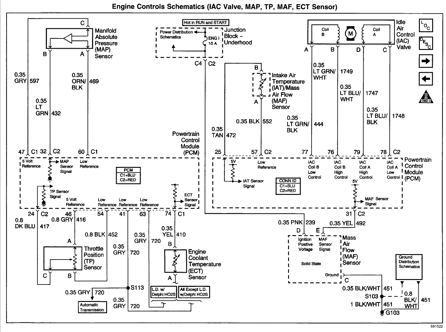
Gm Maf Sensor Wiring Diagram. 14 bm mount 350 5 7 0007 142b flywheel. 5 wire gm mass air flow sensor connector pigtail maf ls1 ls2 ls6 fitment information: Air flow maf sensor circuit diagram for mass air flow sensor wiring diagram, image size 552 x 342 px, and to view image details please click the image. It shows the components of the circuit as simplified shapes, and the capability and signal contacts in.
 Where do I locate the IAT sensor on a 2001 chevy suburban From justanswer.com
There�s only 3 for the maf itself: On the other hand, this diagram is a simplified version of this arrangement. What is wiring diagram for air flow sensor? Posted on jun 22, 2009 Find the black sensor ground wire and the red/blue intake air temperature sensor wire going into the back of the maf plug and cut them. Description and operation mass air flow (maf) sensor the mass air flow sensor (maf sensor) (12b579):
This type of gm mass air flow (maf) sensor is used in a lot of gm makes and models, to find out if this article applies to your specific gm (cadillac, chevy, buick, gmc) vehicle, take a look at the �applies to� list.
The diagram offers visual representation of an electrical arrangement. Weld the boss in place before installing the sensor. 2016 silverado ccsb 5.3/6l80e, not as slow but still heavy. There’ll be principal lines that are represented by l1, l2, l3, and so on. 5 7 vortec wiring diagram in addition 97 chevy blazer fuel filter location in addition gm maf sensor wiring diagram in addition lt1 conversion wiring diagram jaguar also chevy k vacuum hose diagram as well as where is a crank sensor for a 96 s 10 2 2 4 cylinder 2 wheel drive. But if your maf is not even working at all, you need to start there.
Source: wiringschemas.blogspot.com
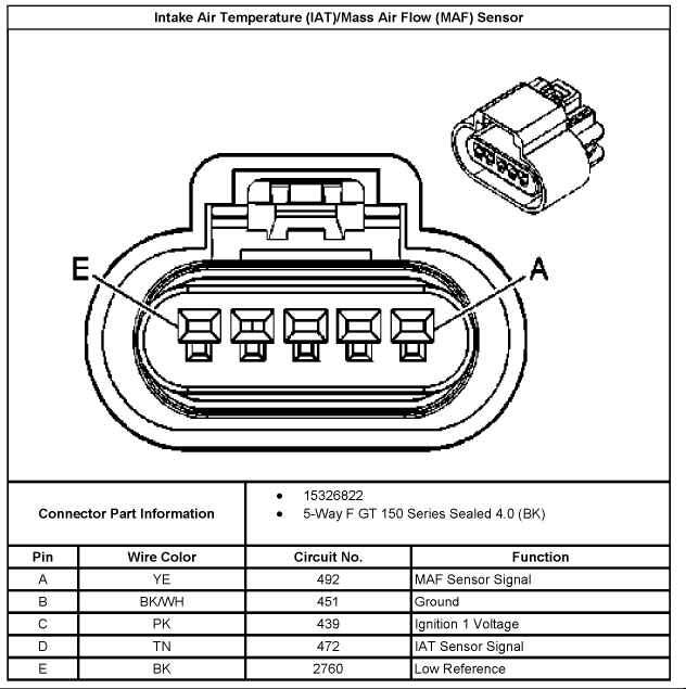
B 0.8 bk/wh 451 ground. There are 6 pins visible in the connector. The hot wire is a feed power source that is taken from the car computer (ecu). Yes it has a sensor and they are color coded however i don�t think it�s called a maf or map sensor that’s a gm name, there would be three wires on it on ground one 5 volts reference and one for connection to the computer to tell the computer how much air flow there is, and the reading would be from 1.5 volts to 4 volts. P0102 mass air flow low frequency.
 Source: justanswer.com
5 7 vortec wiring diagram in addition 97 chevy blazer fuel filter location in addition gm maf sensor wiring diagram in addition lt1 conversion wiring diagram jaguar also chevy k vacuum hose diagram as well as where is a crank sensor for a 96 s 10 2 2 4 cylinder 2 wheel drive. C 0.5 pk 539 ignition 1 voltage. Gm maf sensor wiring diagram. There�s only 3 for the maf itself: Description and operation mass air flow (maf) sensor the mass air flow sensor (maf sensor) (12b579):
Source: schematicandwiringdiagram.blogspot.com
Maf sensor connector pinout on l, l, l engines. P0102 mass air flow low frequency. In this test, tutorial, i�ll show you how to test the mass air flow sensor to see if it�s bad (and lighting up the check engine light) or not. This makes the procedure for assembling circuit simpler. You can often count on wiring diagram as an essential reference that will help you conserve money and time.
 Source: ls1tech.com
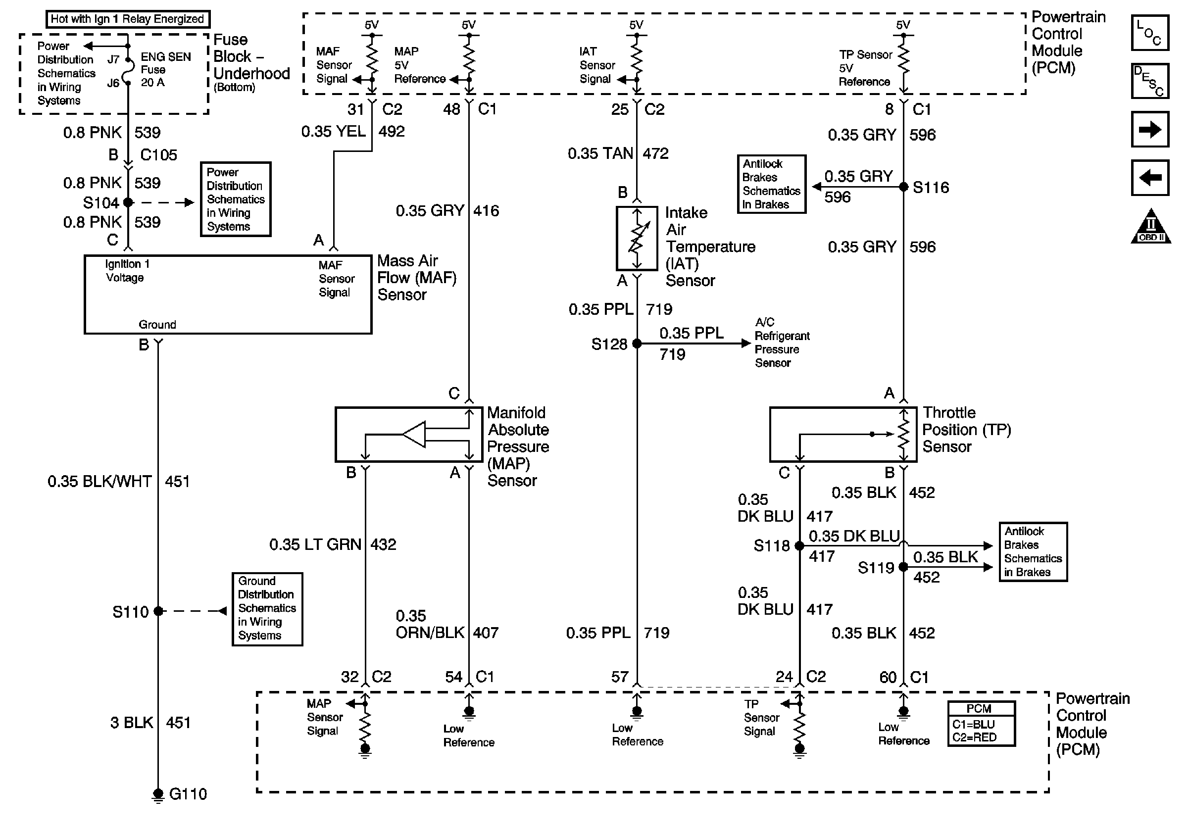
The second picture is the wiring diagram for the maf/iat assembly. A 0.35 ye 492 mass air flow (maf) sensor signal. P0102 mass air flow low frequency. There�s only 3 for the maf itself: B 0.8 bk/wh 451 ground.
 Source: justanswer.com
The second picture is the wiring diagram for the maf/iat assembly. Uses a hot wire sensing element to measure the amount of air entering the engine; Maf sensor connector pinout on l, l, l engines. There�s only 3 for the maf itself: All you�ll need, to test the maf sensor (with this tutorial) is a multimeter that can read hertz frequency (if you don�t have one, i�ve made a recommendation on where you can buy a reasonably priced.
 Source: 3.ncceconnect.org
Is mounted on the corner of the engine air cleaner (acl) (9600). All you�ll need, to test the maf sensor (with this tutorial) is a multimeter that can read hertz frequency (if you don�t have one, i�ve made a recommendation on where you can buy a reasonably priced. P0102 mass air flow low frequency. This type of gm mass air flow (maf) sensor is used in a lot of gm makes and models, to find out if this article applies to your specific gm (cadillac, chevy, buick, gmc) vehicle, take a look at the �applies to� list. 5 7 vortec wiring diagram in addition 97 chevy blazer fuel filter location in addition gm maf sensor wiring diagram in addition lt1 conversion wiring diagram jaguar also chevy k vacuum hose diagram as well as where is a crank sensor for a 96 s 10 2 2 4 cylinder 2 wheel drive.
 Source: schematron.org
Gm 3 bar map sensor wiring diagrampdf size. Air flow maf sensor circuit diagram for mass air flow sensor wiring diagram, image size 552 x 342 px, and to view image details please click the image. All you need (to diagnose and troubleshoot the maf sensor) is a digital multimeter capable of reading hertz (hz) frequency. Uses a hot wire sensing element to measure the amount of air entering the engine; 5 wire gm mass air flow sensor connector pigtail maf ls1 ls2 ls6 fitment information:
 Source: fusewiring.blogspot.com
All you need (to diagnose and troubleshoot the maf sensor) is a digital multimeter capable of reading hertz (hz) frequency. If the wires are okay, replace mass. The second picture is the wiring diagram for the maf/iat assembly. A map or a maf will have 3 wires. Does any one have a wiring diagram for maf sensor on an 08 lmm?
 Source: wiringschemas.blogspot.com
Maf sensor connector pinout on l, l, l engines. On the other hand, this diagram is a simplified version of this arrangement. But if your maf is not even working at all, you need to start there. Gm 3 bar map sensor wiring diagrampdf size. The maf airflow freq table would need to be adjusted if the maf�s are different styles.
Source: dsmtuners.com
As stated previous, the traces at a maf wiring diagram signifies wires. It shows the components of the circuit as simplified shapes, and the capability and signal contacts in. The second picture is the wiring diagram for the maf/iat assembly. E 0.35 tn 472 intake air. Description and operation mass air flow (maf) sensor the mass air flow sensor (maf sensor) (12b579):
 Source: wiringall.com
Does any one have a wiring diagram for maf sensor on an 08 lmm? It shows the components of the circuit as simplified shapes, and the capability and signal contacts in. But if your maf is not even working at all, you need to start there. All you need (to diagnose and troubleshoot the maf sensor) is a digital multimeter capable of reading hertz (hz) frequency. On the other hand, this diagram is a simplified version of this arrangement.
Source: wiringschemas.blogspot.com
Find the black sensor ground wire and the red/blue intake air temperature sensor wire going into the back of the maf plug and cut them. There are 6 pins visible in the connector. Weld the boss in place before installing the sensor. This type of gm mass air flow (maf) sensor is used in a lot of gm makes and models, to find out if this article applies to your specific gm (cadillac, chevy, buick, gmc) vehicle, take a look at the �applies to� list. Found this, just want to match everything up.
 Source: justanswer.com
As stated previous, the traces at a maf wiring diagram signifies wires. There’ll be principal lines that are represented by l1, l2, l3, and so on. B 0.8 bk/wh 451 ground. As stated previous, the traces at a maf wiring diagram signifies wires. The maf sensor in the middle of the straight induction section, ensuring that the middle of the mounting boss is at least 10 inches from the throttle body.
 Source: ls1tech.com
As stated previous, the traces at a maf wiring diagram signifies wires. Occasionally, the cables will cross. The second picture is the wiring diagram for the maf/iat assembly. We use cookies to give you the best possible experience on our website. Maf sensor wiring diagram 1997 1999 ford 4 6l 5 4l index of articles.
Source: wiringschemas.blogspot.com
This makes the procedure for assembling circuit simpler. This is a reference voltage, which means the car ecu powers the maf sensor through this wire. Maf sensor connector pinout on l, l, l engines. For resources on getting wiring diagrams for your vehicle, see our article: There�s only 3 for the maf itself:
![[DIAGRAM] Toyota Maf Sensor Wiring Diagram FULL Version HD [DIAGRAM] Toyota Maf Sensor Wiring Diagram FULL Version HD](https://ww2.justanswer.com/uploads/fordguy4u/2012-05-07_125306_a1.jpg) Source: kandiagramx5.legrandbleu.it
Source: kandiagramx5.legrandbleu.it
There�s only 3 for the maf itself: But if your maf is not even working at all, you need to start there. Does your sensor have only 5 pins? Maf sensor connector pinout on l, l, l engines. The second picture is the wiring diagram for the maf/iat assembly.
 Source: justanswer.com
Does your sensor have only 5 pins? Maf sensor connector pinout on l, l, l engines. B 0.8 bk/wh 451 ground. C 0.5 pk 539 ignition 1 voltage. This makes the procedure for assembling circuit simpler.
 Source: justanswer.com
The maf airflow freq table would need to be adjusted if the maf�s are different styles. Check power at the harness and such. If that is all good then the new sensor might be bad. Gm 3 bar map sensor wiring diagrampdf size. With this sort of an illustrative guide, you’ll be able to.
This site is an open community for users to do submittion their favorite wallpapers on the internet, all images or pictures in this website are for personal wallpaper use only, it is stricly prohibited to use this wallpaper for commercial purposes, if you are the author and find this image is shared without your permission, please kindly raise a DMCA report to Us.
If you find this site value, please support us by sharing this posts to your favorite social media accounts like Facebook, Instagram and so on or you can also bookmark this blog page with the title gm maf sensor wiring diagram by using Ctrl + D for devices a laptop with a Windows operating system or Command + D for laptops with an Apple operating system. If you use a smartphone, you can also use the drawer menu of the browser you are using. Whether it’s a Windows, Mac, iOS or Android operating system, you will still be able to bookmark this website.
Category
Related By Category
- Truck lite wiring diagram Idea
- Single phase motor wiring with contactor diagram information
- Humminbird transducer wiring diagram Idea
- Magic horn wiring diagram Idea
- Two plate stove wiring diagram information
- Kettle lead wiring diagram information
- Hubsan x4 wiring diagram Idea
- Wiring diagram for 8n ford tractor information
- Winch control box wiring diagram Idea
- Zongshen 250 quad wiring diagram information