Gm 3 bar map sensor wiring diagram Idea
Home » Trending » Gm 3 bar map sensor wiring diagram Idea
Your Gm 3 bar map sensor wiring diagram images are ready. Gm 3 bar map sensor wiring diagram are a topic that is being searched for and liked by netizens today. You can Get the Gm 3 bar map sensor wiring diagram files here. Download all royalty-free photos and vectors.
If you’re looking for gm 3 bar map sensor wiring diagram pictures information related to the gm 3 bar map sensor wiring diagram interest, you have come to the right blog. Our website always gives you suggestions for viewing the maximum quality video and picture content, please kindly surf and locate more informative video content and images that match your interests.
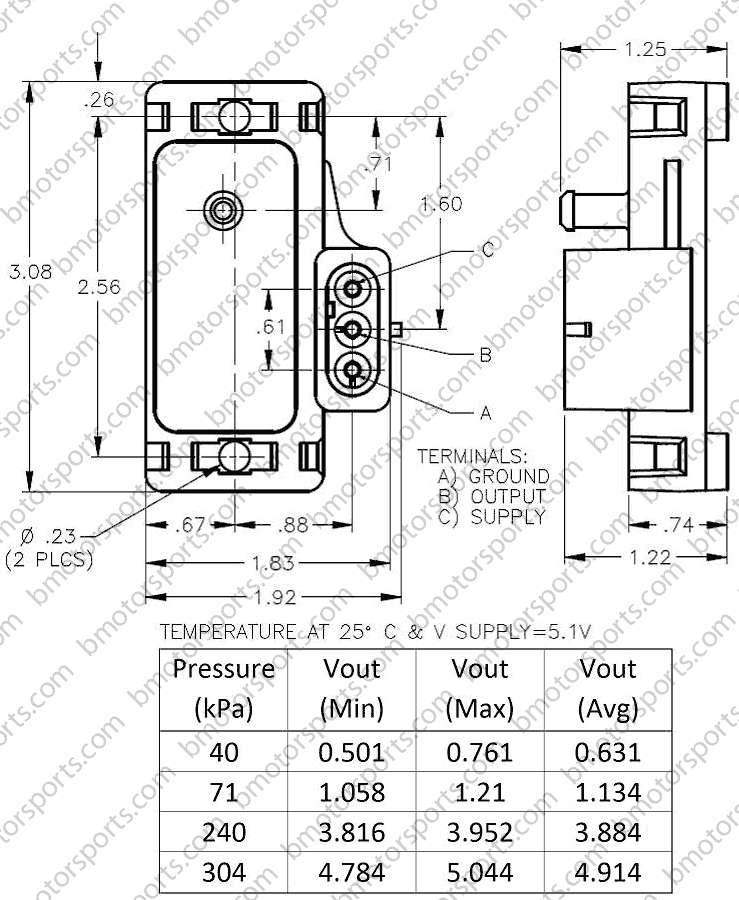
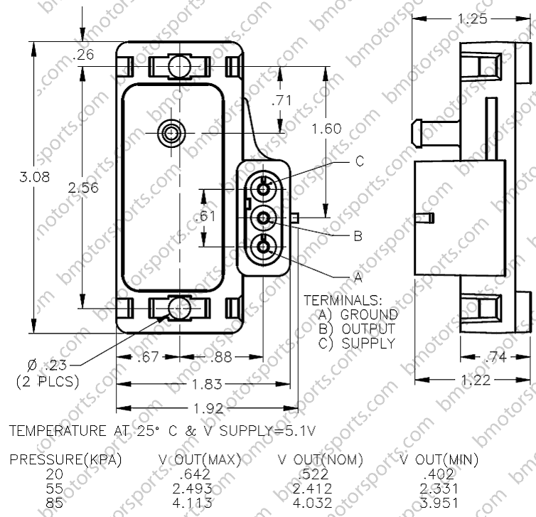
Gm 3 Bar Map Sensor Wiring Diagram. The baro sensor can be the same specification as the map sensor, but it can be a different one as well. Connect the map sensor to a vacuum pump. Matching plug and 3 pins. Whether your engine has forced induction or is naturally aspirated, these holley map sensors will keep your engine performing at its best.
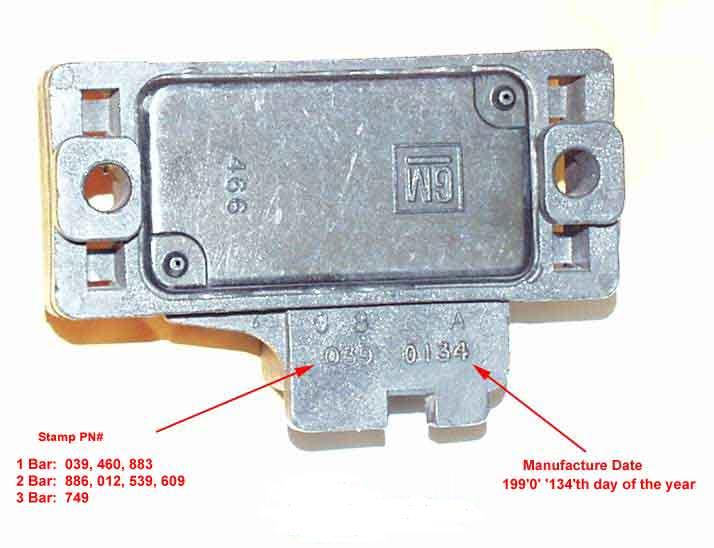 MAP Sensors and how they work From fastfieros.com
Turn on the ignition (but do not start the engine). Gm 3 bar map sensor wiring diagram. It is possible that detroit is slightly above sea level, and you can use 12.11 in the formula for 1 mile above sea level. Since he is maf he will also have to wire in the iat sensor to pin 3. Honda map sensor wiring diagram. Just find the wiring diagram for your car and mix+match, make sure you just tap into the stock wires, don�t cut them in.
Gm 3 bar map sensor wiring diagram.
Installed it just like the wiring diagram shows. Part number 16040749 $59 shipped. The baro sensor can be the same specification as the map sensor, but it can be a different one as well. Running the ls9 map sensor on both options and breaking out the iat post rotors. Just find the wiring diagram for your car and mix+match, make sure you just tap into the stock wires, don�t cut them in. In many states, it is unlawful to tamper with your vehicle�s emissions equipment.
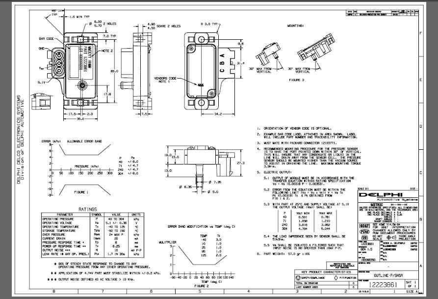 Source: kelvin-okl.blogspot.com
1996 1998 map sensor circuit diagram 1 toyota 3 pin connector dtc p0107 how to test your ls1 wire harness repair kit 2 gm bar 6 pigtail connectors harnesses denso uncrimped micro introduction cts turbo wiring for 5 aem 97251137 camaro5 chevy motoall t replacement plug with leads. I have a new dominator efi system. The map sensor is wired to the dme via 3 wires. Instructions i recived with mine: 1) gm 3 bar map sensor from www.gmpartsdirect.com.

Whether your engine has forced induction or is naturally aspirated, these holley map sensors will keep your engine performing at its best. Vref and ground can be shared. The baro sensor can be the same specification as the map sensor, but it can be a different one as well. I hooked up my 3bar gm map sensor using the above wiring diagram. This wire is white on most b series and d series engines, and will be green with a red stripe on the later k series engines.

Now the car will not start. Honda car pdf manual wiring diagram fault codes dtc. Holley efi 558 466 weatherpak to gt stainless steel map adapter harness. Gm 3 bar map sensor install for use with dsmlink vfaq. Part 2 how to test the map sensor 1 5l honda civic.
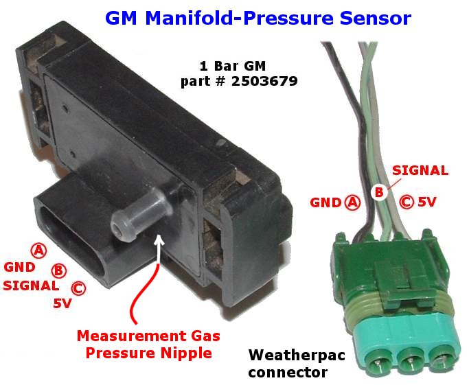 Source: wbo2.com
The hyundai diagram just shows you what pin does what. Stainless pressure sensor = caliper use a ss pressure sensor where you need exact details of the pressure. The final part of our how to install a 3 bar map sensor diy guide is the map signal wire. Matching plug and 3 pins. Whereas old sensor wiring is.
![[HF_2113] 2013 Ford Map Sensor Wiring Diagram Schematic Wiring [HF_2113] 2013 Ford Map Sensor Wiring Diagram Schematic Wiring](https://static-resources.imageservice.cloud/125162/3-bar-map-sensor-wiring-wiring-diagram-data-schema.jpg) Source: anal.acion.elinu.numap.mohammedshrine.org
Source: anal.acion.elinu.numap.mohammedshrine.org
Make sure you are leaving this wire last, as you’ll want to measure the output from your map sensor to test it. Since he is maf he will also have to wire in the iat sensor to pin 3. In many states, it is unlawful to tamper with your vehicle�s emissions equipment. Now the car will not start. I hooked up my 3bar gm map sensor using the above wiring diagram.
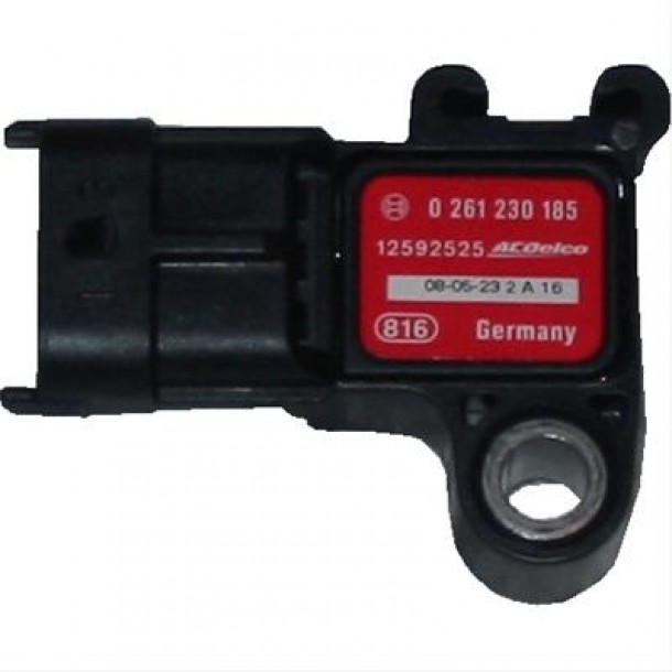 Source: efisystempro.com
Ignition system wiring diagram 1996 1997 2 2l honda accord ex. The map sensor is wired to the dme via 3 wires. The onboard is no good after 21.9 ish so i went out and purchased a 3 bar gm map sensor. Map signal so if i just connect 5 and gnd and wit multi meter i measure number 4th pin thats map out i got 169v. Map sensor is recommended for forced induction applications.
 Source: diyautotune.com
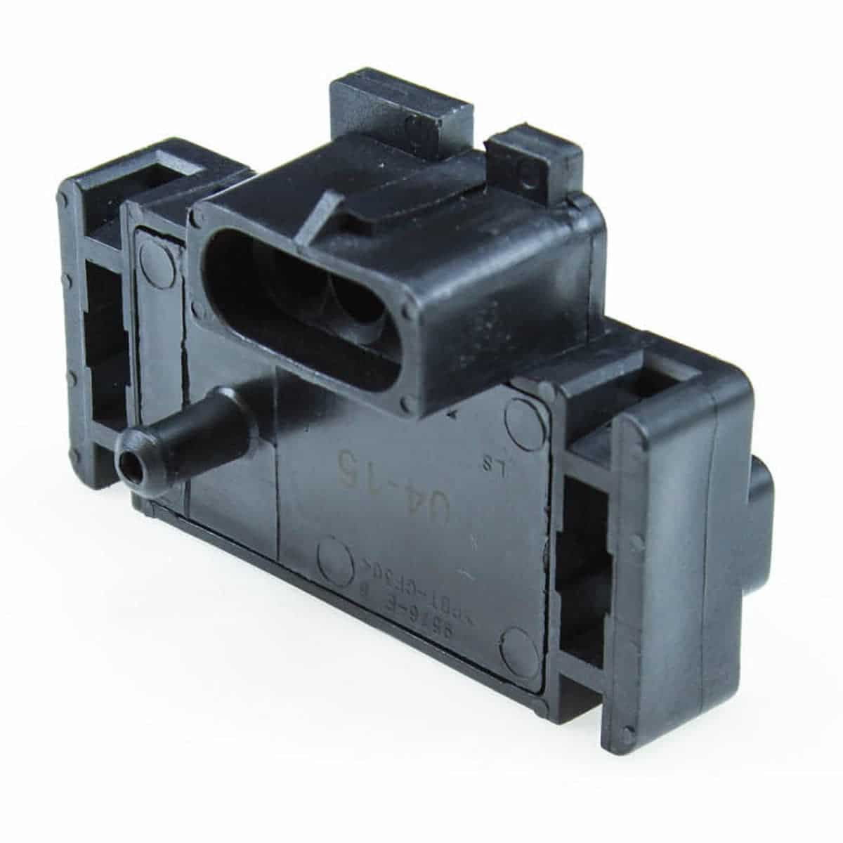
Colors are the harness and numbers are location. This is a factory 3 bar map sensor that is a great upgrade for forced induction applications. 92mm or 102mm* billet aluminum throttle body. Buy in monthly payments with affirm on orders over $50. Map sensor is easy, set your linear and offset settings to 305/10.33 for that map sensor.
 Source: boostbysmith.com
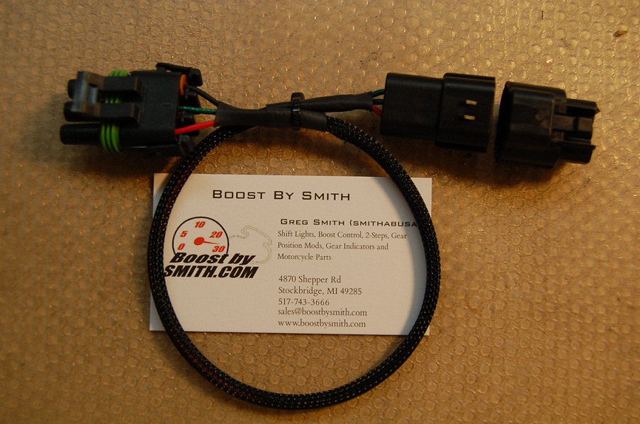
They are not in order. Map sensor is easy, set your linear and offset settings to 305/10.33 for that map sensor. Buy in monthly payments with affirm on orders over $50. Gm 3 bar map sensor calibration g4 link engine management forums gm map sensor wiring diagram wiring diagram is a simplified conventional pictorial representation of an electrical circuit. This is a factory 3 bar map sensor that is a great upgrade for forced induction applications.
 Source: diyautotune.com
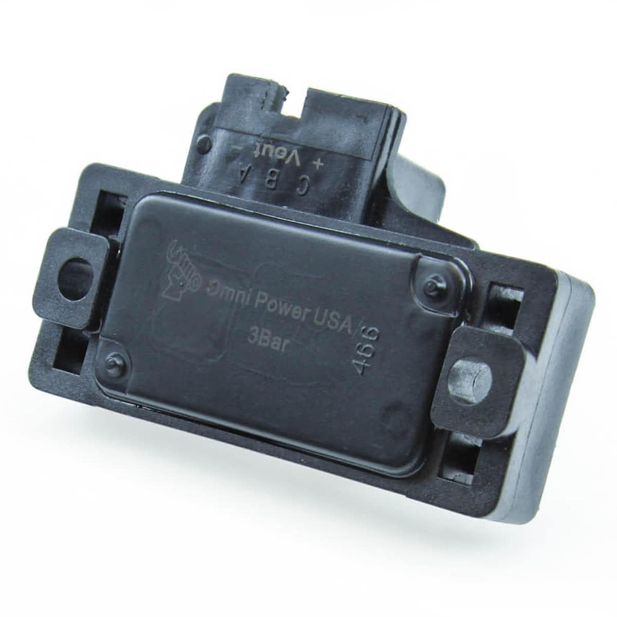
This is a factory 3 bar map sensor that is a great upgrade for forced induction applications. Whereas old sensor wiring is. Testing the map voltage signal to get this show on the road, we�re gonna� test the map voltage signal and see if it decreases/increases as you apply/release vacuum to the sensor. Gm 3 bar map sensor install for use with dsmlink vfaq. #13 · dec 10, 2009.
 Source: diyautotune.com
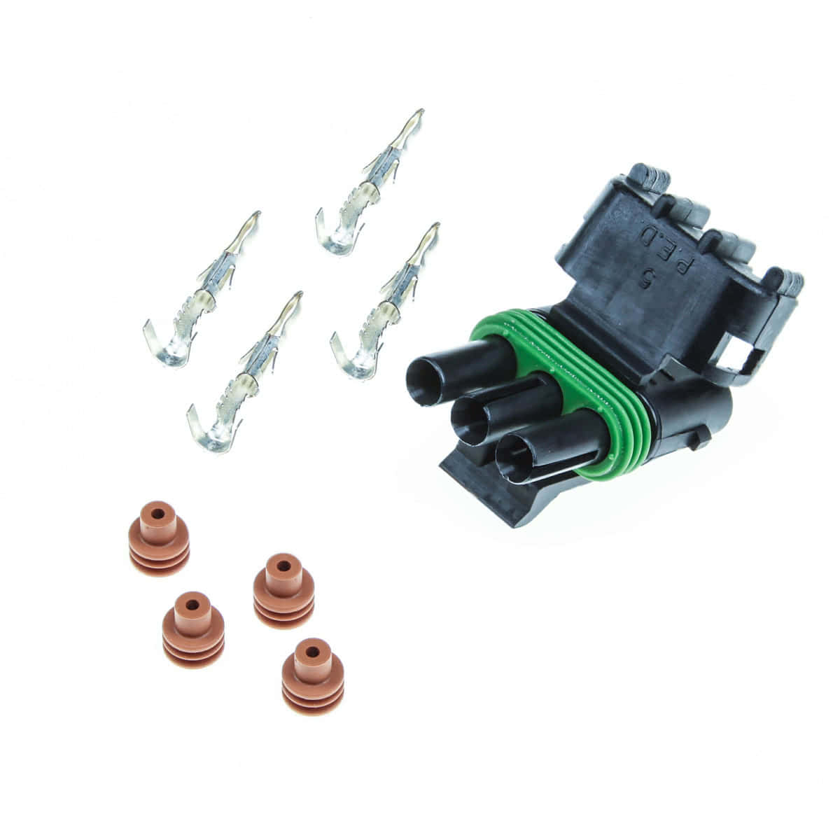
Instructions i recived with mine: If you plan to run speed density you may also have to upgrade the tune file to support that sensor. The sensor produces a linear output between 0.6v and 4.9v corrisponding to a range of 40kpa to 204kpa (aprox. A map sensor has 3 wires (ground, +5v source, and signal). It is possible that detroit is slightly above sea level, and you can use 12.11 in the formula for 1 mile above sea level.
 Source: diyautotune.com
The gm ls1 manifold absolute pressure sensor is part number 12614970 and. #13 · dec 10, 2009. I did rewire it but it was not in the same wire location i wired it per the gm directions which i will list below. Turn on the ignition (but do not start the engine). Running the ls9 map sensor on both options and breaking out the iat post rotors.
Source: wiring89.blogspot.com
Colors are the harness and numbers are location. Gm 3 bar map sensor install for use with dsmlink vfaq. Read free 99 toyota camry engine diagram fuse toyota camry 2 2 liter engine part 1 of 10 remove engine tranny rebuild 1994 toyota camry coolant temperature sensor replacement 93 98 toyota t100 2 7l. Gm 3 bar map sensor calibration g4 link engine management forums gm map sensor wiring diagram wiring diagram is a simplified conventional pictorial representation of an electrical circuit. The map sensor is wired to the dme via 3 wires.
 Source: world-mapsss.blogspot.com
Now the car will not start. Since he is maf he will also have to wire in the iat sensor to pin 3. This is a factory 3 bar map sensor that is a great upgrade for forced induction applications. Map sensor is easy, set your linear and offset settings to 305/10.33 for that map sensor. The hyundai diagram just shows you what pin does what.
 Source: bmotorsports.com
I was able to get a new connector but trying to know if anyone has had this problem? The gm ls1 manifold absolute pressure sensor is part number 12614970 and. 1987 ford ranger map sensor; 2021 jun 16 0619 rating. 1) gm 3 bar map sensor from www.gmpartsdirect.com.
 Source: fastfieros.com
The correction involves swapping the power and ground terminals to it. This wire is white on most b series and d series engines, and will be green with a red stripe on the later k series engines. If you plan to run speed density you may also have to upgrade the tune file to support that sensor. Buy in monthly payments with affirm on orders over $50. Turn on the ignition (but do not start the engine).
 Source: forum.diyefi.org
3 bar gm map sensor. The correction involves swapping the power and ground terminals to it. Holley efi 558 466 weatherpak to gt stainless steel map adapter harness. Connect the map sensor to a vacuum pump. I have a new dominator efi system.
Source: world-mapsss.blogspot.com
The correction involves swapping the power and ground terminals to it. Holley efi 558 466 weatherpak to gt stainless steel map adapter harness. Connect the map sensor to a vacuum pump. Bosch maf sensor wiring diagram. I have a new dominator efi system.
 Source: phearable.net
Now the car will not start. I have 94 gsr and i�m not sure what wires from the gm 3 bar attach to the oem map sensor wires.the oem map wires are white/yellow, green/white and. 1997 toyota corolla engine diagram wiring diagram centre. The above manifold absolute pressure (map) sensor fits the following vehicles: 4 bar map sensor 3 wire wiring plug boost air turbo saab gm vauxhall opel harnes.
This site is an open community for users to submit their favorite wallpapers on the internet, all images or pictures in this website are for personal wallpaper use only, it is stricly prohibited to use this wallpaper for commercial purposes, if you are the author and find this image is shared without your permission, please kindly raise a DMCA report to Us.
If you find this site beneficial, please support us by sharing this posts to your own social media accounts like Facebook, Instagram and so on or you can also bookmark this blog page with the title gm 3 bar map sensor wiring diagram by using Ctrl + D for devices a laptop with a Windows operating system or Command + D for laptops with an Apple operating system. If you use a smartphone, you can also use the drawer menu of the browser you are using. Whether it’s a Windows, Mac, iOS or Android operating system, you will still be able to bookmark this website.
Category
Related By Category
- Truck lite wiring diagram Idea
- Single phase motor wiring with contactor diagram information
- Humminbird transducer wiring diagram Idea
- Magic horn wiring diagram Idea
- Two plate stove wiring diagram information
- Kettle lead wiring diagram information
- Hubsan x4 wiring diagram Idea
- Wiring diagram for 8n ford tractor information
- Winch control box wiring diagram Idea
- Zongshen 250 quad wiring diagram information