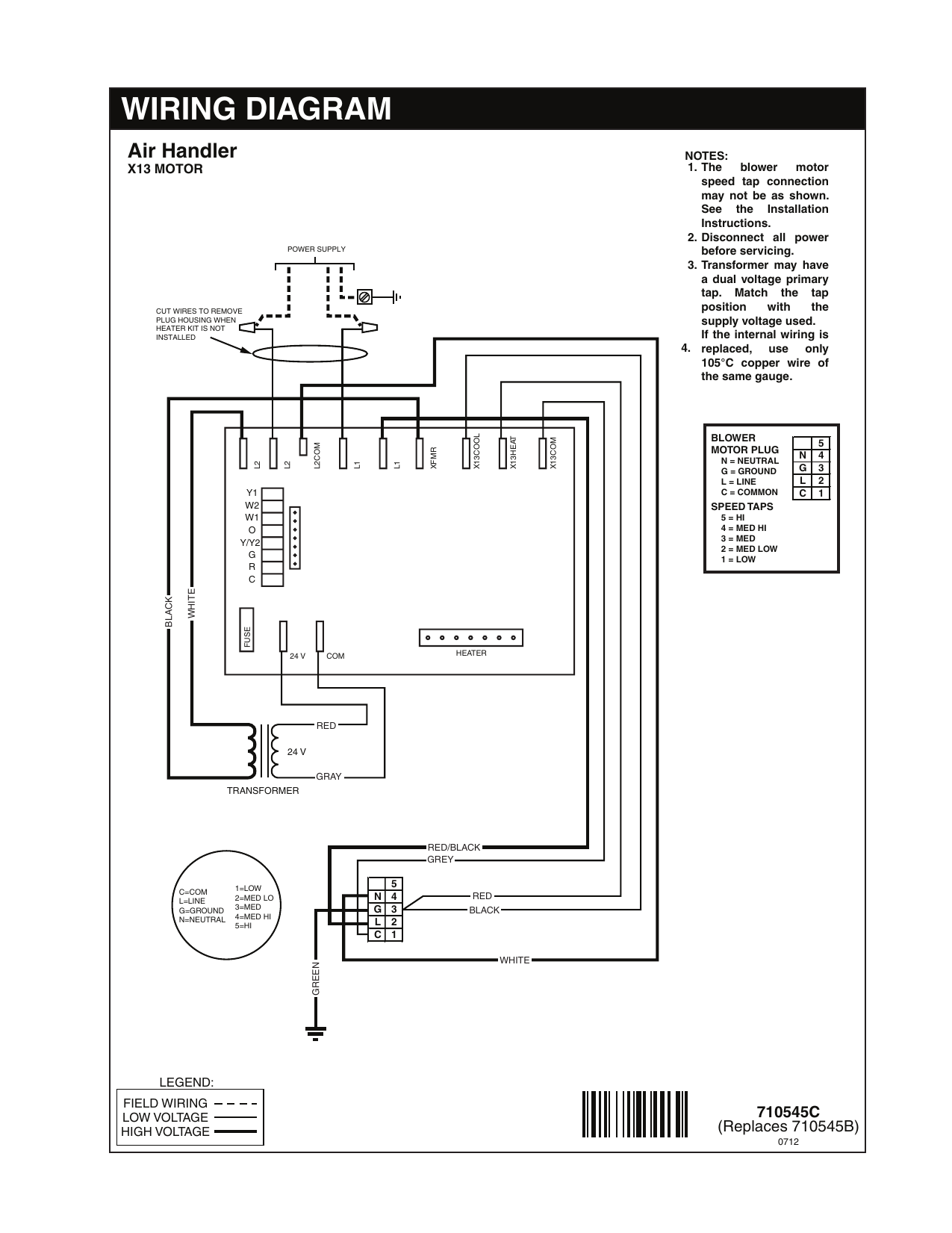
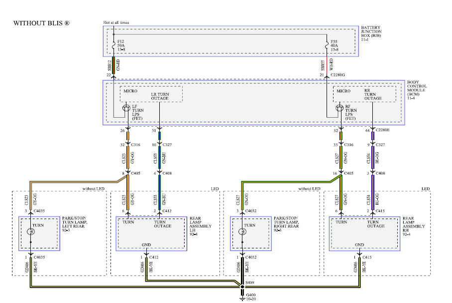
Gibson air handler wiring diagram Idea
Home » Trending » Gibson air handler wiring diagram Idea
Your Gibson air handler wiring diagram images are ready in this website. Gibson air handler wiring diagram are a topic that is being searched for and liked by netizens now. You can Get the Gibson air handler wiring diagram files here. Find and Download all free photos and vectors.
If you’re looking for gibson air handler wiring diagram pictures information linked to the gibson air handler wiring diagram keyword, you have come to the ideal site. Our website always provides you with suggestions for refferencing the highest quality video and picture content, please kindly search and find more enlightening video content and graphics that match your interests.
Gibson Air Handler Wiring Diagram. A wiring diagram and a ratings label are supplied with the electric heater kit. June 21, 2021 on air handler wiring diagram. 55 new potential relay wiring diagram electrical circuit diagram ac capacitor electrical diagram. Opening of dft during defrost or interval period resets the interval to 0.
 Nordyne Air Handler Wiring Diagram Free Wiring Diagram From ricardolevinsmorales.com
Check to make sure unit wiring to circuit breaker load lugs match that shown on the unit wiring diagram. Heat pump thermostat wiring chart diagram hvac the following graphics are meant as a guide only. Opening of dft during defrost or interval period resets the interval to 0. Replace single point wiring jumper bar, if it is used, on line side of breaker and tighten securely. Goodman package unit wiring diagram you will need a comprehensive skilled and easy to understand wiring diagram. Low voltage is the voltage that is used to control the unit from a thermostat or other single phase will be two power wires and a ground three phase will be the thermostat.
As stated earlier, the traces at a air conditioner wiring diagram pdf signifies wires.
The color of wire r is usually red and c is black. Heater kit, 3kw & 5kw, single phase wiring diagram. With dft closed and y closed, compressor run time is accumulated. The color of wire r is usually red and c is black. Wiring diagram sony car stereo; Fan will not come on in the on position or your fan will not come on when you turn the thermostat down in the air conditioning mode.

Low voltage is the voltage that is used to control the unit from a thermostat or other single phase will be two power wires and a ground three phase will be the thermostat. Mitsubishi triton wiring diagram pdf I just finished installing a new ac system and the air handler did not come with a wiring diagram for thermostat and compressor contact hookup. Check to make sure unit wiring to circuit breaker load lugs match that shown on the unit wiring diagram. Multi ple power sour ces ma y be present.
 Source: wiring121.blogspot.com
Gas182g2a1 central air conditioner 449ec gibson air handler wiring diagram gac103g1a1 central air conditioner window ac air conditioner maintenance. Multi ple power sour ces ma y be present. The color of wire r is usually red and c is black. Instructions b) the type of thermostat (2 or 5 wire) for the installation. There will be primary lines that are represented by l1, l2, l3, and so on.
![[DIAGRAM] Gibson Ac Unit Diagram FULL Version HD Quality [DIAGRAM] Gibson Ac Unit Diagram FULL Version HD Quality](https://ricardolevinsmorales.com/wp-content/uploads/2018/09/goodman-ac-unit-wiring-diagram-wiring-diagram-for-goodman-ac-unit-best-mcquay-air-conditioner-wiring-diagram-valid-wiring-diagram-for-11a.jpg) Source: cumwirexi.gruppobm.it
Source: cumwirexi.gruppobm.it
Installer:please leave these installation instructions with the homeowner. A wiring diagram is a kind of schematic which utilizes abstract photographic icons to show all the interconnections of elements in a system. Gibson sg standard wiring diagram effectively read a wiring diagram, one has to know how typically the components within the program operate. June 21, 2021 on air handler wiring diagram. Technical installation instructions replacement parts list wiring diagram consumer materials other bulletins.
 Source: wiring04.blogspot.com
Variable speed air handler wiring diagram. Wiring diagram sony car stereo; Relay wiring diagram ac wiring electrical diagram air handler. Thermostat wiring and wire color chart thermostat wiring colors code. Technical installation instructions replacement parts list wiring diagram consumer materials other bulletins.

Op e nsdu r i gf o t.r a: Goodman aruf air handler wiring diagram. Multi ple power sour ces ma y be present. Instructions for nordyne furnaces are given below. With dft closed and y closed, compressor run time is accumulated.
 Source: easywiring.info
Multi ple power sour ces ma y be present. Gibson nordyne air handler wiring diagram gb3bm. June 21, 2021 on air handler wiring diagram. Heater kit, 3kw & 5kw, single phase wiring diagram. A wiring diagram and a ratings label are supplied with the electric heater kit.
 Source: galvinconanstuart.blogspot.com
I just finished installing a new ac system and the air handler did not come with a wiring diagram for thermostat and compressor contact hookup. 55 new potential relay wiring diagram electrical circuit diagram ac capacitor electrical diagram. Goodman aruf air handler wiring diagram. Gas182g2a1 central air conditioner 449ec gibson air handler wiring diagram gac103g1a1 central air conditioner window ac air conditioner maintenance. Instructions b) the type of thermostat (2 or 5 wire) for the installation.
 Source: wiring07.blogspot.com
55 new potential relay wiring diagram electrical circuit diagram ac capacitor electrical diagram. Gibson nordyne air handler wiring diagram gb3bm. There will be primary lines that are represented by l1, l2, l3, and so on. Fan will not come on in the on position or your fan will not come on when you turn the thermostat down in the air conditioning mode. Open when y is off.
 Source: wirgram.blogspot.com
Check to make sure unit wiring to circuit breaker load lugs match that shown on the unit wiring diagram. A inside the unit the main power cord is split to. This part has (2) mode for operation which are: Injunction of 2 wires is generally indicated by black dot to the junction of 2 lines. Heater kit, 3kw & 5kw, single phase wiring diagram.
 Source: gallery4k.com
Mitsubishi triton wiring diagram pdf I just finished installing a new ac system and the air handler did not come with a wiring diagram for thermostat and compressor contact hookup. 55 new potential relay wiring diagram electrical circuit diagram ac capacitor electrical diagram. Opening of dft during defrost or interval period resets the interval to 0. Gibson sg standard wiring diagram effectively read a wiring diagram, one has to know how typically the components within the program operate.
 Source: santeesthetic.com
The unit, when combined with our engineered coils or air handlers, offers a line of quality, split system cooling equipment. Op e nsdu r i gf o t.r a: Fan will not come on in the on position or your fan will not come on when you turn the thermostat down in the air conditioning mode. A wiring diagram and a ratings label are supplied with the electric heater kit. As stated previous the lines at a goodman heat pump thermostat wiring diagram represents wires.
 Source: ricardolevinsmorales.com
2hp 30 v c m x closed when y is fon. The full form of psc is permanent split capacitor. Wiring diagram for gibson flying v; Gibson nordyne air handler wiring diagram gb3bm. Op e nsdu r i gf o t.r a:
 Source: ricardolevinsmorales.com
Gibson sg standard wiring diagram effectively read a wiring diagram, one has to know how typically the components within the program operate. Double check wires and lugs to make sure all are secure and tight. 2hp 30 v c m x closed when y is fon. Heat pump thermostat wiring chart diagram hvac the following graphics are meant as a guide only. Gibson sg standard wiring diagram effectively read a wiring diagram, one has to know how typically the components within the program operate.
 Source: gramwir.blogspot.com
Goodman package unit wiring diagram you will need a comprehensive skilled and easy to understand wiring diagram. The unit, when combined with our engineered coils or air handlers, offers a line of quality, split system cooling equipment. Units are ideally sized for slab or rooftop mounting. 2hp 30 v c m x closed when y is fon. A wiring diagram is a kind of schematic which utilizes abstract photographic icons to show all the interconnections of elements in a system.
 Source: ricardolevinsmorales.com
Check out more product details by visiting our product pages or get in touch with your local gibson contractor to find out the best hvac system for your home. Open when y is off. Injunction of 2 wires is generally indicated by black dot to the junction of 2 lines. Low voltage is the voltage that is used to control the unit from a thermostat or other single phase will be two power wires and a ground three phase will be the thermostat. Thermostat wiring and wire color chart thermostat wiring colors code.
 Source: schematica96.blogspot.com
Attach the wiring diagram to the blower housing. Op e nsdu r i gf o t.r a: For instance , if a module will be powered up and it sends out the signal of 50 percent the voltage in addition to the technician would not know this, he would think he offers a problem, as he or she would expect a 12v signal. 8 horizontal right is the default factory configuration for the units. Multi ple power sour ces ma y be present.
 Source: easywiring.info
Variable speed air handler wiring diagram. I just finished installing a new ac system and the air handler did not come with a wiring diagram for thermostat and compressor contact hookup. Fan will not come on in the on position or your fan will not come on when you turn the thermostat down in the air conditioning mode. Replace single point wiring jumper bar, if it is used, on line side of breaker and tighten securely. The js5bd series air conditioners offer exceptional performance.
 Source: schematron.org
Goodman aruf air handler wiring diagram. Low voltage is the voltage that is used to control the unit from a thermostat or other single phase will be two power wires and a ground three phase will be the thermostat. Attach the wiring diagram to the blower housing. Instructions for nordyne furnaces are given below. Gas182g2a1 central air conditioner 449ec gibson air handler wiring diagram gac103g1a1 central air conditioner window ac air conditioner maintenance.
This site is an open community for users to do submittion their favorite wallpapers on the internet, all images or pictures in this website are for personal wallpaper use only, it is stricly prohibited to use this wallpaper for commercial purposes, if you are the author and find this image is shared without your permission, please kindly raise a DMCA report to Us.
If you find this site adventageous, please support us by sharing this posts to your preference social media accounts like Facebook, Instagram and so on or you can also save this blog page with the title gibson air handler wiring diagram by using Ctrl + D for devices a laptop with a Windows operating system or Command + D for laptops with an Apple operating system. If you use a smartphone, you can also use the drawer menu of the browser you are using. Whether it’s a Windows, Mac, iOS or Android operating system, you will still be able to bookmark this website.
Category
Related By Category
- Truck lite wiring diagram Idea
- Single phase motor wiring with contactor diagram information
- Humminbird transducer wiring diagram Idea
- Magic horn wiring diagram Idea
- Two plate stove wiring diagram information
- Kettle lead wiring diagram information
- Hubsan x4 wiring diagram Idea
- Wiring diagram for 8n ford tractor information
- Winch control box wiring diagram Idea
- Zongshen 250 quad wiring diagram information