Garmin 3206 wiring diagram information
Home » Trending » Garmin 3206 wiring diagram information
Your Garmin 3206 wiring diagram images are ready. Garmin 3206 wiring diagram are a topic that is being searched for and liked by netizens now. You can Find and Download the Garmin 3206 wiring diagram files here. Get all royalty-free photos and vectors.
If you’re looking for garmin 3206 wiring diagram pictures information related to the garmin 3206 wiring diagram keyword, you have come to the ideal site. Our website always provides you with suggestions for seeing the highest quality video and picture content, please kindly search and locate more informative video articles and images that match your interests.
Garmin 3206 Wiring Diagram. If the serial connector already has wires attached, use appropriate wire connectors for the assembly as opposed to soldering the connections. 3205/3206/3210 units are installed and networked, only one gps 17 needs to. Stein and his team cutting my panel now and today i received the wiring diagram from them. Garmin support center is where you will find answers to frequently asked questions and resources to help with all of your garmin products.
 Garmin G3x Wiring Diagram From diagramweb.net
On arduino uno dm542t wiring diagram. Garmin support center is where you will find answers to frequently asked questions and resources to help with all of your garmin products. Now need more info on the actual connections under the console including to my garmin gpsmap 3206. The rst diagram on the next page is a sim ple diagram showing the gpsmap 3000 series. Optional garmin marine network components use specialized garmin network cables. The flexibility of the system allows the installer to determine the.
The flexibility of the system allows the installer to determine the.
To flush mount the gpsmap /c/c/ 1. On arduino uno dm542t wiring diagram. For some installations, it may be necessary to drill 1.25” (31.7mm) holes to route the connector end of the cables. If the serial connector already has wires attached, use appropriate wire connectors for the assembly as opposed to soldering the connections. Wire gauge table figure 1 141.5 mm ship�s bow (5.57 ) 9.5 mm (7/16 ) 233 mm (9.17) distance gauge 2 meters (6 1/ 2 ft) 16 awg 4 meters (13 ft) 14. Using an appropriate size drill bit, drill pilot holes for the fasteners that you choose to.
![[DIAGRAM] 18 5 Wiring Diagram Garmin FULL Version HD [DIAGRAM] 18 5 Wiring Diagram Garmin FULL Version HD](https://faceitsalon.com/wp-content/uploads/2018/07/garmin-740s-wiring-diagram-garmin-gps-antenna-wiring-diagram-depilacija-me-garmin-striker-4-wiring-garmin-2010-wiring-schematics-3d.jpg) Source: cbschematic2b.angelux.it
Source: cbschematic2b.angelux.it
2005 nissan frontier serpentine belt diagram. The rst diagram on the next page is a sim ple diagram showing the gpsmap 3000 series. Using an appropriate size drill bit, drill pilot holes for the fasteners that you choose to. Wiring should be stripped to appropriate lengths to ensure proper fit into the connector. You can even connect to a transponder to display air traffic data on your aera.
 Source: diagramweb.net
Gpsmap 3206/3210 owner’s manual introduction > installing your gpsmap 3206/3210, about this manual, and manual conventions introduction thank you for choosing the garmin ® gpsmap 3206/3210. Stein and his team cutting my panel now and today i received the wiring diagram from them. To flush mount the gpsmap /c/c/ 1. 2005 nissan frontier serpentine belt diagram. The black wire connects to the negative battery terminal or ground.
 Source: schematron.org
Garmin striker 4dv wiring diagram. 3205/3206/3210 units are installed and networked, only one gps 17 needs to. The following pages contain several wiring diagrams. (25 cm), a gpsmap /c chartplotter 12 in. Nema 17 stepper motor from open builds store.
 Source: kovodym.blogspot.com
1993 sea nymph fm 160 wiring. Garmin reserves the right to change or improve its products and to make changes in the content. Wire gauge table figure 1 141.5 mm ship�s bow (5.57 ) 9.5 mm (7/16 ) 233 mm (9.17) distance gauge 2 meters (6 1/ 2 ft) 16 awg 4 meters (13 ft) 14. The rst diagram on the next page is a sim ple diagram showing the gpsmap 3000 series. Gobi 2 condensate pump wiring diagram;
 Source: mainetreasurechest.com
Instructions d�installation de l�antenne gps 19x en nmea. Arduino and stepper motor with pul\dir driver (dma). Ground the drain wire at the display unit. System architecture figure illustrates an example block diagram of a g3x installation. This radome utilizes the performance of garmin radar and provides overlay and color information.
 Source: mamvic.com
Wiring should be stripped to appropriate lengths to ensure proper fit into the connector. Gpsmap 3206/3210 owner’s manual i introduction > about this manual and manual conventions introduction thank you for choosing the garmin® gpsmap® 3206/3210. Garmin support center is where you will find answers to frequently asked questions and resources to help with all of your garmin products. 2005 chevy tahoe z71 dvd wiring diagram; If the serial connector already has wires attached, use appropriate wire connectors for the assembly as opposed to soldering the connections.
 Source: thehulltruth.com
Garmin radome installation instructions 1 introduction thank you for choosing a garmin radome. Ground the drain wire at the display unit. Cummins isx fuel system diagram; If the serial connector already has wires attached, use appropriate wire connectors for the assembly as opposed to soldering the connections. Optional garmin marine network components use specialized garmin network cables.
 Source: diagramweb.net
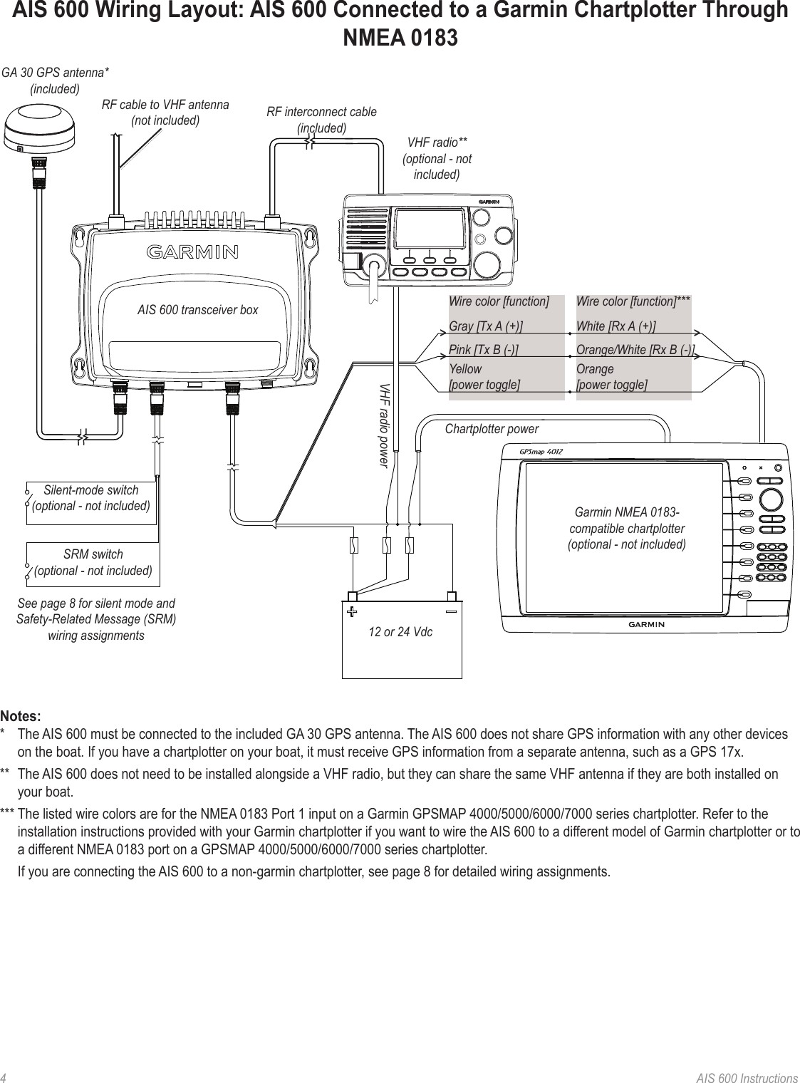
Next are wiring diagram examples showing the gpsmap using the. On arduino uno dm542t wiring diagram. Connect the bare wires to a panel mount to transfer data such as a flight plans to your aera. The black wire connects to the negative battery terminal or ground. Cummins isx fuel system diagram;
 Source: diyashtray.blogspot.com
System architecture figure illustrates an example block diagram of a g3x installation. Next are wiring diagram examples showing the gpsmap using the. This aera 796 cradle is wired with a 12/24v dc cigarette lighter plug. Gpsmap 3206/3210 owner’s manual i introduction > about this manual and manual conventions introduction thank you for choosing the garmin® gpsmap® 3206/3210. Garmin radome installation instructions 1 introduction thank you for choosing a garmin radome.
 Source: dentistmitcham.com
Optional garmin marine network components use specialized garmin network cables. For some installations, it may be necessary to drill 1.25” (31.7mm) holes to route the connector end of the cables. Garmin hereby grants permission to download a single copy of this manual onto. Gpsmap 3206/3210 owner’s manual introduction > installing your gpsmap 3206/3210, about this manual, and manual conventions introduction thank you for choosing the garmin ® gpsmap 3206/3210. To flush mount the gpsmap /c/c/ 1.
 Source: justanswer.com
Warn 9 5 ti wiring diagram. Garmin radome installation instructions 1 introduction thank you for choosing a garmin radome. The gpsmap 3005/3205 chartplotters do not have video input or output capabilities, so no cable is provided with those units. To flush mount the gpsmap /c/c/ 1. Gpsmap 3206/3210 owner’s manual introduction > installing your gpsmap 3206/3210, about this manual, and manual conventions introduction thank you for choosing the garmin ® gpsmap 3206/3210.
 Source: diyashtray.blogspot.com
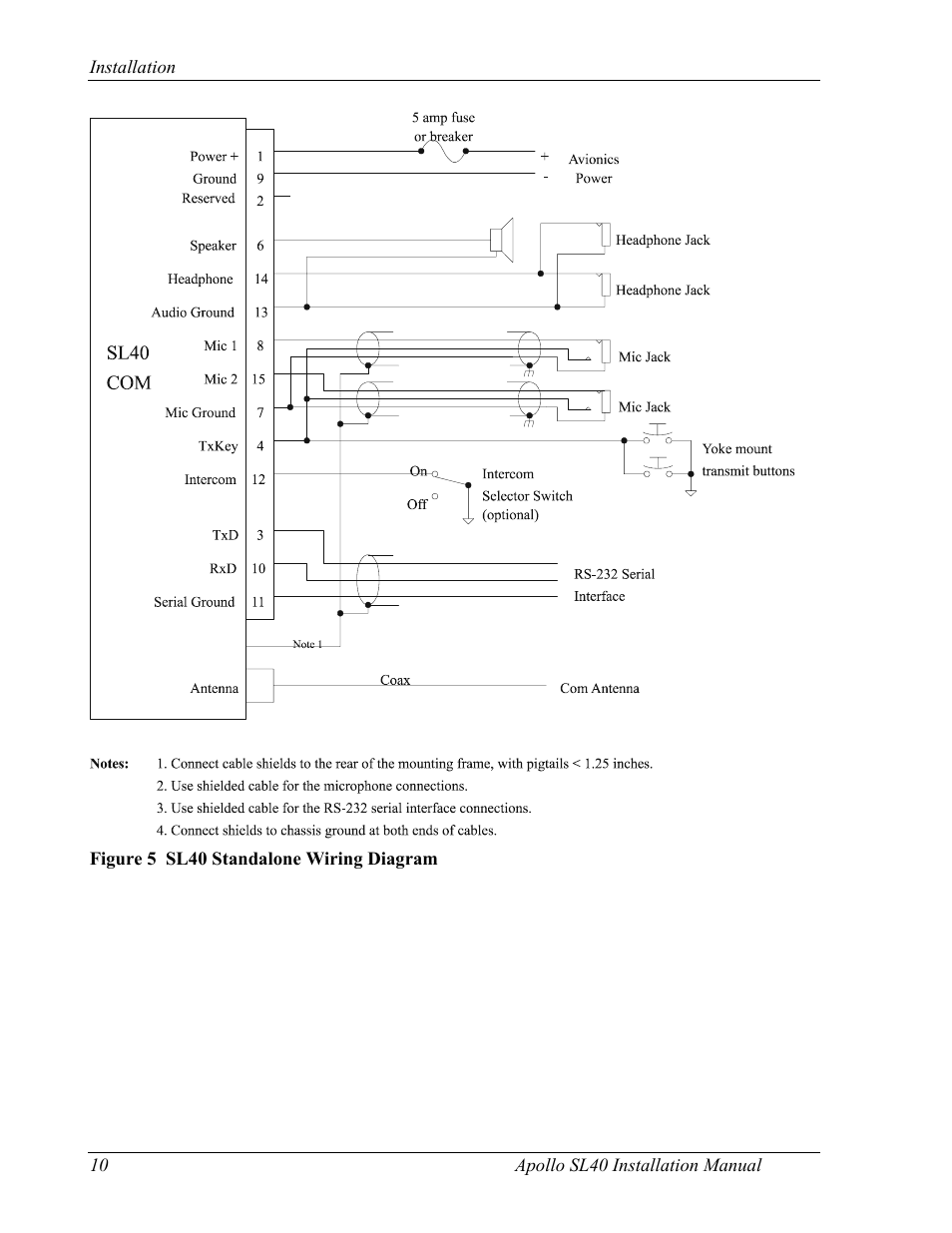
1993 sea nymph fm 160 wiring. (gtx 320 shown) £ garmin international, inc. This aera 796 cradle is wired with a 12/24v dc cigarette lighter plug. Wire gauge table figure 1 141.5 mm ship�s bow (5.57 ) 9.5 mm (7/16 ) 233 mm (9.17) distance gauge 2 meters (6 1/ 2 ft) 16 awg 4 meters (13 ft) 14. Connect the bare wires to a panel mount to transfer data such as a flight plans to your aera.
 Source: wiringdiagram.2bitboer.com
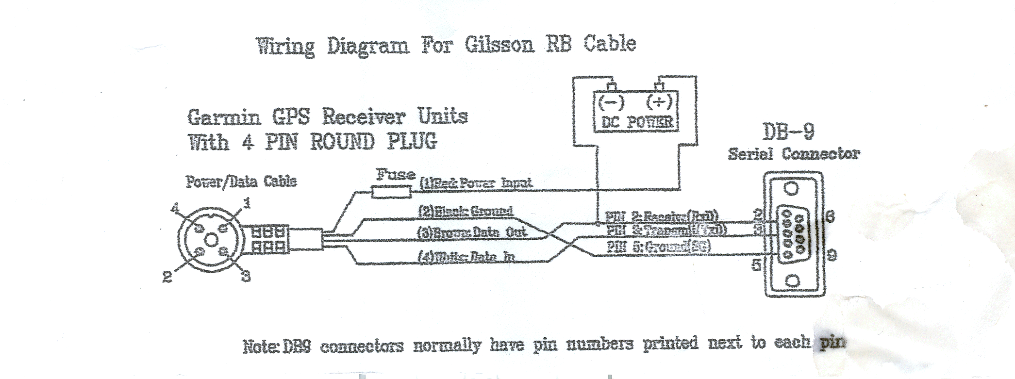
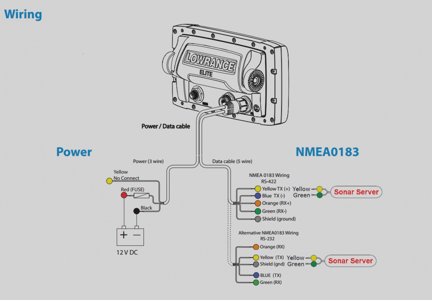
Wire color gps 17n/17hvs antenna black (ground) Arduino uno 24v dc power supply. The additional 2 wires are used to communicate with other devices so all you have to do is. Power/data cable wiring use the following diagram to connect the gps 17n/17hvs antenna to a gpsmap 3000 series chartplotter. Warn 9 5 ti wiring diagram.
![[DIAGRAM] Garmin Gps Wiring Diagram 2006 [DIAGRAM] Garmin Gps Wiring Diagram 2006](https://i.pinimg.com/originals/13/52/88/135288d23666b2ee48e8443ff6c28ff7.jpg) Source: powerdiagram.blogspot.com
Source: powerdiagram.blogspot.com
Warn 9 5 ti wiring diagram. Power/data cable wiring use the following diagram to connect the gps 17n/17hvs antenna to a gpsmap 3000 series chartplotter. If the serial connector already has wires attached, use appropriate wire connectors for the assembly as opposed to soldering the connections. The black wire connects to the negative battery terminal or ground. Garmin support center is where you will find answers to frequently asked questions and resources to help with all of your garmin products.
 Source: diyashtray.blogspot.com
Power/data cable wiring use the following diagram to connect the gps 17n/17hvs antenna to a gpsmap 3000 series chartplotter. Connect the bare wires to a panel mount to transfer data such as a flight plans to your aera. 2005 nissan frontier serpentine belt diagram. The following pages contain several wiring diagrams. 1993 sea nymph fm 160 wiring.
 Source: wiringmanualpdf.blogspot.com
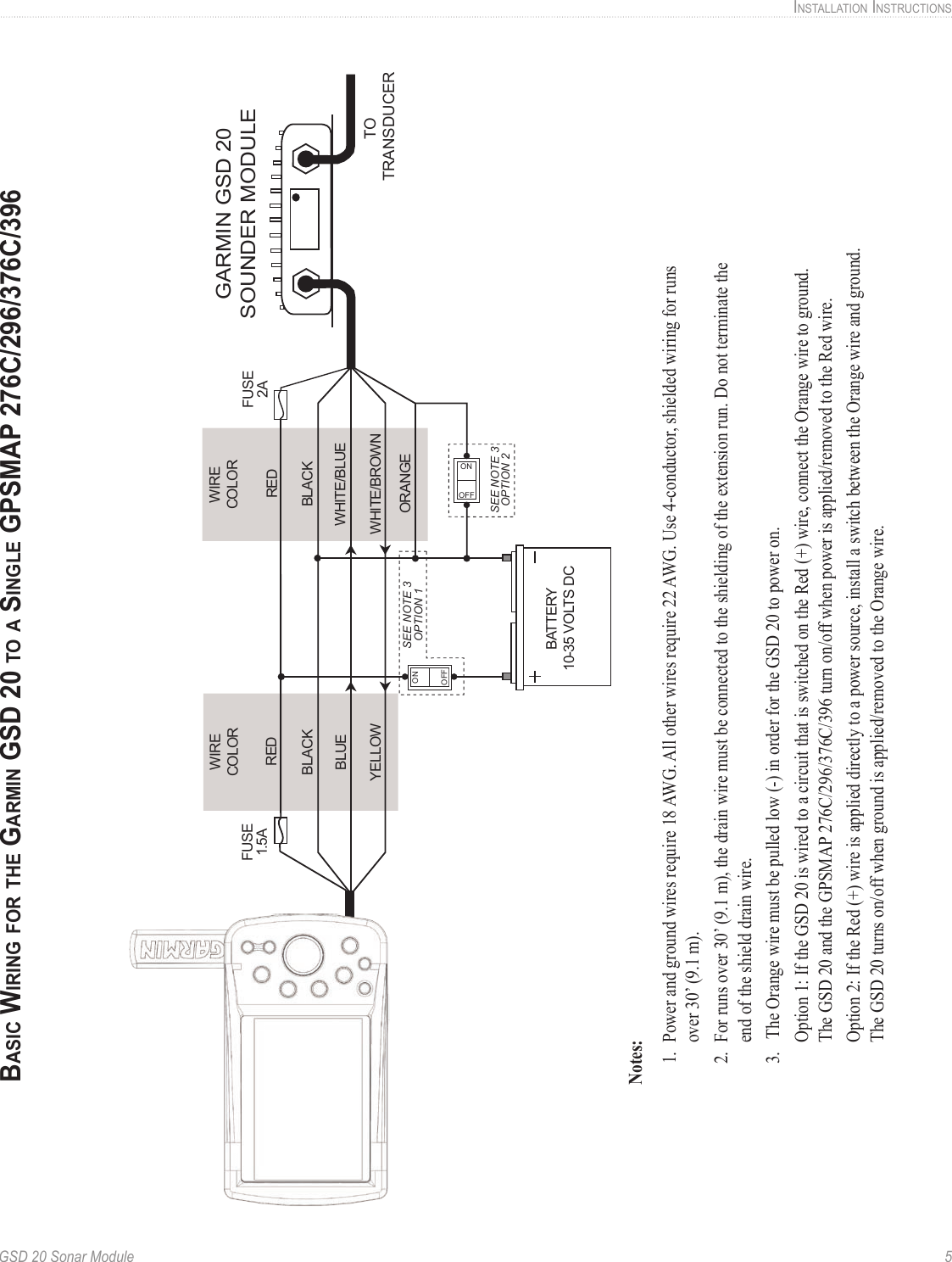
Manuals for gpsmap installation instructions, a, sep , 02, download. Garmin proprietary sonar module and nmea 0183 version 3.01. Casa vieja cieling fan style 22479 wiring diagram; 2005 nissan frontier serpentine belt diagram. For some installations, it may be necessary to drill 1.25” (31.7mm) holes to route the connector end of the cables.
 Source: thehulltruth.com
Temporarily attach mounting rails to the panel dock these instructions assume that you are installing the aera 796 panel dock in a standard radio stack, but that is not the only way to install it. For some installations, it may be necessary to drill 1.25” (31.7mm) holes to route the connector end of the cables. If the serial connector already has wires attached, use appropriate wire connectors for the assembly as opposed to soldering the connections. The gpsmap 3006/3206/3010/3210 chartplotters have video input and output capabilities, and a video cable is provided with those units. (gtx 320 shown) £ garmin international, inc.
 Source: manualzz.com
Wiring should be stripped to appropriate lengths to ensure proper fit into the connector. The following pages contain several wiring diagrams. Power/data cable wiring use the following diagram to connect the gps 17n/17hvs antenna to a gpsmap 3000 series chartplotter. Garmin radome installation instructions 1 introduction thank you for choosing a garmin radome. Solder all connections and seal the connection with heat shrink tubing.
This site is an open community for users to share their favorite wallpapers on the internet, all images or pictures in this website are for personal wallpaper use only, it is stricly prohibited to use this wallpaper for commercial purposes, if you are the author and find this image is shared without your permission, please kindly raise a DMCA report to Us.
If you find this site beneficial, please support us by sharing this posts to your favorite social media accounts like Facebook, Instagram and so on or you can also save this blog page with the title garmin 3206 wiring diagram by using Ctrl + D for devices a laptop with a Windows operating system or Command + D for laptops with an Apple operating system. If you use a smartphone, you can also use the drawer menu of the browser you are using. Whether it’s a Windows, Mac, iOS or Android operating system, you will still be able to bookmark this website.
Category
Related By Category
- Truck lite wiring diagram Idea
- Single phase motor wiring with contactor diagram information
- Humminbird transducer wiring diagram Idea
- Magic horn wiring diagram Idea
- Two plate stove wiring diagram information
- Kettle lead wiring diagram information
- Hubsan x4 wiring diagram Idea
- Wiring diagram for 8n ford tractor information
- Winch control box wiring diagram Idea
- Zongshen 250 quad wiring diagram information