Fuel tank pressure sensor wiring diagram information
Home » Trend » Fuel tank pressure sensor wiring diagram information
Your Fuel tank pressure sensor wiring diagram images are ready. Fuel tank pressure sensor wiring diagram are a topic that is being searched for and liked by netizens today. You can Download the Fuel tank pressure sensor wiring diagram files here. Download all free photos.
If you’re searching for fuel tank pressure sensor wiring diagram pictures information related to the fuel tank pressure sensor wiring diagram keyword, you have pay a visit to the ideal site. Our site frequently provides you with hints for downloading the highest quality video and image content, please kindly hunt and locate more enlightening video articles and images that match your interests.
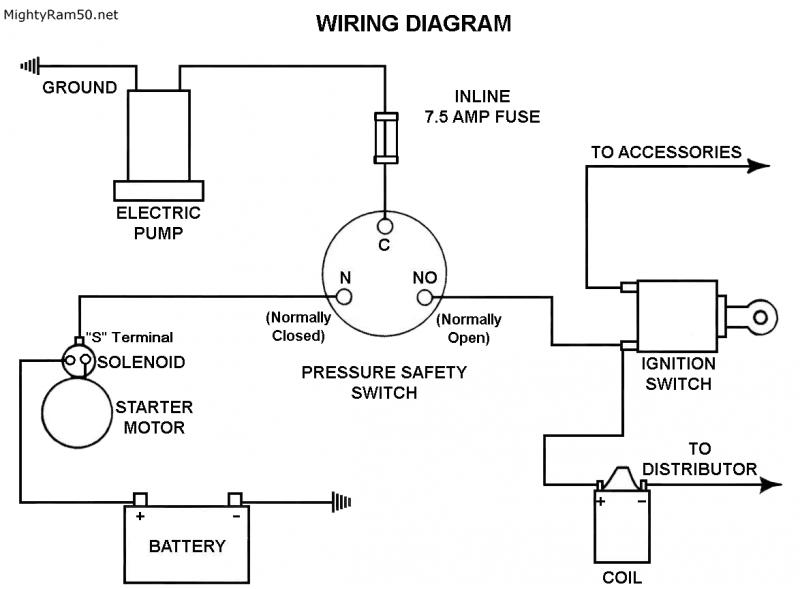
Fuel Tank Pressure Sensor Wiring Diagram. Coil needle 100 fuel pressure regulator the system pressure regulator maintains a constant fuel pressure to all injectors by regulating the quantity of fuel returned to the fuel tank. The regulator is connected to the intake manifold. 4) refill the fuel tank. 6) install the fuel filler cap.
 I have a 2000 Blazer and just went for an emission test From justanswer.com
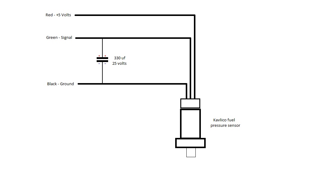
A fuel pressure sensor is a powered sensor that typically has three wires; It�s a 2002 and the code was 0453.i ask them at the dealer if they were sure that it wasn�t a bad wire or anything else and they said it was for sure the sensor. It’s a 3 wire sensor. The fuel tank pressure (ftp) sensor is an important part of the evaporative emissions control system that is designed to capture unburnt fuel vapors and reintroduce them back into the fuel system. In my case this is a problem because i�m using the sti harness. The fuel tank pressure sensor is located on the filler neck.
4) refill the fuel tank.
Cooing fan or ac not working checked 30 amp fuse an 10 amp. Hc doser fuel supply pressure control valve (km59 gen1 only) 29. If you find a circuit diagram for your fuel pressure sensor, you can measure the resistance at the pins to see if there is a short circuit or open circuit in the sensor. P0453 may set anytime pcm detects high voltage in fuel tank pressure circuit. Refer to fuel tank replacement. It reveals the components of the circuit as simplified shapes as well as the power and also signal links in between the tools.
 Source: gm-trucks.com
A fuel pressure sensor is a powered sensor that typically has three wires; The fuel tank pressure (ftp) sensor is an important part of the evaporative emissions control system that is designed to capture unburnt fuel vapors and reintroduce them back into the fuel system. So my 2001 is throwing a p0453 code and i�m pretty sure it�s a faulty fuel tank pressure sensor. Hc doser fuel supply pressure control valve (km59 gen1 only) 29. Worse case your issue is.
 Source: spridgetguru.com
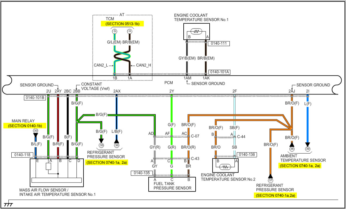
- connect the negative battery cable. I�m looking at the wiring diagram for the 02 wrx and 05 sti and there are missing parts. The fuel tank pressure sensor is responsible for detecting leaks in the fuel system, whether it be an evaporative leak or bad seal on the fuel cap. Ftp sensor open or shorted to vref, sig rtn shorted to vpwr, damaged ftp sensor or faulty pcm. Worse though (at least for me) is that the pinouts for the wide white connector under the rear seat that goes to the fuel tank is different.
Source: skippingtheinbetween.blogspot.com
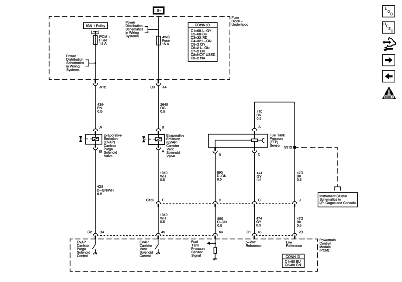
The 5 volt reference is only for the sensor it is on pin 46 on the pcm a grey wire with black stripe. That leaves the 5 volt and signal return. The 5 volt reference is only for the sensor it is on pin 46 on the pcm a grey wire with black stripe. The wiring is for the fuel tank pressure sensor is found here: The regulator is connected to the intake manifold.
 Source: studebaker-info.org
The wiring is for the fuel tank pressure sensor is found here: This wiring harness print does not include the attachment locations for the roush cleantech tank jumper harness to the rear chassis harness.) 100257a can harness fuel tank jumper harness ford harness connector trailer brake module connector (if. Fuel tank to intake manifold electro. If mounting the pump in the tank is not an option, install the pump as close as possible to the tank. P0453 may set anytime pcm detects high voltage in fuel tank pressure circuit.
 Source: mx5manual.com
This sensor is generally mounted in the engines fuel rail or fuel pressure regulator, and measures the fuel pressure acting on the fuel injectors. Hc doser fuel supply pressure control valve (km59 gen1 only) 29. I�m looking at the wiring diagram for the 02 wrx and 05 sti and there are missing parts. 1) install the fuel tank pressure sensor (1) on the fuel sender assembly (2). I�d also like the wiring diagram showing the connections to the fpdm.
 Source: f150forum.com
Kickdown switch arrow is integrated into accelerator cable and is located on. If the fuel gauges both work the sensor ground is likely good. The 5 volt reference is only for the sensor it is on pin 46 on the pcm a grey wire with black stripe. 3) install the fuel tank. Hc doser fuel supply pressure control valve (km59 gen1 only) 29.
 Source: justanswer.com
Pcm monitors ftp input signal to pcm. In order to optimize engine combustion, its maximum injection pressure is up 5. P0183 fuel temperature sensor (a) circuit high p0190 fuel pressure sensor a circuit p0192 fuel pressure sensor a circuit low p0193 fuel pressure sensor a circuit high p025a fuel pump control module circuit range/performance a p027a fuel pump control module circuit range/performance b p03xx misfire p0460 fuel level sender a circuit This sensor is generally mounted in the engines fuel rail or fuel pressure regulator, and measures the fuel pressure acting on the fuel injectors. This sensor is an integral part of your car’s evaporative emissions system, also known as evap.
 Source: 2carpros.com
This is the fuel tank pressure sensor, the is located on the top of the fuel tank, this may be caused by a bad sensor orbad wiring, you will need to drop the fuel tank and check the connection to sensor and then follow wiring back and check for bad wiring to sensor, the wiring is a problem on some of these. Worse case your issue is. A 5v+ power wire, a signal wire to the ecu, and a signal ground. The pcm uses the frp signal to command the correct injector timing and pulse width for correct fuel delivery at all speed and load conditions. 6) install the fuel filler cap.
 Source: autozone.com
Normal voltage from this sensor with no vacuum or pressure on the system should be 2.37 to 2.97v. Ran the vin through gm and it shows only a single sensor. The code if we are talking about the. Wiring diagram ecu 2kd ftv throttle systems engineering systems engineering ecu crankshaft position sensor. Worse case your issue is.
 Source: justanswer.com
A 5v+ power wire, a signal wire to the ecu, and a signal ground. 5) connect the negative battery cable. This wiring harness print does not include the attachment locations for the roush cleantech tank jumper harness to the rear chassis harness.) 100257a can harness fuel tank jumper harness ford harness connector trailer brake module connector (if. This sensor is generally mounted in the engines fuel rail or fuel pressure regulator, and measures the fuel pressure acting on the fuel injectors. Pressure sensor wiring diagram written by nan 28 monday, may 17, 2021 add comment edit.
 Source: hemanual.org
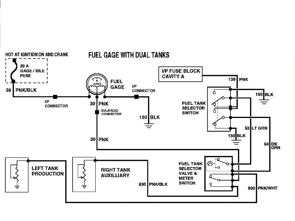
Worse though (at least for me) is that the pinouts for the wide white connector under the rear seat that goes to the fuel tank is different. Ftp circuit open vref shorted to vpwr damaged pcm 1) install the fuel tank pressure sensor (1) on the fuel sender assembly (2). The sensor ground is shared with the fuel level sensors in both tanks. It’s a 3 wire sensor.
 Source: justanswer.com
The fuel tank pressure (ftp) sensor is an important part of the evaporative emissions control system that is designed to capture unburnt fuel vapors and reintroduce them back into the fuel system. Fuel return to tank 32. In order to optimize engine combustion, its maximum injection pressure is up 5. It reveals the components of the circuit as simplified shapes as well as the power and also signal links in between the tools. P0453 may set anytime pcm detects high voltage in fuel tank pressure circuit.
 Source: wiring121.blogspot.com
Cooing fan or ac not working checked 30 amp fuse an 10 amp acfuse both good changed out fan relay and ac relay and high/low pressure switch and changed out temp sensor. Cooing fan or ac not working checked 30 amp fuse an 10 amp acfuse both good changed out fan relay and ac relay and high/low pressure switch and changed out temp sensor. Fuel tank to intake manifold electro. It�s a 2002 and the code was 0453.i ask them at the dealer if they were sure that it wasn�t a bad wire or anything else and they said it was for sure the sensor. 2) connect the fuel tank pressure sensor electrical connector.
 Source: 73.bloxhuette.de
Code sets when signal average jumps above a minimum allowable parameter. The 5 volt reference is only for the sensor it is on pin 46 on the pcm a grey wire with black stripe. Hc doser fuel supply pressure control valve (km59 gen1 only) 29. Pcm sends a reference voltage of 5v to the sensor and tells if there is pressure or vacuum in the fuel tank by the voltage that returns from the sensor. 3) install the fuel tank.
 Source: diagramweb.net
If you find a circuit diagram for your fuel pressure sensor, you can measure the resistance at the pins to see if there is a short circuit or open circuit in the sensor. Coil needle 100 fuel pressure regulator the system pressure regulator maintains a constant fuel pressure to all injectors by regulating the quantity of fuel returned to the fuel tank. Cooing fan or ac not working checked 30 amp fuse an 10 amp. So my 2001 is throwing a p0453 code and i�m pretty sure it�s a faulty fuel tank pressure sensor. Cooing fan or ac not working checked 30 amp fuse an 10 amp acfuse both good changed out fan relay and ac relay and high/low pressure switch and changed out temp sensor.
 Source: schematron.org
If you find a circuit diagram for your fuel pressure sensor, you can measure the resistance at the pins to see if there is a short circuit or open circuit in the sensor. Before i go dropping the tank can anyone tell me if the fuel tank pressure sensor is located on top of (outside) the gas tank or inside the tank as part of the fuel pump assembly? It’s a 3 wire sensor. 3) install the fuel tank. You should have 5v on the sensor feed and return circuits and ground on the third circuit.
 Source: justanswer.com
Code sets when signal average jumps above a minimum allowable parameter. Coil needle 100 fuel pressure regulator the system pressure regulator maintains a constant fuel pressure to all injectors by regulating the quantity of fuel returned to the fuel tank. The fuel tank pressure sensor is located on the filler neck. Kickdown switch arrow is integrated into accelerator cable and is located on. Fuel tank to intake manifold electro.
 Source: annawiringdiagram.com
- install the fuel filler cap. Pcm monitors ftp input signal to pcm. Discussion starter · #1 · mar 4, 2012. 1) install the fuel tank pressure sensor (1) on the fuel sender assembly (2). Fuel return to tank 32.
This site is an open community for users to do submittion their favorite wallpapers on the internet, all images or pictures in this website are for personal wallpaper use only, it is stricly prohibited to use this wallpaper for commercial purposes, if you are the author and find this image is shared without your permission, please kindly raise a DMCA report to Us.
If you find this site adventageous, please support us by sharing this posts to your preference social media accounts like Facebook, Instagram and so on or you can also bookmark this blog page with the title fuel tank pressure sensor wiring diagram by using Ctrl + D for devices a laptop with a Windows operating system or Command + D for laptops with an Apple operating system. If you use a smartphone, you can also use the drawer menu of the browser you are using. Whether it’s a Windows, Mac, iOS or Android operating system, you will still be able to bookmark this website.
Category
Related By Category
- Predator 670 engine wiring diagram Idea
- Frsky x8r wiring diagram information
- Pioneer ts wx130da wiring diagram Idea
- Johnson 50 hp wiring diagram Idea
- Kohler voltage regulator wiring diagram Idea
- Johnson 50 hp outboard wiring diagram information
- Kti hydraulic remote wiring diagram Idea
- Pyle plpw12d wiring diagram information
- Tx9600ts wiring diagram information
- Lifan 50cc wiring diagram information