Fuel sender fuel gauge wiring diagram Idea
Home » Trending » Fuel sender fuel gauge wiring diagram Idea
Your Fuel sender fuel gauge wiring diagram images are ready in this website. Fuel sender fuel gauge wiring diagram are a topic that is being searched for and liked by netizens now. You can Find and Download the Fuel sender fuel gauge wiring diagram files here. Get all free vectors.
If you’re searching for fuel sender fuel gauge wiring diagram pictures information connected with to the fuel sender fuel gauge wiring diagram keyword, you have come to the right blog. Our site frequently provides you with hints for refferencing the highest quality video and picture content, please kindly hunt and locate more informative video content and graphics that match your interests.
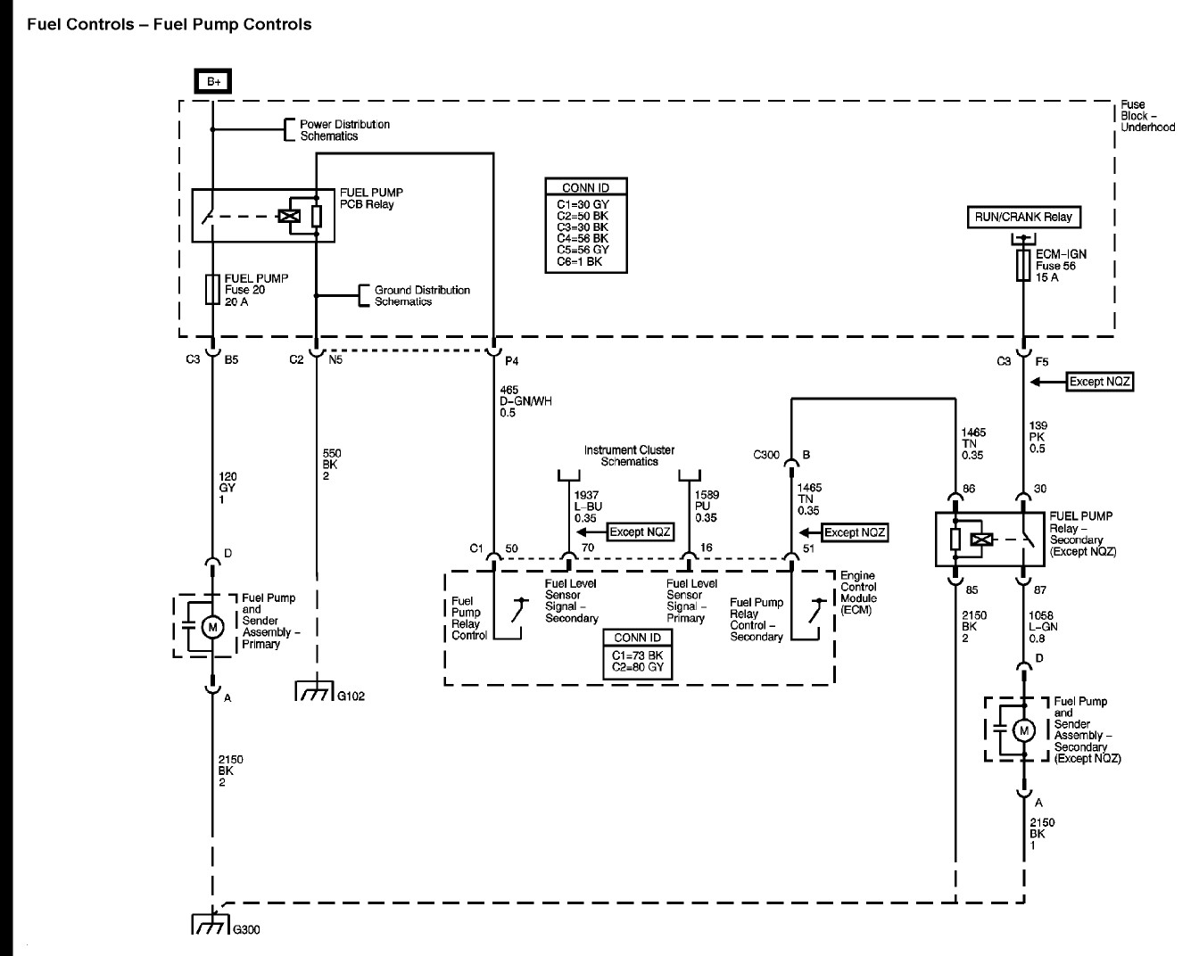
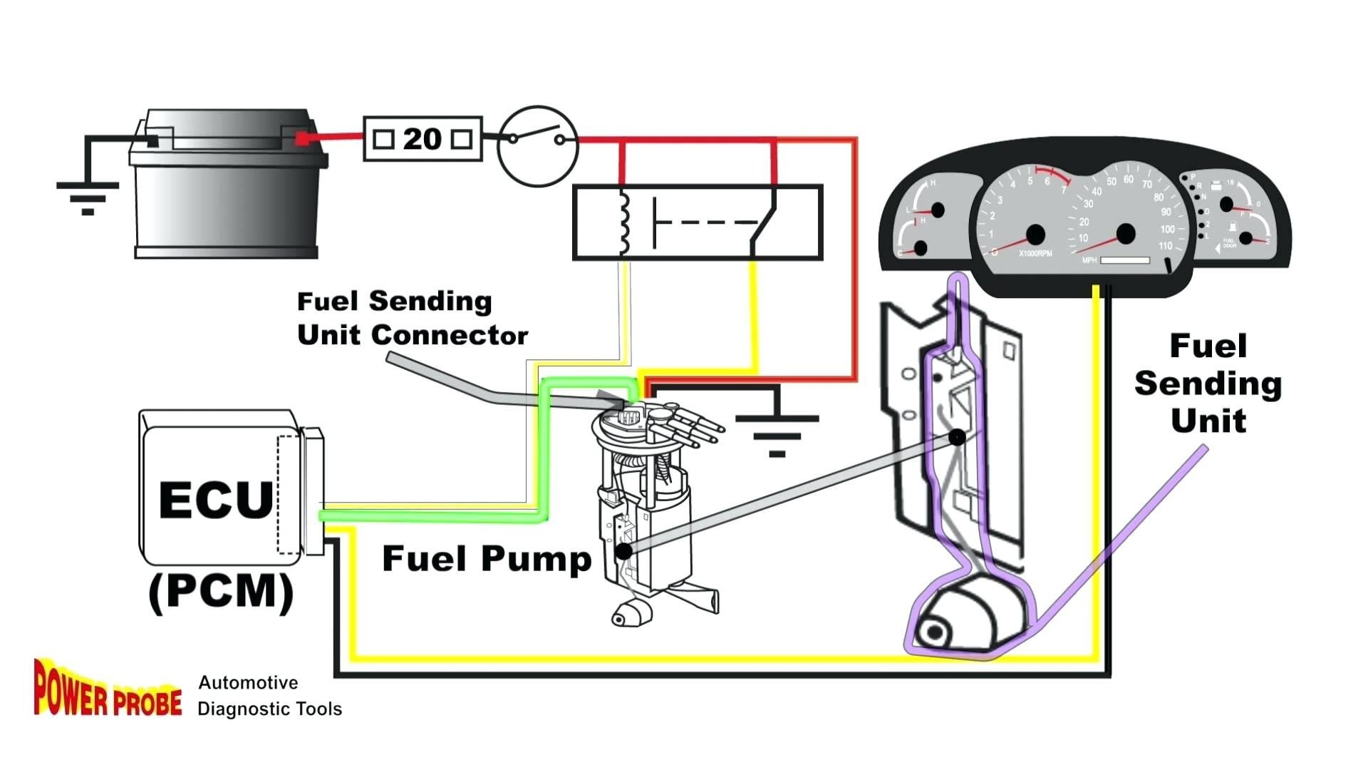
Fuel Sender Fuel Gauge Wiring Diagram. Wiring diagram of fuel gauge for toyota corolla 2006. Remove and replace sending unit. After wiring gauge/sender, calibrate them (diagram e). Pin on velvet 1 for fuel pressure gauge install the 1 8 npt pressure sender into the fuel system see caution below.
 Wiring For Gas Gauge 24h schemes From julia-woehlert.de
To confirm gage operation reverse wiring to the guage and it will reverse the guage, confirming tha the gauge.is ok. But, it doesn’t mean connection between the cables. So apparently the fuel gauge is registering a low fuel level, but you just can�t see it. When you make use of your finger or perhaps the actual circuit with your eyes, it is easy to mistrace the circuit. 800 x 600 px source. Boat fuel gauge wiring diagram.
Power up the gauge by connecting the power wire to the ignition (marked “i”) stud and if you obtain a reading then there is a short in the wiring or the sender.
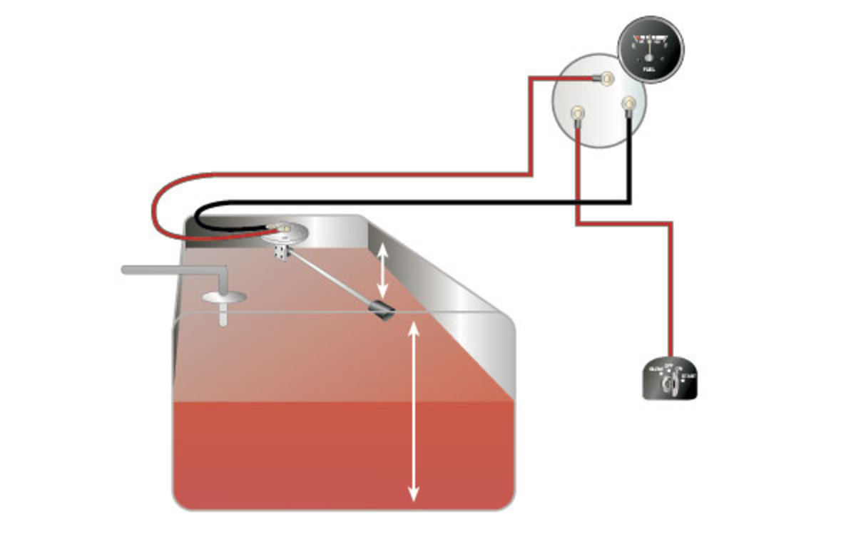
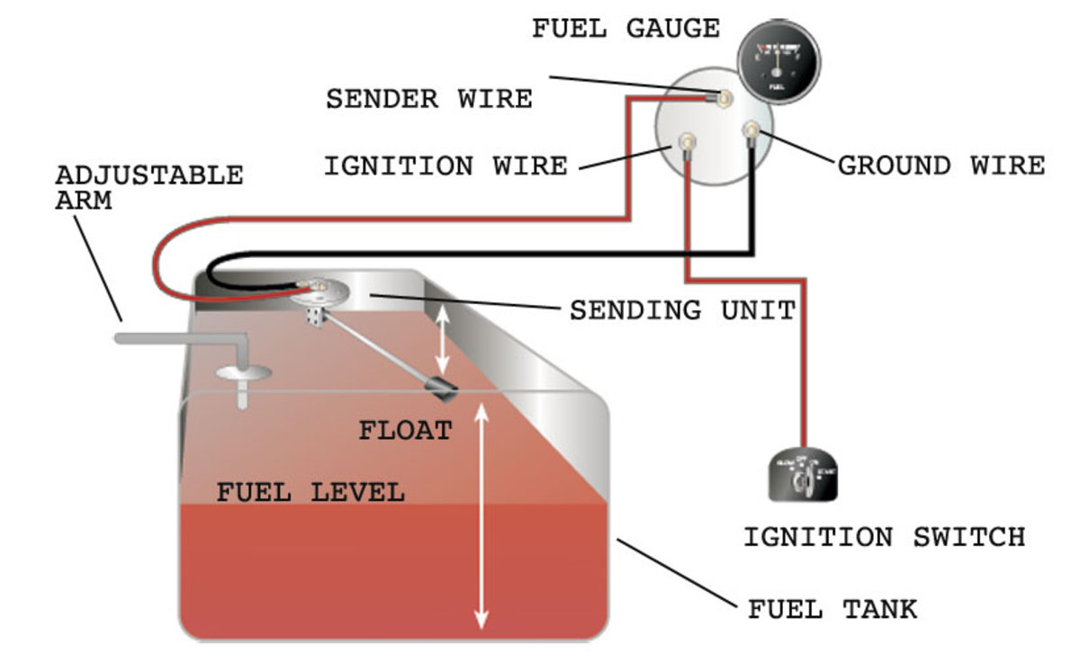
Boat fuel gauge wiring diagram. “s” for the sender, “g” or “—” for the ground, and “i” for the ignition. Check the wiring diagram that comes with the kit and mark the back of the new fuel gauge with symbols for each post. Fuel gauge sending unit wiring diagram wiring diagram is a simplified customary pictorial representation of an electrical circuit. March 8, 2021 · wiring diagram. How to install a moeller fuel gauge.
 Source: annawiringdiagram.com
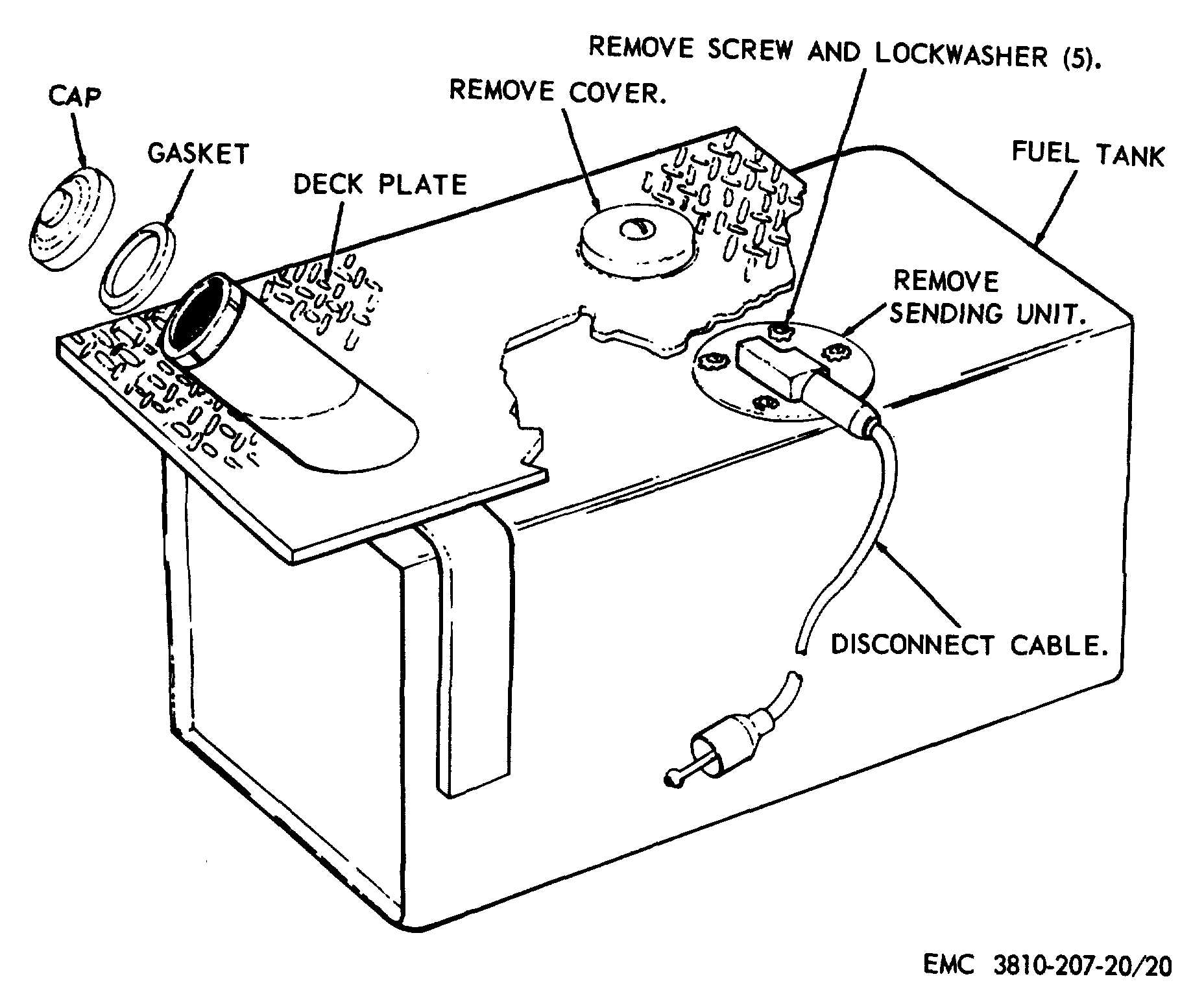
The sending unit will ground through the mount screws. Turn ignition on and see needle move to full side (it�ll take some time). Fuel systems marine voltage i to g terminal 10 to 16 volts. Remove the sender from the tank. Check the wiring diagram that comes with the kit and mark the back of the new fuel gauge with symbols for each post.
 Source: kovodym.blogspot.com
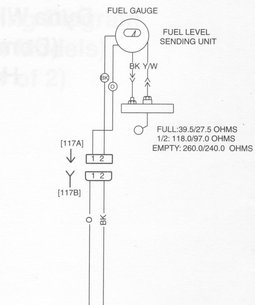
2004 fleetwood revolution battery wiring diagram online wiring diagram gauge and sending unit wiring diagram and industry […] Gauge pointer should be at the position shown in the lower portion of the diagram. With this sort of an illustrative guide, you will have the. Always disconnect battery ground before making any electrical connections. To test senders, the resistance values are shown at minimum and full gauge scales.
 Source: wholefoodsonabudget.com
To test senders, the resistance values are shown at minimum and full gauge scales. Run wires from the adjustable fuel gauge. Turn ignition on and see needle move to full side (it�ll take some time). First some good practices one is proper wiring fusing and using the right safety circuits to. 1 trick that we 2 to printing a similar wiring plan off twice.
 Source: ricardolevinsmorales.com
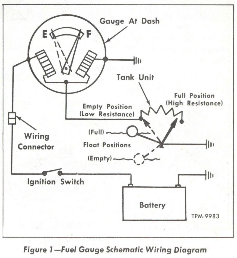
Wema fuel sender wiring diagram by vallery masson on may 4, 2021 measure the depth of your fuel tank. When you make use of your finger or perhaps the actual circuit with your eyes, it is easy to mistrace the circuit. 800 x 600 px source. The fuel gage circuit consists of the sending unit in the fuel tank, the gauge in the dash, and a 12 volt battery) here is a picture of a sending unit on a bronco ii wiring diagram: If the fuel gauges sending unit wire see�s 0 ohms then the gauge should read empty.
 Source: wiringall.com
When you make use of your finger or perhaps the actual circuit with your eyes, it is easy to mistrace the circuit. How to install a moeller fuel gauge. So apparently the fuel gauge is registering a low fuel level, but you just can�t see it. Wiring diagram autometer electric fuel pressure gauge wiring diagram on march 3, 2022 if a new hole is drilled in the firewall a grommet is recommended. March 8, 2021 · wiring diagram.
 Source: 2020cadillac.com
As stated earlier, the traces at a universal fuel gauge wiring diagram signifies wires. Installing a universal fuel sender from veethree elec marine llce nz and a mercury digital fuel gauge from trademe seller silverdalemarine on my boat. Wiring diagram autometer electric fuel pressure gauge wiring diagram on march 3, 2022 if a new hole is drilled in the firewall a grommet is recommended. Find great deals on ebay for faria marine fuel gauge. When you make use of your finger or perhaps the actual circuit with your eyes, it is easy to mistrace the circuit.
 Source: annawiringdiagram.com
To confirm gage operation reverse wiring to the guage and it will reverse the guage, confirming tha the gauge.is ok. Fuel gauge diagram all in one digital display system the digidash 2 lite is for road and track day use the dd2 lite is a stand alone system supplied with its own set of sensors including coolant temperature oil temperature oil pressure fuel level and speed, wema The fuel gage circuit consists of the sending unit in the fuel tank, the gauge in the dash, and a 12 volt battery) here is a picture of a sending unit on a bronco ii wiring diagram: With this sort of an illustrative guide, you are going to be able to troubleshoot, prevent, and complete your tasks without difficulty. Sender gauge resistance (i guess they mean.
 Source: 2020cadillac.com
With the tank empty, use the calibration screw to move the pointer to “e.” when the pointer rests on “e” with the tank empty, the gauge and sender are calibrated and ready for use, and the gauge can be wiring the fuel gauge: Print the wiring diagram off plus use highlighters to trace the signal. March 8, 2021 · wiring diagram. Refer to the vdo catalog for matching fuel gauges. The unit can be adjusted to read accurately in tanks from 6 to 23 deep.
![[DIAGRAM] Autometer Fuel Gauge Wiring Diagram FULL Version [DIAGRAM] Autometer Fuel Gauge Wiring Diagram FULL Version](https://www.soundingsonline.com/.image/t_share/MTQ5Nzk4MTg3ODcwMjAxMjQ1/gauge-fuel-62618.jpg) Source: kingsage.cheminsdetablemagazine.fr
Source: kingsage.cheminsdetablemagazine.fr
Testing a faria gauge with american resistance sender 1.) to test the discrete gauge without a faria tester; Find great deals on ebay for faria marine fuel gauge. Fuel gauge sending unit wiring diagram. Gauge pointer should be at the position shown in the lower portion of the diagram. The fuel gage circuit consists of the sending unit in the fuel tank, the gauge in the dash, and a 12 volt battery) here is a picture of a sending unit on a bronco ii wiring diagram:
 Source: sailmagazine.com
Turn ignition on and see needle move to full side (it�ll take some time). If the gauge then reads full scale then the problem was with your sender. Wema fuel sender wiring diagram by vallery masson on may 4, 2021 measure the depth of your fuel tank. The sending unit will ground through the mount screws. Sometimes, the wires will cross.
 Source: ricardolevinsmorales.com
Boat fuel gauge wiring diagram. “s” for the sender, “g” or “—” for the ground, and “i” for the ignition. With this sort of an illustrative guide, you are going to be able to troubleshoot, prevent, and complete your tasks without difficulty. The unit can be adjusted to read accurately in tanks from 6 to 23 deep. Parts of the fuel level sender unit to be ad fuel level sender installation:
 Source: annawiringdiagram.com
Installing a universal fuel sender from veethree elec marine llce nz and a mercury digital fuel gauge from trademe seller silverdalemarine on my boat. The unit can be adjusted to read accurately in tanks from 6 to 23 deep. Refer to the vdo catalog for matching fuel gauges. October 7, 2020 · wiring diagram. The fuel gauge reads the resistance to ground check the wires on the back of the gauge pink to s terminal and black to g terminal.
 Source: ricardolevinsmorales.com
When you make use of your finger or perhaps the actual circuit with your eyes, it is easy to mistrace the circuit. Fuel gauge sending unit wiring diagram. Boat fuel tank gauge wiring diagram wiring diagram is a simplified standard pictorial representation of an electrical circuit. Connect terminals 2 & 3 on the wire harness side connector through a 3.4 w light bulb. It is , unfortunately, located inside of the fuel tank.
 Source: wiringall.com
The unit can be adjusted to read accurately in tanks from 6 to 23 deep. The unit can be adjusted to read accurately in tanks from 6 to 23 deep. Boat fuel tank gauge wiring diagram wiring diagram is a simplified standard pictorial representation of an electrical circuit. Print the wiring diagram off plus use highlighters to trace the signal. 1 trick that we 2 to printing a similar wiring plan off twice.
 Source: ricardolevinsmorales.com
With this sort of an illustrative manual, you are going to have the ability to troubleshoot, stop, and complete your assignments with ease. “s” for the sender, “g” or “—” for the ground, and “i” for the ignition. 800 x 600 px source. It is the sending unit, usually the veryable resister and arm. Yamaha fuel management wiring the hull truth boating and fishing forum gauges sender diagram for 6y5 gauge outboard parts analog conversion pro series fm manualzz how to test replace your sending unit sail magazine quick tach question with pics multi ribnet forums round gps sd ii white face 6y7 85750 30 00 partsvu faria including digital discussion sort of an.
 Source: diagramweb.net
Sender gauge resistance (i guess they mean. Fuel gauge sending unit wiring diagram wiring diagram is a simplified customary pictorial representation of an electrical circuit. Check the wiring diagram that comes with the kit and mark the back of the new fuel gauge with symbols for each post: Fuel systems marine voltage i to g terminal 10 to 16 volts. April 25, 2021 · wiring diagram.
 Source: schematron.org
Equus (have fuel gauges for ford).one wire goes to the center pin on the tank sending unit, one goes to ground, and the third connects to a volt source, normally the ignition switch. First some good practices one is proper wiring fusing and using the right safety circuits to. Gauge mounts in a 25 8 hole for 2 5 8 gauges and a 2 1 16 hole for 2 1 16 gauges. Parts of the fuel level sender unit to be ad fuel level sender installation: As stated earlier, the traces at a universal fuel gauge wiring diagram signifies wires.
 Source: 2020cadillac.com
It is , unfortunately, located inside of the fuel tank. Fuel gauge sending unit wiring diagram. First some good practices one is proper wiring fusing and using the right safety circuits to. “s” for the sender, “g” or “—” for the ground, and “i” for the ignition. October 7, 2020 · wiring diagram.
This site is an open community for users to share their favorite wallpapers on the internet, all images or pictures in this website are for personal wallpaper use only, it is stricly prohibited to use this wallpaper for commercial purposes, if you are the author and find this image is shared without your permission, please kindly raise a DMCA report to Us.
If you find this site convienient, please support us by sharing this posts to your preference social media accounts like Facebook, Instagram and so on or you can also save this blog page with the title fuel sender fuel gauge wiring diagram by using Ctrl + D for devices a laptop with a Windows operating system or Command + D for laptops with an Apple operating system. If you use a smartphone, you can also use the drawer menu of the browser you are using. Whether it’s a Windows, Mac, iOS or Android operating system, you will still be able to bookmark this website.
Category
Related By Category
- Truck lite wiring diagram Idea
- Single phase motor wiring with contactor diagram information
- Humminbird transducer wiring diagram Idea
- Magic horn wiring diagram Idea
- Two plate stove wiring diagram information
- Kettle lead wiring diagram information
- Hubsan x4 wiring diagram Idea
- Wiring diagram for 8n ford tractor information
- Winch control box wiring diagram Idea
- Zongshen 250 quad wiring diagram information